Towing Tank Facility - nptel - Indian Institute of Technology Madras
Towing Tank Facility - nptel - Indian Institute of Technology Madras
Towing Tank Facility - nptel - Indian Institute of Technology Madras

You also want an ePaper? Increase the reach of your titles
YUMPU automatically turns print PDFs into web optimized ePapers that Google loves.
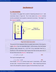
Hydraulics Pr<strong>of</strong>. B.S. Thandaveswara<br />
<strong>Towing</strong> <strong>Tank</strong> <strong>Facility</strong><br />
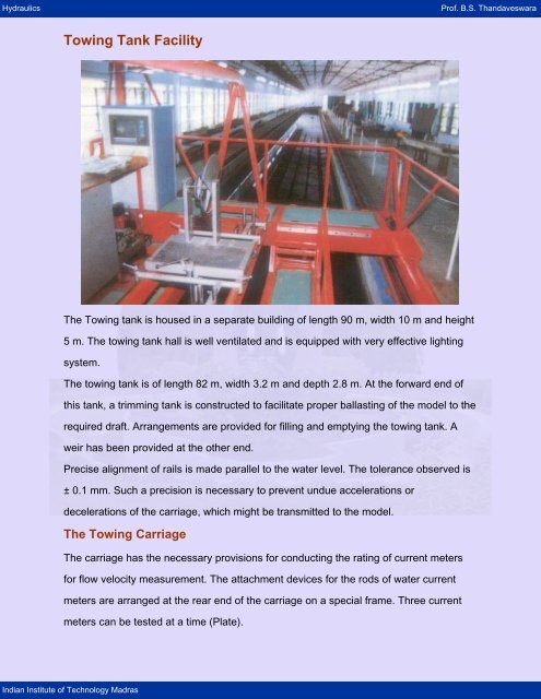
The <strong>Towing</strong> tank is housed in a separate building <strong>of</strong> length 90 m, width 10 m and height<br />
5 m. The towing tank hall is well ventilated and is equipped with very effective lighting<br />
system.<br />
The towing tank is <strong>of</strong> length 82 m, width 3.2 m and depth 2.8 m. At the forward end <strong>of</strong><br />
this tank, a trimming tank is constructed to facilitate proper ballasting <strong>of</strong> the model to the<br />
required draft. Arrangements are provided for filling and emptying the towing tank. A<br />
weir has been provided at the other end.<br />
Precise alignment <strong>of</strong> rails is made parallel to the water level. The tolerance observed is<br />
± 0.1 mm. Such a precision is necessary to prevent undue accelerations or<br />
decelerations <strong>of</strong> the carriage, which might be transmitted to the model.<br />
The <strong>Towing</strong> Carriage<br />
The carriage has the necessary provisions for conducting the rating <strong>of</strong> current meters<br />
for flow velocity measurement. The attachment devices for the rods <strong>of</strong> water current<br />
meters are arranged at the rear end <strong>of</strong> the carriage on a special frame. Three current<br />
meters can be tested at a time (Plate).<br />
<strong>Indian</strong> <strong>Institute</strong> <strong>of</strong> <strong>Technology</strong> <strong>Madras</strong>
Hydraulics Pr<strong>of</strong>. B.S. Thandaveswara<br />
The carriage has two speed ranges,<br />
(i) 0.02 m s -1 to 0.50 m s -1<br />
(ii) 0.50 m s -1 to 5.50 m s -1<br />
In the low speed range it can be operated by a low duty D.C. motor (manual control<br />
only), whereas in the higher speed range it can be operated by a heavy duty D.C. motor<br />
fed by a Ward-Leonard set, (both by manual and electronic control) and the A.C./D.C.<br />
power supplied via overhead bus bars. The approximate speed <strong>of</strong> the carriage is<br />
indicated on a speedometer fixed in the panel on the carriage.<br />
The towing carriage is provided with braking system for stopping at any position in the<br />
towing tank. Also for safety purposes, emergency braking rails are provided at both the<br />
ends <strong>of</strong> the towing tank, which retard the towing carriage at 10 m s -2 .<br />
For Testing <strong>of</strong> ship models in shallow water, the observation bridge and the measuring<br />
frame can be lowered in the centre <strong>of</strong> the towing carriage.<br />
Calibration <strong>of</strong> Flow Meters<br />
Flow meters such as pitot tubes, pilot cylinder, and current meters are rated before<br />
being put to use. For example, in the case <strong>of</strong> current meters, it is necessary to<br />
determine the constants which establish the relation between the number <strong>of</strong> revolutions<br />
<strong>Indian</strong> <strong>Institute</strong> <strong>of</strong> <strong>Technology</strong> <strong>Madras</strong>
Hydraulics Pr<strong>of</strong>. B.S. Thandaveswara<br />
per second <strong>of</strong> the propeller and the water flow velocity rating is carried out in still water<br />
<strong>of</strong> towing tank.<br />
Test Installation for Rating <strong>of</strong> Current Meter<br />
Measuring Equipment<br />
The carriage is equipped for the concurrent connection <strong>of</strong> three current meters to the<br />
sockets located on a small switch desk. The exact measurement <strong>of</strong> the speed <strong>of</strong> the<br />
carriage is made with the use <strong>of</strong> a measuring wheel. The distance measuring wheel<br />
provides for the three different distance sampling signals to suit different speed ranges.<br />
These signals are routed through a crystal controlled timing mechanism.<br />
The Data Acquisition System is mounted on the carriage for conducting the test. Also<br />
the digital timing mechanism which receives and indicates on four individual displays,<br />
the time intervals during each run <strong>of</strong> rating as follows:<br />
1. The time that elapses for the carriage to traverse a distance <strong>of</strong> 10 m at the set<br />
constant speed.<br />
2. The time that elapses for the completion <strong>of</strong> 10/20 revolutions <strong>of</strong> each current meter.<br />
Testing Procedure<br />
The procedure for Rating <strong>of</strong> Current meter as in accordance with HIS: 3910 -1966 and<br />
HIS: 3918- 1966<br />
Spin Test<br />
The current meter is made to rest on horizontal plane and a spin is induced to the<br />
bucket wheel by means <strong>of</strong> an air jet from a solenoid valve/nozzle. The air jet is<br />
controlled to be active for a duration till the equilibrium condition is reached, maintaining<br />
an air pressure <strong>of</strong> 4 kg cm -2 . At the end <strong>of</strong> the solenoid valve action, a digital timer is<br />
used for measuring the spinning time.<br />
Current Meter Installation<br />
Three current meters can be fixed to the special frame at the rear end <strong>of</strong> the carriage.<br />
Two current meters are fixed at a distance <strong>of</strong> 50 cm from the sides <strong>of</strong> the tank and the<br />
third one is fixed at the centre. The current meters are submerged to a depth <strong>of</strong> 50 cm.<br />
<strong>Indian</strong> <strong>Institute</strong> <strong>of</strong> <strong>Technology</strong> <strong>Madras</strong>
Hydraulics Pr<strong>of</strong>. B.S. Thandaveswara<br />
They are held by vertical rigid rods fixed with the axis <strong>of</strong> the current meters parallel to<br />
the tank wall.<br />
Threshold Velocity<br />
The current meter is towed at very low speed range from 0.02 ms -1 in steps <strong>of</strong> 0.010 ms -<br />
1 till the current meter begins rotating after overcoming the inertia and the corresponding<br />
velocity is taken as threshold velocity.<br />
Rating Run<br />
The rating <strong>of</strong> the current meter is carried out in still water. The rating run length at<br />
constant velocities are<br />
(i) 10 m for velocities less than 0.60 ms -1 and<br />
(ii) 20 m to 30 m for velocities above 0.60 ms -1 .<br />
The carriage runs are made in the forward direction at selected velocities. The velocity<br />
<strong>of</strong> the carriage is changed from 0.20 to 3.60 ms -1 in steps <strong>of</strong> 0.2 ms -1 initially and then<br />
0.3 ms -1 so as to obtain about 14 readings. The accuracy <strong>of</strong> rating is <strong>of</strong> the order <strong>of</strong><br />
±0.5%.<br />
Evaluation <strong>of</strong> the Data<br />
From the readings, the actual value <strong>of</strong> the velocity <strong>of</strong> the carriage, V (ms -1 ) and the<br />
corresponding revolution per second <strong>of</strong> the cup/propeller 'N' are calculated and plotted.<br />
One or more straight lines are manually fitted through the data points as necessitated<br />
and the corresponding equation(s) are determined. The graphical plot will also be<br />
provided with the report for reference.<br />
Tabulation<br />
Using the rating equation(s) determined as above, the current meter rating tables are<br />
prepared on a digital computer. Special remarks if any are noted in the rating chart<br />
(Table 1).<br />
<strong>Indian</strong> <strong>Institute</strong> <strong>of</strong> <strong>Technology</strong> <strong>Madras</strong>
Hydraulics Pr<strong>of</strong>. B.S. Thandaveswara<br />
Typical Chart<br />
Environmental and Water Resource Engineering Division,<br />
Dept. <strong>of</strong> Civil Engineering, I.I.T. <strong>Madras</strong>, Chennai – 600036<br />
Table 1: Ready Reckoner for Velocity, given for the number <strong>of</strong> revolution<br />
Time in secs<br />
40<br />
41<br />
42<br />
43<br />
44<br />
45<br />
65<br />
66<br />
67<br />
68<br />
<strong>Indian</strong> <strong>Institute</strong> <strong>of</strong> <strong>Technology</strong> <strong>Madras</strong><br />
Meter No.<br />
Report No. CIE /EWRE/<br />
Date <strong>of</strong> Calibration<br />
Spin Test secs<br />
V max ms -1<br />
Threshold velocity ms -1<br />
Velocity Equation(s) V = m*n+c<br />
Velocity in m/s<br />
Velocity in m/s<br />
5 Revs 40 Revs 50 Revs 60 Revs 250 Revs 300 Revs<br />
Salient Technical Data<br />
<strong>Towing</strong> <strong>Tank</strong><br />
Length 82.0m<br />
Width 3.2m<br />
Maximum Water Depth 2.8m<br />
Gauge <strong>of</strong> Rails<br />
<strong>Towing</strong> Carriage<br />
3.5m<br />
Net Weight 3.9 tones<br />
Length 5.3m<br />
Speed Range 0.02 to 5.5 ms -1<br />
Test length for 5.5 m/s 50.0m<br />
Velocity Precision ± 0.1%<br />
Maximum<br />
Acceleration/Deceleration<br />
3 ms -2<br />
Drag Balance<br />
Maximum drag 100 N<br />
Least Count 0.01 N<br />
Error range ± 1%<br />
Ratio <strong>of</strong> Force Transmission 2 : 1 or 4 :1<br />
Time in secs<br />
40<br />
41<br />
42<br />
43<br />
44<br />
45<br />
65<br />
66<br />
67<br />
68