

02.0 Change History.pdf
02.0 Change History.pdf
02.0 Change History.pdf

You also want an ePaper? Increase the reach of your titles
YUMPU automatically turns print PDFs into web optimized ePapers that Google loves.
REF: BB_SRM_xM BeagleBoard-xM System<br />
Reference Manual<br />
2.0 <strong>Change</strong> <strong>History</strong><br />
2.1 <strong>Change</strong> <strong>History</strong><br />
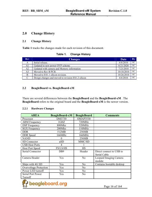
Table 1 tracks the changes made for each revision of this document.<br />
Table 1. <strong>Change</strong> <strong>History</strong><br />
Revision C.1.0<br />
Rev <strong>Change</strong>s Date By<br />
A Initial release. 6/4/2010 GC<br />
A1 Updated to new power OVP scheme 6/21/2020 GC<br />
A2 Updated with camera and Memory information 7/23/2010 GC<br />
A3 Moved to Rev B PCB. 10/18/2010 GC<br />
B Moved to ES1.1 silicon revision. 10/26/2010 GC<br />
C Design changes and moved to revision ES1.2 silicon 4/4/2010 GC<br />
2.2 BeagleBoard vs. BeagleBoard-xM<br />
There are several differences between the BeagleBoard and the BeagleBoard-xM . The<br />
BeagleBoard refers to the original board and the BeagleBoard-xM is the newer version.<br />
2.2.1 Hardware <strong>Change</strong>s<br />
AREA BeagleBoard-xM BeagleBoard Comments<br />
Processor DM3730 OMAP3530<br />
ARM Frequency 1GHZ 720MHz<br />
DSP Frequency 800Mhz 520MHz<br />
SGX Frequency 200Mhz 110MHz<br />
DDR 512MB 256MB<br />
DDR Speed 166MHz 166MHz<br />
NAND 0 256MB<br />
SD Connector uSD MMC/SD<br />
USB Host Ports 4 1<br />
Host Port Speed FS/LS/HS HS<br />
Serial Connector DB9 Header Direct connect to USB to<br />
Serial Cable<br />
Camera Header Yes No Leopard Imaging Camera<br />
module<br />
Ships with 4G SD Yes No Contains bootable desktop<br />
Overvoltage Protection Yes No<br />
Power LED turnoff Yes No<br />
Serial Port Power<br />
Turnoff<br />
Yes No<br />
Page 16 of 164
REF: BB_SRM_xM BeagleBoard-xM System<br />
Reference Manual<br />
MMC3 Expansion<br />
Header<br />
McBSP2 Expansion<br />
Header<br />
2.2.2 Software <strong>Change</strong>s<br />
Following are the changes to the SW.<br />
Yes No<br />
Yes No<br />
Revision C.1.0<br />
o Use of a universal Beagle XLoader and UBoot. These will work on any Beagle<br />
made. They include support for the 512MB DDR and the removal of the NAND<br />
from the –xM board.<br />
o A demo version of the Angstrom desktop distribution.<br />
2.3 –xM Revision A2 vs. –xM Revision A3<br />
There were no major hardware feature changes between the Rev A2 and Rev A3<br />
revisions. Below are the differences between the Rev A2 and Rev A3 revisions.<br />
o Slightly modified PCB layout (Rev B) to correct the following<br />
o <strong>Change</strong>d silkscreen on L12 to R159 to reflect the usage of a resistor<br />
instead of an inductor. Resistor was used on Rev A2. No electrical<br />
difference.<br />
o <strong>Change</strong>d routing on R66 and R68 to make them separate paths instead of<br />
parallel. No electrical difference.<br />
o Added 33 ohm resistor R157 in series with MMC clock line. Not used on<br />
board, only for expansion. No electrical difference.<br />
o Added R158 to allow isolation of drain pin on TPS2141. Loaded with a<br />
zero ohm resistor. No electrical difference.<br />
o Moved DVI_PUP pin to the TPS65950 GPIO2. No SW impact and<br />
Angstrom kernel, however, updated SW can be used to turn off the DVI<br />
interface by taking the pin LO. There may be issues with other<br />
distributions until such time as their code is updated. Electrical change<br />
from A2.<br />
o Added R160 and R155 as a possible future option. Not populated on Rev<br />
A3. No electrical difference.<br />
o <strong>Change</strong>d R120 to 0603 package to align with arts purchased. No electrical<br />
difference.<br />
o Added R156 to remove the required lifting of U18 pin 4. Resistor is not<br />
loaded on Revision A3. No electrical difference.<br />
2.4 –xM Revision A3 vs. –xM Revision B<br />
The only change from Rev –A3 to the Rev B was the replacement of the processor form<br />
ES1.0 to ES1.1. For a detailed description of the issues present in the ES1.1 revision,<br />
Page 17 of 164
REF: BB_SRM_xM BeagleBoard-xM System<br />
Reference Manual<br />
Revision C.1.0<br />
please refer to http://focus.ti.com/lit/er/sprz319a/sprz319a.<strong>pdf</strong> . There are no issues<br />
resolved by ES1.1 that are anticipated to have any impact on the operation of the<br />
BeagleBoard-xM.<br />
2.5 –xM Revision B vs. –xM Revision C<br />
There were seven changes made to the BeagleBoard-xM Rev C version over the Rev B<br />
design.<br />
2.6 Definitions<br />
o Resistor loading was changed to allow for the reading of the Rev C<br />
revision by the SW. GPIO171=0, GPIO_172=1, and GPIO_173=0.<br />
o Replacement of the processor from ES1.1 to ES1.2. For a detailed<br />
description of the issues present in the ES1.2 revision, please refer to<br />
http://focus.ti.com/lit/er/sprz319a/sprz319a.<strong>pdf</strong> . There are no issues<br />
resolved by ES1.2 that are anticipated to have any impact on the operation<br />
of the BeagleBoard-xM. ES1.2 is the latest revision.<br />
o Fixed capacitor footprint in the PCB layout.<br />
o Replaced the microSD connector with a new part. The current part was<br />
targeted for EOL and a new one was required. This required a PCB<br />
footprint change.<br />
o Redesigned the overvoltage protection circuit. We were seeing issues with<br />
a small number of boards being damaged on the TPS2054 USB power<br />
FET, so a new design was implemented. Overall operation is the same as<br />
the original version with te exception that it is now possible to power the<br />
entire board over the USB OTG port. This includes the HUB. Care should<br />
be taken not to add high current devices on the USB ports as that will<br />
cause the host to shut down the USB port,<br />
o <strong>Change</strong>d the default power state of the USB HUB to OFF as an added<br />
layer of protection to make sure the USB power rails are off on initial<br />
power up. This will minimize the initial current drain on the board. SW<br />
can turn on the HUB power as needed by setting the TPS65950<br />
LEDA/VIBRA.P pin LO to turn it on.<br />
o Added the ability for the SW to detect when the board is powered from the<br />
DC supply or the OTG supply. Status is read from GPIO.6 pin on the<br />
TPS65950. If LO, then the board is powered from the DC jack. The HUB<br />
will only work in the DC powered mode so this change allows the board to<br />
know not to try and initialize the USB Host when under OTG power..<br />
Page 18 of 164
REF: BB_SRM_xM BeagleBoard-xM System<br />
Reference Manual<br />
Revision C.1.0<br />
SD- Secure Digital<br />
microSD- Small version of the standard SD card<br />
MDDR- Mobile Dual Data Rate<br />
SDRAM- Synchronous Dynamic Random Access Memory<br />
BeagleBoard- The original version of the board based on the DM3530<br />
BeagleBoard-xM- The newer version of the board based on the DM3730.<br />
.<br />
Page 19 of 164
REF: BB_SRM_xM BeagleBoard-xM System<br />
Reference Manual<br />
Revision C.1.0<br />
BeagleBoard-xM Rev B<br />
System Reference Manual<br />
Revision 0.0<br />
October 18, 2010<br />
Page 20 of 164


