

Chapter 08 Power, Reset, and Clock Management (PRCM).pdf
Chapter 08 Power, Reset, and Clock Management (PRCM).pdf
Chapter 08 Power, Reset, and Clock Management (PRCM).pdf

Create successful ePaper yourself
Turn your PDF publications into a flip-book with our unique Google optimized e-Paper software.
<strong>Chapter</strong> 8<br />
SPRUH73E–October 2011–Revised May 2012<br />
<strong>Power</strong>, <strong>Reset</strong>, <strong>and</strong> <strong>Clock</strong> <strong>Management</strong> (<strong>PRCM</strong>)<br />
This chapter describes the <strong>PRCM</strong> of the device.<br />
Topic ........................................................................................................................... Page<br />
8.1 <strong>Power</strong>, <strong>Reset</strong>, <strong>and</strong> <strong>Clock</strong> <strong>Management</strong> ............................................................... 633<br />
632 <strong>Power</strong>, <strong>Reset</strong>, <strong>and</strong> <strong>Clock</strong> <strong>Management</strong> (<strong>PRCM</strong>) SPRUH73E–October 2011–Revised May 2012<br />
Submit Documentation Feedback<br />
Copyright © 2011–2012, Texas Instruments Incorporated
www.ti.com <strong>Power</strong>, <strong>Reset</strong>, <strong>and</strong> <strong>Clock</strong> <strong>Management</strong><br />
8.1 <strong>Power</strong>, <strong>Reset</strong>, <strong>and</strong> <strong>Clock</strong> <strong>Management</strong><br />
8.1.1 Introduction<br />
The device power-management architecture ensures maximum performance <strong>and</strong> operation time for user<br />
satisfaction (audio/video support) while offering versatile power-management techniques for maximum<br />
design flexibility, depending on application requirements. This introduction contains the following<br />
information:<br />
• <strong>Power</strong>-management architecture building blocks for the device<br />
• State-of-the-art power-management techniques supported by the power-management architecture of<br />
the device<br />
8.1.2 Device <strong>Power</strong>-<strong>Management</strong> Architecture Building Blocks<br />
To provide a versatile architecture supporting multiple power-management techniques, the powermanagement<br />
framework is built with three levels of resource management: clock, power, <strong>and</strong> voltage<br />
management.<br />
These management levels are enforced by defining the managed entities or building blocks of the powermanagement<br />
architecture, called the clock, power, <strong>and</strong> voltage domains. A domain is a group of modules<br />
or subsections of the device that share a common entity (for example, common clock source, common<br />
voltage source, or common power switch). The group forming the domain is managed by a policy<br />
manager. For example, a clock for a clock domain is managed by a dedicated clock manager within the<br />
power, reset, <strong>and</strong> clock management (<strong>PRCM</strong>) module. The clock manager considers the joint clocking<br />
constraints of all the modules belonging to that clock domain (<strong>and</strong>, hence, receiving that clock).<br />
8.1.3 <strong>Clock</strong> <strong>Management</strong><br />
The <strong>PRCM</strong> module along with the control module manages the gating (that is, switching off) <strong>and</strong> enabling<br />
of the clocks to the device modules. The clocks are managed based on the requirement constraints of the<br />
associated modules. The following sections identify the module clock characteristics, management policy,<br />
clock domains, <strong>and</strong> clock domain management<br />
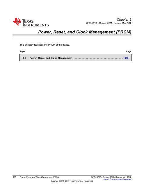
8.1.3.1 Module Interface <strong>and</strong> Functional <strong>Clock</strong>s<br />
Each module within the device has specific clock input characteristic requirements. Based on the<br />
characteristics of the clocks delivered to the modules, the clocks are divided into two categories: interface<br />
clocks <strong>and</strong> functional clocks<br />
<strong>PRCM</strong><br />
<strong>Clock</strong> generator<br />
Figure 8-1. Functional <strong>and</strong> Interface <strong>Clock</strong>s<br />
Interface clock<br />
Device interconnect<br />
Functional clock<br />
The interface clocks have the following characteristics:<br />
X_ICLK<br />
Registers Interconnect<br />
interface<br />
Module X<br />
X_FCLK<br />
prcm-001<br />
• They ensure proper communication between any module/subsystem <strong>and</strong> interconnect.<br />
• In most cases, they supply the system interconnect interface <strong>and</strong> registers of the module.<br />
• A typical module has one interface clock, but modules with multiple interface clocks may also exist<br />
(that is, when connected to multiple interconnect buses).<br />
SPRUH73E–October 2011–Revised May 2012 <strong>Power</strong>, <strong>Reset</strong>, <strong>and</strong> <strong>Clock</strong> <strong>Management</strong> (<strong>PRCM</strong>)<br />
Submit Documentation Feedback<br />
Copyright © 2011–2012, Texas Instruments Incorporated<br />
633
<strong>Power</strong>, <strong>Reset</strong>, <strong>and</strong> <strong>Clock</strong> <strong>Management</strong> www.ti.com<br />
• Interface clock management is done at the device level.<br />
• From the st<strong>and</strong>point of the <strong>PRCM</strong> module, an interface clock is identified by an _ICLK suffix.<br />
Functional clocks have the following characteristics:<br />
• They supply the functional part of a module or subsystem.<br />
• A module can have one or more functional clocks. Some functional clocks are m<strong>and</strong>atory, while others<br />
are optional. A module needs its m<strong>and</strong>atory clock(s) to be operational. The optional clocks are used for<br />
specific features <strong>and</strong> can be shut down without stopping the module activity<br />
• From the st<strong>and</strong>point of the <strong>PRCM</strong> module, a functional clock is distributed directly to the related<br />
modules through a dedicated clock tree. It is identified with an _FCLK suffix<br />
8.1.3.2 Module-Level <strong>Clock</strong> <strong>Management</strong><br />
Each module in the device may also have specific clock requirements. Certain module clocks must be<br />
active when operating in specific modes, or may be gated otherwise. Globally, the activation <strong>and</strong> gating of<br />
the module clocks are managed by the <strong>PRCM</strong> module. Hence, the <strong>PRCM</strong> module must be aware of when<br />
to activate <strong>and</strong> when to gate the module clocks. The <strong>PRCM</strong> module differentiates the clock-management<br />
behavior for device modules based on whether the module can initiate transactions on the device<br />
interconnect (called master module or initiators) or cannot initiate transactions <strong>and</strong> only responds to the<br />
transactions initiated by the master (called slave module or targets). Thus, two hardware-based powermanagement<br />
protocols are used:<br />
• Master st<strong>and</strong>by protocol: <strong>Clock</strong>-management protocol between the <strong>PRCM</strong> <strong>and</strong> master modules.<br />
• Slave idle protocol: <strong>Clock</strong>-management protocol between the <strong>PRCM</strong> <strong>and</strong> slave modules.<br />
8.1.3.2.1 Master St<strong>and</strong>by Protocol<br />
Master st<strong>and</strong>by protocol is used to indicate that a master module must initiate a transaction on the device<br />
interconnect <strong>and</strong> requests specific (functional <strong>and</strong> interface) clocks for the purpose. The <strong>PRCM</strong> module<br />
ensures that the required clocks are active when the master module requests the <strong>PRCM</strong> module to enable<br />
them. This is called a module wake-up transition <strong>and</strong> the module is said to be functional after this<br />
transition completes. Similarly, when the master module no longer requires the clocks, it informs the<br />
<strong>PRCM</strong> module, which can then gate the clocks to the module. The master module is then said to be in<br />
st<strong>and</strong>by mode. Although the protocol is completely hardware-controlled, software must configure the<br />
clock-management behavior for the module. This is done by setting the module register bit field<br />
_SYSCONFIG.MIDLEMODE or _SYSCONFIG.STANDBYMODE. The behavior,<br />
identified by st<strong>and</strong>by mode values, must be configured.<br />
Table 8-1. Master Module St<strong>and</strong>by-Mode Settings<br />
St<strong>and</strong>by Mode Value Selected Mode Description<br />
0x0 Force-st<strong>and</strong>by<br />
0x1 No-st<strong>and</strong>by<br />
The module unconditionally asserts the<br />
st<strong>and</strong>by request to the <strong>PRCM</strong> module,<br />
regardless of its internal operations. The<br />
<strong>PRCM</strong> module may gate the functional<br />
<strong>and</strong> interface clocks to the module. This<br />
mode must be used carefully because it<br />
does not prevent the loss of data at the<br />
time the clocks are gated.<br />
The module never asserts the st<strong>and</strong>by<br />
request to the <strong>PRCM</strong> module. This mode<br />
is safe from a module point of view<br />
because it ensures that the clocks remain<br />
active. However, it is not efficient from a<br />
power-saving perspective because it<br />
never allows the output clocks of the<br />
<strong>PRCM</strong> module to be gated<br />
634 <strong>Power</strong>, <strong>Reset</strong>, <strong>and</strong> <strong>Clock</strong> <strong>Management</strong> (<strong>PRCM</strong>) SPRUH73E–October 2011–Revised May 2012<br />
Submit Documentation Feedback<br />
Copyright © 2011–2012, Texas Instruments Incorporated
www.ti.com <strong>Power</strong>, <strong>Reset</strong>, <strong>and</strong> <strong>Clock</strong> <strong>Management</strong><br />
Table 8-1. Master Module St<strong>and</strong>by-Mode Settings (continued)<br />
St<strong>and</strong>by Mode Value Selected Mode Description<br />
0x2 Smart-st<strong>and</strong>by<br />
The module asserts the st<strong>and</strong>by request<br />
based on its internal activity status. The<br />
st<strong>and</strong>by signal is asserted only when all<br />
ongoing transactions are complete <strong>and</strong><br />
the module is idled. The <strong>PRCM</strong> module<br />
can then gate the clocks to the module.<br />
The module asserts the st<strong>and</strong>by request<br />
based on its internal activity status. The<br />
st<strong>and</strong>by signal is asserted only when all<br />
ongoing transactions are complete <strong>and</strong><br />
the module is idle. The <strong>PRCM</strong> module can<br />
0x3 Smart-st<strong>and</strong>bywakeup-capable mode then gate the clocks to the module. The<br />
module may generate (master-related)<br />
wake-up events when in STANDBY state.<br />
The mode is relevant only if the<br />
appropriate module mwakeup output is<br />
implemented.<br />
The st<strong>and</strong>by status of a master module is indicated by the<br />
CM___CLKCTRL[x]. STBYST bit in the <strong>PRCM</strong> module.<br />
8.1.3.2.2 Slave Idle Protocol<br />
Table 8-2. Master Module St<strong>and</strong>by Status<br />
STBYST Bit Value Description<br />
0x0 The module is functional.<br />
0x1 The module is in st<strong>and</strong>by mode<br />
This hardware protocol allows the <strong>PRCM</strong> module to control the state of a slave module. The <strong>PRCM</strong><br />
module informs the slave module, through assertion of an idle request, when its clocks (interface <strong>and</strong><br />
functional) can be gated. The slave can then acknowledge the request from the <strong>PRCM</strong> module <strong>and</strong> the<br />
<strong>PRCM</strong> module is then allowed to gate the clocks to the module. A slave module is said to be in IDLE state<br />
when its clocks are gated by the <strong>PRCM</strong> module. Similarly, an idled slave module may need to be<br />
wakened because of a service request from a master module or as a result of an event (called a wake-up<br />
event; for example, interrupt or DMA request) received by the slave module. In this situation the <strong>PRCM</strong><br />
module enables the clocks to the module <strong>and</strong> then deasserts the idle request to signal the module to wake<br />
up. Although the protocol is completely hardware-controlled, software must configure the clockmanagement<br />
behavior for the slave module. This is done by setting the module register bit field<br />
_SYSCONFIG. SIDLEMODE or _SYSCONFIG. IDLEMODE. The behavior, listed in<br />
the Idle Mode Value column, must be configured by software.<br />
Table 8-3. Module Idle Mode Settings<br />
Idle Mode Value Selected Mode Description<br />
0x0 Force-idle<br />
The module unconditionally acknowledges<br />
the idle request from the <strong>PRCM</strong> module,<br />
regardless of its internal operations. This<br />
mode must be used carefully because it<br />
does not prevent the loss of data at the<br />
time the clock is switched off.<br />
The module never acknowledges any idle<br />
request from the <strong>PRCM</strong> module. This<br />
mode is safe from a module point of view<br />
because it ensures that the clocks remain<br />
0x1 No-idle active. However, it is not efficient from a<br />
power-saving perspective because it does<br />
not allow the <strong>PRCM</strong> module output clock<br />
to be shut off, <strong>and</strong> thus the power domain<br />
to be set to a lower power state.<br />
SPRUH73E–October 2011–Revised May 2012 <strong>Power</strong>, <strong>Reset</strong>, <strong>and</strong> <strong>Clock</strong> <strong>Management</strong> (<strong>PRCM</strong>)<br />
Submit Documentation Feedback<br />
Copyright © 2011–2012, Texas Instruments Incorporated<br />
635
<strong>Power</strong>, <strong>Reset</strong>, <strong>and</strong> <strong>Clock</strong> <strong>Management</strong> www.ti.com<br />
Table 8-3. Module Idle Mode Settings (continued)<br />
Idle Mode Value Selected Mode Description<br />
0x2 Smart-idle<br />
The module acknowledges the idle<br />
request basing its decision on its internal<br />
activity. Namely, the acknowledge signal<br />
is asserted only when all pending<br />
transactions, interrupts, or direct memory<br />
access (DMA) requests are processed.<br />
This is the best approach to efficient<br />
system power management.<br />
The module acknowledges the idle<br />
request basing its decision on its internal<br />
wakeup-capable mode activity. Namely,<br />
the acknowledge signal is asserted only<br />
when all pending transactions, interrupts,<br />
or DMA requests are processed. This is<br />
0x3 Smart-idle wakeup-capable mode the best approach to efficient system<br />
power management. The module may<br />
generate (IRQ- or DMA-request-related)<br />
wake-up events when in IDLE state. The<br />
mode is relevant only if the appropriate<br />
module swakeup output(s) is<br />
implemented.<br />
The idle status of a slave module is indicated by the CM___CLKCTRL[x]<br />
IDLEST bit field in the <strong>PRCM</strong> module.<br />
Table 8-4. Idle States for a Slave Module<br />
IDLEST Bit VALUE Idle Status Description<br />
0x0 Functional<br />
0x1 In transition<br />
The module is fully functional.The<br />
interface <strong>and</strong> functional clocks are active.<br />
The module is performing a wake-up or a<br />
sleep transition<br />
The module interface clock is idled. The<br />
0x2 Interface idle module may remain functional if using a<br />
separate functional clock<br />
0x3 Full idle<br />
The module is fully idle. The interface <strong>and</strong><br />
functional clocks are gated.<br />
For the idle protocol management on the <strong>PRCM</strong> module side, the behavior of the <strong>PRCM</strong> module is<br />
configured in the CM___CLKCTRL[x] MODULEMODE bit field. Based on the<br />
configured behavior, the <strong>PRCM</strong> module asserts the idle request to the module unconditionally (that is,<br />
immediately when the software requests).<br />
Table 8-5. Slave Module Mode Settings in <strong>PRCM</strong><br />
MODULEMODE Bit VALUE Selected Mode Description<br />
0x0 Disabled<br />
0x1 Reserved NA<br />
The <strong>PRCM</strong> module unconditionally asserts<br />
the module idle request. This request<br />
applies to the gating of the functional <strong>and</strong><br />
interface clocks to the module. If<br />
acknowledged by the module, the <strong>PRCM</strong><br />
module can gate all clocks to the module<br />
(that is, the module is completely<br />
disabled)..<br />
636 <strong>Power</strong>, <strong>Reset</strong>, <strong>and</strong> <strong>Clock</strong> <strong>Management</strong> (<strong>PRCM</strong>) SPRUH73E–October 2011–Revised May 2012<br />
Submit Documentation Feedback<br />
Copyright © 2011–2012, Texas Instruments Incorporated
www.ti.com <strong>Power</strong>, <strong>Reset</strong>, <strong>and</strong> <strong>Clock</strong> <strong>Management</strong><br />
Table 8-5. Slave Module Mode Settings in <strong>PRCM</strong> (continued)<br />
MODULEMODE Bit VALUE Selected Mode Description<br />
0x2 Enabled<br />
0x3 Reserved NA<br />
This mode applies to a module when the<br />
<strong>PRCM</strong> module manages its interface <strong>and</strong><br />
functional clocks. The functional clock to<br />
the module remains active unconditionally,<br />
while the <strong>PRCM</strong> module automatically<br />
asserts/deasserts the module idle request<br />
based on the clock-domain transitions. If<br />
acknowledged by the module, the <strong>PRCM</strong><br />
module can gate only the interface clock<br />
to the module.<br />
In addition to the IDLE <strong>and</strong> STANDBY protocol, <strong>PRCM</strong> offers also the possibility to manage optional<br />
clocks, through a direct SW control: “OptFclken” bit from programming register.<br />
Table 8-6. Module <strong>Clock</strong> Enabling Condition<br />
<strong>Clock</strong> Enabling<br />
<strong>Clock</strong> associated with<br />
STANDBY protocol<br />
AND<br />
OR<br />
<strong>Clock</strong> Domain is ready<br />
MSt<strong>and</strong>by is de-asserted<br />
Mwakeup is asserted<br />
<strong>Clock</strong> Domain is ready<br />
<strong>Clock</strong> associated with IDLE<br />
protocol, as interface clock<br />
AND<br />
OR<br />
Idle status = FUNCT<br />
Idle status = TRANS<br />
<strong>Clock</strong> Domain is ready<br />
SWakeup is asserted<br />
<strong>Clock</strong> associated with IDLE<br />
protocol, as functional clock<br />
AND<br />
OR<br />
Idle status = FUNCT<br />
Idle status = IDLE<br />
Idle status = TRANS<br />
8.1.3.3 <strong>Clock</strong> Domain<br />
Optional clock AND<br />
<strong>Clock</strong> domain is ready<br />
OptFclken=Enabled ('1')<br />
SWakeup is asserted<br />
A clock domain is a group of modules fed by clock signals controlled by the same clock manager in the<br />
<strong>PRCM</strong> module By gating the clocks in a clock domain, the clocks to all the modules belonging to that<br />
clock domain can be cut to lower their active power consumption (that is, the device is on <strong>and</strong> the clocks<br />
to the modules are dynamically switched to ACTIVE or INACTIVE (GATED) states). Thus, a clock domain<br />
allows control of the dynamic power consumption of the device. The device is partitioned into multiple<br />
clock domains, <strong>and</strong> each clock domain is controlled by an associated clock manager within the <strong>PRCM</strong><br />
module. This allows the <strong>PRCM</strong> module to individually activate <strong>and</strong> gate each clock domain of the device<br />
SPRUH73E–October 2011–Revised May 2012 <strong>Power</strong>, <strong>Reset</strong>, <strong>and</strong> <strong>Clock</strong> <strong>Management</strong> (<strong>PRCM</strong>)<br />
Submit Documentation Feedback<br />
Copyright © 2011–2012, Texas Instruments Incorporated<br />
637
<strong>Power</strong>, <strong>Reset</strong>, <strong>and</strong> <strong>Clock</strong> <strong>Management</strong> www.ti.com<br />
Sleep condition<br />
CM_a<br />
Figure 8-2. Generic <strong>Clock</strong> Domain<br />
CLK1<br />
<strong>PRCM</strong><br />
FCLK2<br />
CM_b<br />
Module 1 Module 2<br />
Figure above is an example of two clock managers: CM_a <strong>and</strong> CM_b. Each clock manager manages a<br />
clock domain. The clock domain of CM_b is composed of two clocks: a functional clock (FCLK2) <strong>and</strong> an<br />
interface clock (ICLK1), while the clock domain of CM_a consists of a clock (CLK1) that is used by the<br />
module as a functional <strong>and</strong> interface clock. The clocks to Module 2 can be gated independently of the<br />
clock to Module 1, thus ensuring power savings when Module 2 is not in use. The <strong>PRCM</strong> module lets<br />
software check the status of the clock domain functional clocks. The CM__CLKSTCTRL[x]<br />
CLKACTIVITY_ bit in the <strong>PRCM</strong> module identifies the state of the functional<br />
clock(s) within the clock domain. Table shows the possible states of the functional clock.<br />
IDLE_TRANSITION<br />
ICLK1<br />
prcm-002<br />
Table 8-7. <strong>Clock</strong> Domain Functional <strong>Clock</strong> States<br />
CLKACTIVITY BIT Value Status Description<br />
0x0 Gated<br />
0x1 Active<br />
8.1.3.3.1 <strong>Clock</strong> Domain-Level <strong>Clock</strong> <strong>Management</strong><br />
All modules IDLE/STANDBY<br />
All domain clocks gated<br />
ACTIVE INACTIVE<br />
Domain sleep conditions not satisfied<br />
A wake-up request is received<br />
The functional clock of the clock domain is<br />
inactive<br />
The functional clock of the clock domain is<br />
running<br />
The domain clock manager can automatically (that is, based on hardware conditions) <strong>and</strong> jointly manage<br />
the interface clocks within the clock domain. The functional clocks within the clock domain are managed<br />
through software settings. A clock domain can switch between three possible states: ACTIVE,<br />
IDLE_TRANSITION, <strong>and</strong> INACTIVE. Figure 8-3 shows the sleep <strong>and</strong> wake-up transitions of the clock<br />
domain between ACTIVE <strong>and</strong> INACTIVE states.<br />
Figure 8-3. <strong>Clock</strong> Domain State Transitions<br />
638 <strong>Power</strong>, <strong>Reset</strong>, <strong>and</strong> <strong>Clock</strong> <strong>Management</strong> (<strong>PRCM</strong>) SPRUH73E–October 2011–Revised May 2012<br />
Submit Documentation Feedback<br />
Copyright © 2011–2012, Texas Instruments Incorporated<br />
prcm-003
www.ti.com <strong>Power</strong>, <strong>Reset</strong>, <strong>and</strong> <strong>Clock</strong> <strong>Management</strong><br />
Table 8-8. <strong>Clock</strong> Domain States<br />
State Description<br />
ACTIVE<br />
IDLE_TRANSITION<br />
Every nondisabled slave module (that is, those whose<br />
MODULEMODE value is not set to disabled) is put out of IDLE<br />
state.<br />
All interface clocks to the nondisabled slave modules in the<br />
clock domain are provided. All functional <strong>and</strong> interface clocks to<br />
the active master modules (that is, not in STANDBY) in the clock<br />
domain are provided. All enabled optional clocks to the modules<br />
in the clock domain are provided.<br />
This is a transitory state.<br />
Every master module in the clock domain is in STANDBY state.<br />
Every idle request to all the slave modules in the clock domain is<br />
asserted. The functional clocks to the slave module in enabled<br />
state (that is, those whose MODULEMODE values are set to<br />
enabled) remain active.<br />
All enabled optional clocks to the modules in the clock domain<br />
are provided.<br />
All clocks within the clock domain are gated.<br />
Every slave module in the clock is in IDLE state <strong>and</strong> set to<br />
disabled.<br />
INACTIVE Every slave module in the clock domain (that is, those whose<br />
MODULEMODE is set to disabled) is in IDLE state <strong>and</strong> set to<br />
disabled.<br />
Every optional functional clock in the clock domain is gated<br />
Each clock domain transition behavior is managed by an associated register bit field in the CM__CLKSTCTRL[x] CLKTRCTRL <strong>PRCM</strong> module<br />
Table 8-9. <strong>Clock</strong> Transition Mode Settings<br />
CLKTRCTRL Bit Value Selected Mode Description<br />
8.1.4 <strong>Power</strong> <strong>Management</strong><br />
0x0 Reserved NA<br />
A software-forced sleep transition. The<br />
0x1 SW_SLEEP transition is initiated when the associated<br />
hardware conditions are satisfied<br />
0x2 SW_WKUP<br />
0x3 Reserved NA<br />
A software-forced clock domain wake-up<br />
transition is initiated<br />
The <strong>PRCM</strong> module manages the switching on <strong>and</strong> off of the power supply to the device modules. To<br />
minimize device power consumption, the power to the modules can be switched off when they are not in<br />
use. Independent power control of sections of the device allows the <strong>PRCM</strong> module to turn on <strong>and</strong> off<br />
specific sections of the device without affecting the others.<br />
8.1.4.1 <strong>Power</strong> Domain<br />
A power domain is a section (that is, a group of modules) of the device with an independent <strong>and</strong> dedicated<br />
power manager (see Figure). A power domain can be turned on <strong>and</strong> off without affecting the other parts of<br />
the device.<br />
SPRUH73E–October 2011–Revised May 2012 <strong>Power</strong>, <strong>Reset</strong>, <strong>and</strong> <strong>Clock</strong> <strong>Management</strong> (<strong>PRCM</strong>)<br />
Submit Documentation Feedback<br />
Copyright © 2011–2012, Texas Instruments Incorporated<br />
639
<strong>Power</strong>, <strong>Reset</strong>, <strong>and</strong> <strong>Clock</strong> <strong>Management</strong> www.ti.com<br />
Vdd<br />
Varray<br />
<strong>PRCM</strong><br />
Memory<br />
array<br />
Memory array<br />
power switch<br />
Memory bank<br />
Figure 8-4. Generic <strong>Power</strong> Domain Architecture<br />
Memory<br />
array<br />
Memory logic<br />
power switch<br />
Memory<br />
logic<br />
PM<br />
Memory Logic<br />
Logic power<br />
switch<br />
Flip-flop<br />
logic<br />
Logic power<br />
switch<br />
Flip-flop<br />
logic<br />
<strong>Power</strong> domain<br />
To minimize device power consumption, the modules are grouped into power domains. A power domain<br />
can be split into a logic area <strong>and</strong> a memory area.<br />
8.1.4.2 <strong>Power</strong> Domain <strong>Management</strong><br />
Table 8-10. States of a Memory Area in a <strong>Power</strong> Domain<br />
State Description<br />
ON The memory array is powered <strong>and</strong> fully functional<br />
OFF The memory array is powered down<br />
Table 8-11. States of a Logic Area in a <strong>Power</strong> Domain<br />
State Description<br />
ON Logic is fully powered<br />
prcm-0<strong>08</strong><br />
OFF Logic power switches are off. All the logic (DFF) is lost<br />
The power manager associated with each power domain is assigned the task of managing the domain<br />
power transitions. It ensures that all hardware conditions are satisfied before it can initiate a power domain<br />
transition from a source to a target power state<br />
Table 8-12. <strong>Power</strong> Domain Control <strong>and</strong> Status Registers<br />
Register/Bit Field Type Description<br />
PM__PWRSTCTRL[1:0]<br />
POWERSTATE<br />
PM__PWRSTST[1:0]<br />
POWERSTATEST<br />
PM__PWRSTST[2]<br />
LOGICSTATEST<br />
Selects the target power state of the<br />
Control power domain among OFF, ON, or<br />
RETENTION.<br />
Identifies the current state of the power<br />
Status domain. It can be OFF, ON, or<br />
RETENTION.<br />
Identifies the current state of the logic<br />
Status area in the power domain. It can be OFF<br />
or ON.<br />
640 <strong>Power</strong>, <strong>Reset</strong>, <strong>and</strong> <strong>Clock</strong> <strong>Management</strong> (<strong>PRCM</strong>) SPRUH73E–October 2011–Revised May 2012<br />
Submit Documentation Feedback<br />
Copyright © 2011–2012, Texas Instruments Incorporated
www.ti.com <strong>Power</strong>, <strong>Reset</strong>, <strong>and</strong> <strong>Clock</strong> <strong>Management</strong><br />
Table 8-12. <strong>Power</strong> Domain Control <strong>and</strong> Status Registers (continued)<br />
Register/Bit Field Type Description<br />
PM__PWRSTST[5:4]<br />
MEMSTATEST<br />
8.1.4.2.1 <strong>Power</strong>-<strong>Management</strong> Techniques<br />
Identifies the current state of the memory<br />
Status area in the power domain. It can be OFF,<br />
ON, or RETENTION<br />
The following section describes the state-of-the-art power-management techniques supported by the<br />
device.<br />
8.1.4.2.1.1 Adaptive Voltage Scaling<br />
AVS is a power-management technique based in Smart Reflex that is used for automatic control of the<br />
operating voltages of the device to reduce active power consumption. With Smart Reflex, power-supply<br />
voltage is adapted to silicon performance, either statically (based on performance points predefined in the<br />
manufacturing process of a given device) or dynamically (based on the temperature-induced real-time<br />
performance of the device). A comparison of these predefined performance points to the real-time on-chip<br />
measured performance determines whether to raise or lower the power-supply voltage. AVS achieves the<br />
optimal performance/power trade-off for all devices across the technology process spectrum <strong>and</strong> across<br />
temperature variation. The device voltage is automatically adapted to maintain performance of the device<br />
8.1.4.3 <strong>Power</strong> Modes<br />
The following power modes are for easy reference applicable for typical use cases. The design does not<br />
restrict these to be the only modes. In order of the lowest power to the highest power, these modes are<br />
named RTC-Only, DeepSleep0, DeepSleep1, DeepSleep2, St<strong>and</strong>by <strong>and</strong> Active. All voltage supplies must<br />
be maintained for the each of the Deep Sleep, St<strong>and</strong>by <strong>and</strong> Active modes. In Active mode, all power<br />
domains are ON. In RTC mode, only the supplies to the RTC subsystem are supplied.<br />
The contents of SDRAM are preserved in any of the Deep Sleep/St<strong>and</strong>by modes. This is done by placing<br />
SDRAM in self-refresh prior to entering Deep Sleep.<br />
Use Case<strong>Power</strong> Mode Application state<br />
Table 8-13. Typical <strong>Power</strong> Modes<br />
Only RTC voltage domain is alive.<br />
RTC-Only Optionally, SDRAM can be kept in selfrefresh<br />
which will reduce the boot time.<br />
DeepSleep0<br />
<strong>Power</strong> Domain States& Supply<br />
Voltages<br />
VDD_MPU = 0v<br />
VDD_CORE = 0v<br />
VDDS_RTC supply is active.<br />
Optionally, IO supplies can be left ON<br />
PD_PER peripheral & CortexA8 / MPU<br />
register information will be lost.<br />
On-chip peripheral register (context)<br />
information of PD_PER domain needs to<br />
be saved by application to SDRAM before<br />
Master Oscillator = OFF<br />
VDD_MPU = 0.95v<br />
VDD_CORE = 0.95v<br />
PD_WKUP = ON<br />
entering this mode. PD_MPU = OFF<br />
SDRAM is in self-refresh. For wakeup,<br />
boot ROM executes <strong>and</strong> branches to<br />
peripheral context restore followed by<br />
system resume.<br />
PD_PER = OFF<br />
PD_GFX = OFF<br />
All IO supplies & RTC supplies are ON<br />
On-chip peripheral registers are<br />
Master Oscillator = OFF<br />
preserved. VDD_MPU = 0.95v<br />
CortexA8 context/registers are lost <strong>and</strong> VDD_CORE = 0.95v<br />
DeepSleep1<br />
hence application needs to save them to<br />
MPU Subsystem or L3 OCMC RAM or<br />
SDRAM before entering DeepSleep.<br />
PD_WKUP = ON<br />
PD_MPU = OFF<br />
SDRAM is in self-refresh.<br />
PD_PER = ON<br />
For wakeup, boot ROM executes <strong>and</strong> PD_GFX = OFF<br />
branch to system resume. All IO supplies & RTC supplies are ON<br />
SPRUH73E–October 2011–Revised May 2012 <strong>Power</strong>, <strong>Reset</strong>, <strong>and</strong> <strong>Clock</strong> <strong>Management</strong> (<strong>PRCM</strong>)<br />
Submit Documentation Feedback<br />
Copyright © 2011–2012, Texas Instruments Incorporated<br />
641
<strong>Power</strong>, <strong>Reset</strong>, <strong>and</strong> <strong>Clock</strong> <strong>Management</strong> www.ti.com<br />
Use Case<strong>Power</strong> Mode Application state<br />
Table 8-13. Typical <strong>Power</strong> Modes (continued)<br />
<strong>Power</strong> Domain States& Supply<br />
Voltages<br />
DeepSleep2 Everything is preserved including SDRAM.<br />
Master Oscillator = OFF<br />
VDD_MPU = 0.95v<br />
VDD_CORE = 0.95v<br />
PD_WKUP = ON<br />
PD_MPU = ON<br />
PD_PER = ON<br />
PD_GFX = OFF<br />
All IO supplies & RTC supplies are ON<br />
Master Oscillator = ON<br />
One PLL is ON.<br />
VDD_MPU = 0.95v<br />
VDD_CORE = OPP50<br />
PD_WKUP = ON<br />
Everything is preserved including SDRAM. PD_MPU = ON<br />
St<strong>and</strong>by Only required module clocks are enabled,<br />
rest are clock gated. PD_PER = ON<br />
PD_GFX = OFF<br />
All IO supplies & RTC supplies are ON<br />
If more PLLs /power domains/ modules<br />
are required, the power will increase<br />
accordingly.<br />
Active All Features<br />
8.1.4.3.1 Active<br />
Master Oscillator = ON<br />
One or more PLLs are ON<br />
VDD_MPU = ON<br />
VDD_CORE = ON<br />
PD_WKUP = ON<br />
PD_MPU = ON<br />
PD_PER = ON<br />
PD_GGX = ON<br />
In Active mode, the supply to all voltage rails must be maintained. All power domains come up in ON state<br />
<strong>and</strong> the device is fully functional.<br />
8.1.4.3.2 St<strong>and</strong>by<br />
In St<strong>and</strong>by mode, the supply to all voltage rails must be maintained. The power consumption can be<br />
minimized if the supply voltage placed at its minimum operating voltage. Using Software the required<br />
PLL’s are made active depending upon wakeup or use case requirements <strong>and</strong> the rest are placed in low<br />
power bypass modes. All non-essential IP blocks are powered down. A peripheral interrupt to CortexM3,<br />
will cause it to un-clock gate the A8 after which A8 services the pending interrupt. SDRAM contents are<br />
preserved. This is useful for quick st<strong>and</strong>by/resume kind of application.<br />
8.1.4.3.3 Deepsleep0<br />
In DeepSleep0 mode, the supply to all voltage rails are maintained, only the PD_RTC <strong>and</strong> PD_WKUP<br />
power domains are ON. The master crystal oscillator is disabled. PD_MPU is OFF. The contents of<br />
OCMC RAM are preserved. Additionally the contents of the SDRAM are preserved by placing the SDRAM<br />
in self-refresh. Activity on wake up peripherals via wake up events enables the master crystal oscillator<br />
using the oscillator control circuit. Also, the wake up events interrupt CortexM3.<br />
642 <strong>Power</strong>, <strong>Reset</strong>, <strong>and</strong> <strong>Clock</strong> <strong>Management</strong> (<strong>PRCM</strong>) SPRUH73E–October 2011–Revised May 2012<br />
Submit Documentation Feedback<br />
Copyright © 2011–2012, Texas Instruments Incorporated
www.ti.com <strong>Power</strong>, <strong>Reset</strong>, <strong>and</strong> <strong>Clock</strong> <strong>Management</strong><br />
8.1.4.3.4 Deepsleep1<br />
In DeepSleep1 mode, the supply to all voltage rails are maintained, the PD_RTC, PD_WKUP & PD_PER<br />
power domains are ON. The PD_GFX power domain is OFF (but could be optionally ON at the cost of<br />
more power). The master crystal oscillator is disabled. The contents of internal SRAM are preserved.<br />
Additionally the contents of the SDRAM are preserved by placing the SDRAM in self-refresh. Activity on<br />
wake up peripherals via wake up events enables the master crystal oscillator using the oscillator control<br />
circuit. Also, the wake up events interrupt CortexM3.<br />
8.1.4.3.5 Deepsleep2<br />
In DeepSleep2 mode, the supply to all voltage rails are maintained, all power domains are ON. The<br />
PD_GFX power domain is OFF (but could be optionally ON at the cost of more power). The master crystal<br />
oscillator is disabled. The contents of internal SRAM are preserved. Additionally the contents of the<br />
SDRAM are preserved by placing the SDRAM in self-refresh. Activity on wake up peripherals via wake<br />
events enables the master crystal oscillator using the oscillator control circuit. Also, the wake events up<br />
events interrupt CortexM3.<br />
8.1.4.3.6 RTC-Only<br />
The following diagram gives a high level view of system which implements the RTC-only mode.<br />
AM335x<br />
RTC/<br />
Backup<br />
battery<br />
domain<br />
Figure 8-5. High Level System View for RTC-only Mode<br />
ext_wakeup0<br />
SoC-<strong>Power</strong>-on-reset<br />
SoC-<strong>Power</strong>-on-supplies<br />
pmic_pwr_enable<br />
RTC-<strong>Power</strong>-on-reset<br />
RTC <strong>Power</strong> supply<br />
Internal FSM/control<br />
Wakeup<br />
Enable/NSleep<br />
PMIC<br />
Main supply<br />
Pushbutton<br />
Backup supply<br />
If RTC-only mode is not required or implemented by the end application, RTC power supply<br />
(CAP_VDD_RTC) may be connected to VDD_CORE or a separate 1.1-V power source. In addition, the<br />
RTC power-on reset (RTC_PWRONRSTn) can be connected to the SoC power-on reset (PWRONRSTn)<br />
if their power domains are at the same voltage level (i.e., VDDSHV6 is the same voltage as VDDS_RTC).<br />
The RTC battery backup domain consists of RTCSS (subsystem), a dedicated on-chip 32.768 Hz crystal<br />
oscillator <strong>and</strong> I/Os associated with RTCSS — pmic_pwr_enable & ext_wakeup0.<br />
In RTC-only mode, only the RTC power supply is expected to be ON. All the remaining supplies are<br />
expected to be OFF. For SDRAM to be in self-refresh during this mode, the CKE pin of the DDR interface<br />
needs to have a pulldown on the board.<br />
SPRUH73E–October 2011–Revised May 2012 <strong>Power</strong>, <strong>Reset</strong>, <strong>and</strong> <strong>Clock</strong> <strong>Management</strong> (<strong>PRCM</strong>)<br />
Submit Documentation Feedback<br />
Copyright © 2011–2012, Texas Instruments Incorporated<br />
643
<strong>Power</strong>, <strong>Reset</strong>, <strong>and</strong> <strong>Clock</strong> <strong>Management</strong> www.ti.com<br />
8.1.4.4 Main Oscillator Control During Deep Sleep<br />
The Deepsleep oscillator circuit is used to control the main oscillator by disabling it during deep sleep <strong>and</strong><br />
enabling during active/wakeup. By default during reset, the oscillator is enabled <strong>and</strong> the oscillator control<br />
circuit comes up disabled (in-active).In order to activate the oscillator control circuit for deepsleep,<br />
DSENABLE bit of DEEPSLEEP_CTRL register must set. Once this is set <strong>and</strong> whenever wake M3 enters<br />
st<strong>and</strong>by, the oscillator control will disable the oscillator causing the clock to be shut OFF. Any async event<br />
from the wakeup sources will cause the oscillator control to re-enable the oscillator after a period of<br />
DSCOUNT configured in DEEPSLEEP_CTRL register.<br />
8.1.4.5 Wakeup Sources/Events<br />
Following events will wake up the device from Deep sleep(low power) modes. These are part of the<br />
Wakeup <strong>Power</strong> domain <strong>and</strong> remain always ON.<br />
• GPIO0 bank<br />
• dmtimer1_1ms (timer based wakeup)<br />
• USB2PHY (USB resume signaling from suspend) – Both USB ports supported.<br />
• TSC (touch screen controller, ADC monitor functions )<br />
• UART0 (Infra-red support)<br />
• I2C0<br />
These wake events apply on any of the deep sleep modes <strong>and</strong> st<strong>and</strong>by mode.<br />
8.1.4.6 Functional Sequencing for <strong>Power</strong> <strong>Management</strong> with Cortex M3<br />
The AM335x device constains a dedicated Cortex M3 processor to h<strong>and</strong>le the power management<br />
transitions. It is part of the Wake up <strong>Power</strong> domain (PD_WKUP). Implementing the <strong>Power</strong> modes are part<br />
of the MPU <strong>and</strong> Cortex A8 processors.<br />
The power management sequence kicks off with Cortex A8 MPU executing a WFI instruction with the<br />
following steps:<br />
1. During Active power mode, the Cortex A8 MPU executes a WFI instruction to enter IDLE mode.<br />
2. Cortex M3 gets an interrupts <strong>and</strong> gets active, It powers down the MPU power domain( if required).<br />
3. Registers interrupt for the Wake up peripheral(which is listed in Wake up sources in previous section).<br />
4. Executes WFI <strong>and</strong> goes into idle state.<br />
5. The wake up event triggers an interrupt to Cortex M3 system <strong>and</strong> it wakes up the Cortex A8 MPU.<br />
Generally, A8 <strong>and</strong> CortexM3 are not expected to be active at the same time CortexM3 along with <strong>PRCM</strong><br />
is the power manager primarily for PD_MPU <strong>and</strong> PD_PER. Other power domains (e.g., PD_GFX) may be<br />
h<strong>and</strong>led directly using Cortex A8 MPU software. Figure 8-6 gives a system level view of the <strong>Power</strong><br />
management system between Cortex A8 MPU <strong>and</strong> Cortex M3.<br />
644 <strong>Power</strong>, <strong>Reset</strong>, <strong>and</strong> <strong>Clock</strong> <strong>Management</strong> (<strong>PRCM</strong>) SPRUH73E–October 2011–Revised May 2012<br />
Submit Documentation Feedback<br />
Copyright © 2011–2012, Texas Instruments Incorporated
www.ti.com <strong>Power</strong>, <strong>Reset</strong>, <strong>and</strong> <strong>Clock</strong> <strong>Management</strong><br />
Figure 8-6. System Level View of <strong>Power</strong> <strong>Management</strong> of Cortex A8 MPU <strong>and</strong> Cortex M3<br />
INTR2<br />
WKUP<br />
PD_GFX<br />
PD_MPU<br />
(Cortex-A8)<br />
MSG3<br />
16KB unified RAM<br />
8KB DRAM<br />
Cortex-M3 subsystem<br />
TXEV RXEV<br />
Legend:<br />
PD_PER<br />
MBX<br />
INTR3<br />
Cortex-<br />
M3<br />
MSG1<br />
INTR1<br />
System power clock manager<br />
Interrupt<br />
Alternate Interrupt/Event<br />
s/w message<br />
Alternate s/w message<br />
Data flow<br />
Bus<br />
Interconnect<br />
Bus<br />
MSG3<br />
Table 8-14. M3 Interrupts 1–3<br />
IP/Peripherals<br />
<strong>Power</strong><br />
connect/<br />
disconnect<br />
<strong>Power</strong><br />
Idle<br />
<strong>PRCM</strong><br />
Control<br />
Interrupt Name Interrupt Number in M3 Explanation<br />
INTR1 (<strong>PRCM</strong>_M3_IRQ1) 16<br />
<strong>Power</strong><br />
Idle<br />
Generated by <strong>PRCM</strong> when MPU power domain is<br />
clock gated.<br />
INTR2 (<strong>PRCM</strong>_M3_IRQ2) 34 Generated by wakeup events<br />
SPRUH73E–October 2011–Revised May 2012 <strong>Power</strong>, <strong>Reset</strong>, <strong>and</strong> <strong>Clock</strong> <strong>Management</strong> (<strong>PRCM</strong>)<br />
Submit Documentation Feedback<br />
Copyright © 2011–2012, Texas Instruments Incorporated<br />
645
<strong>Power</strong>, <strong>Reset</strong>, <strong>and</strong> <strong>Clock</strong> <strong>Management</strong> www.ti.com<br />
Table 8-14. M3 Interrupts 1–3 (continued)<br />
Interrupt Name Interrupt Number in M3 Explanation<br />
INTR3 (MBINT0) 31 Mailbox interrupt to M3<br />
8.1.4.6.1 Periodic Idling of Cortex A8 MPU<br />
To implement Cortex A8 MPU periodic ON/OFF in the use case, the control flow could be implemented<br />
according to the following steps:<br />
1. Cortex A8 MPU executes WFI instruction<br />
2. Any peripheral interrupt in any of the next steps will trigger a wake interrupt to CortexM3 via MPU<br />
Subsystem’s WKUP signal (INTR2 shown on the diagram). Cortex M3 powers down the<br />
MPU(PD_MPU)<br />
3. On receiving an interrupt Cortex M3 switches ON the MPU power domain by turning on PD_MPU<br />
4. Cortex M3 goes into idle mode using WFI instruction<br />
8.1.4.6.2 Sleep Sequencing<br />
This section gives the system level guidelines for sleep sequencing. The guidelines can serve as an<br />
example for implementing the sleep mode sequencing. The user can opt to implement a sequence with<br />
certain steps interchanged between the MPU <strong>and</strong> Cortex M3 processor.<br />
1. Application saves context of peripherals to memories supporting retention <strong>and</strong> DDR – this step is only<br />
required for Deepsleep0.<br />
2. MPU OCMC_RAM remains in retention<br />
3. Unused power domains are turned OFF - program clock/power domains PWRSTCTRL, save contexts<br />
etc<br />
4. Software populates L3_OCMC_RAM for wakeup restoration viz Save EMIF settings, public restoration<br />
pointers, etc.<br />
5. Execute WFI from SRAM<br />
6. Any peripheral interrupt will trigger a wake interrupt to CortexM3 via Cortex A8 MPU’s WKUP signal<br />
(INTR2 shown on the diagram).<br />
7. After MPU power domain is clock gated <strong>PRCM</strong> will provide an interrupt to CortexM3 (using INTR1<br />
shown in the block diagram)<br />
8. CortexM3 starts execution as follows:<br />
• CortexM3 configures PLL / HSDIVIDER power down States (bypass modes). During Idle bypass<br />
mode (low power mode) the PLL / HSDIVIDER goes into bypass <strong>and</strong> provides the clock outputs<br />
directly from the oscillator clock.<br />
• CortexM3 disables IP/Peripheral/Interconnects based on MSG1/MSG2/MSG3<br />
sconnect/disconnect/Idle protocol kicks off <strong>and</strong> completes<br />
• <strong>PRCM</strong> turns OFF power domains based on MSG1/MSG2/MSG3 Only applicable for DeepSleep0 &<br />
DeepSleep1.<br />
• CortexM3 lowers the PMIC voltage to OPP50 voltage<br />
• CortexM3 configures I/O PADs for lowest power as dictated by CortexA8 using MSG2/MSG3<br />
• CortexM3 goes into WFI<br />
9. Hardware oscillator control circuit disables the oscillator once CortexM3 goes into WFI<br />
8.1.4.6.3 Wakeup Sequencing<br />
This section gives the guidelines for Wakeup sequencing.<br />
1. One of the wakeup event triggers (which was configured during the sleep sequencing) will initiate a<br />
wakeup sequence<br />
2. The wake up event will switch on the oscillator (if it was configured to go OFF during sleep)<br />
646 <strong>Power</strong>, <strong>Reset</strong>, <strong>and</strong> <strong>Clock</strong> <strong>Management</strong> (<strong>PRCM</strong>) SPRUH73E–October 2011–Revised May 2012<br />
Submit Documentation Feedback<br />
Copyright © 2011–2012, Texas Instruments Incorporated
www.ti.com <strong>Power</strong>, <strong>Reset</strong>, <strong>and</strong> <strong>Clock</strong> <strong>Management</strong><br />
3. The wake up event will also trigger interrupt to Cortex M3<br />
4. On the wakeup event due to interrupt Cortex M3 execute the following<br />
• Restore the voltages to normal Operating voltage<br />
• Enable PLL locking<br />
• Cortex M3 will switch ON the power domains <strong>and</strong>/or enable clocks for PD_PER<br />
• Cortex M3 will switch ON the power domains <strong>and</strong>/or enable clocks for PD_MPU<br />
• Executes WFI<br />
5. Cortex A8 MPU starts executing from ROM reset vector<br />
6. Restore the application context(only for Deep sleep 0)<br />
8.1.5 <strong>PRCM</strong> Module Overview<br />
The <strong>PRCM</strong> is structured using the architectural concepts presented in the 5000x <strong>Power</strong> <strong>Management</strong><br />
Framework. This framework provides:<br />
A set of modular, re-usable FSM blocks to be assembled into the full clock <strong>and</strong> power management<br />
mechanism. A register set <strong>and</strong> associated programming model. Functional sub-block definitions for clock<br />
management, power management, system clock source generation, <strong>and</strong> master clock generation.<br />
The device supports an enhanced power management scheme based on four functional power domains:<br />
Generic Domains<br />
• WAKEUP<br />
• MPU<br />
• PER<br />
• RTC<br />
The <strong>PRCM</strong> provides the following functional features:<br />
• Software configurable for direct, automatic, or a combination thereof, functional power domain state<br />
transition control<br />
• Device power-up sequence control<br />
• Device sleep / wake-up sequence control<br />
• Centralized reset generation <strong>and</strong> management<br />
• Centralized clock generation <strong>and</strong> management<br />
The <strong>PRCM</strong> modules implement these general functional interfaces:<br />
• OCP configuration ports<br />
• Direct interface to device boundary<br />
• <strong>Power</strong> switch control signals<br />
• Device control signals<br />
• <strong>Clock</strong>s control signals<br />
• <strong>Reset</strong>s signals<br />
• A set of power management protocol signals for each module to control <strong>and</strong> monitor st<strong>and</strong>by, idle <strong>and</strong><br />
wake-up modes (CM <strong>and</strong> PRM)<br />
• Emulation signals<br />
8.1.5.1 Interface Descriptions<br />
This section lists <strong>and</strong> shortly describes the different interfaces that allow <strong>PRCM</strong> to communicate with other<br />
modules or external devices.<br />
SPRUH73E–October 2011–Revised May 2012 <strong>Power</strong>, <strong>Reset</strong>, <strong>and</strong> <strong>Clock</strong> <strong>Management</strong> (<strong>PRCM</strong>)<br />
Submit Documentation Feedback<br />
Copyright © 2011–2012, Texas Instruments Incorporated<br />
647
<strong>Power</strong>, <strong>Reset</strong>, <strong>and</strong> <strong>Clock</strong> <strong>Management</strong> www.ti.com<br />
8.1.5.1.1 OCP Interfaces<br />
The <strong>PRCM</strong> has 1 target OCP interfaces, compliant with respect to the OCP/IP2 st<strong>and</strong>ard. The OCP port,<br />
for the <strong>PRCM</strong> module is used to control power, reset <strong>and</strong> wake-up <strong>Management</strong>.<br />
8.1.5.1.2 OCP Slave Interfaces<br />
<strong>PRCM</strong> implements a 32-bit OCP target interface compliant to the OCP/IP2.0 st<strong>and</strong>ard.<br />
8.1.5.1.3 <strong>Power</strong> Control Interface<br />
The Device does has power domain switches over the device, this interface provides <strong>PRCM</strong> control over<br />
power domain switches <strong>and</strong> receives responses from the power domains which indicate the switch status.<br />
It also controls the isolation signals. The control for power domain switches will be latched in <strong>PRCM</strong><br />
Status Registers<br />
8.1.5.1.4 Device Control Interface<br />
This interface provides PRM management of several device-level features which are not specific to any<br />
single power domain. This PRM interface controls signals to/from the device for global control:<br />
• Device Type coding<br />
• IOs isolation control<br />
8.1.5.1.5 <strong>Clock</strong>s Interface<br />
This interface gathers all clock inputs <strong>and</strong> outputs managed by <strong>PRCM</strong> modules.<br />
8.1.5.1.6 <strong>Reset</strong>s Interface<br />
This interface gathers all resets inputs <strong>and</strong> outputs managed by <strong>PRCM</strong> module.<br />
8.1.5.1.7 Modules <strong>Power</strong> <strong>Management</strong> Control Interface<br />
Modules or subsystems in the device are split over 2 categories:<br />
• Initiator: an initiator is a module able to generate traffic on the device interconnects (typically:<br />
processors, MMU, EDMA).<br />
• Target: a target is a module that cannot generate traffic on the device interconnects, but that can<br />
generate interrupts or DMA request to the system (typically: peripherals). <strong>PRCM</strong> h<strong>and</strong>les a power<br />
management h<strong>and</strong>shake protocol with each module or sub-system. This protocol allows performing<br />
proper clock <strong>and</strong> power transition taking into account each module activity or state.<br />
8.1.5.1.8 Initiator Modules Interface<br />
<strong>PRCM</strong> module h<strong>and</strong>le all initiator modules power management interfaces: MSt<strong>and</strong>by signal MWait signal<br />
8.1.5.1.9 Targets Modules Interface<br />
<strong>PRCM</strong> module h<strong>and</strong>le all target modules power management interfaces: SIdleReq signal SIdleAck signal<br />
FCLKEN signal <strong>PRCM</strong> module h<strong>and</strong>les all target modules wake-up: SWakeup signal<br />
Note: USB Support for SWakeUp<br />
8.1.6 <strong>Clock</strong> Generation <strong>and</strong> <strong>Management</strong><br />
<strong>PRCM</strong> provides a centralized control for the generation, distribution <strong>and</strong> gating of most clocks in the<br />
device. <strong>PRCM</strong> gathers external clocks <strong>and</strong> internally generated clocks for distribution to the other modules<br />
in the device. <strong>PRCM</strong> manages the system clock generation<br />
8.1.6.1 Terminology<br />
The <strong>PRCM</strong> produces 2 types of clock:<br />
648 <strong>Power</strong>, <strong>Reset</strong>, <strong>and</strong> <strong>Clock</strong> <strong>Management</strong> (<strong>PRCM</strong>) SPRUH73E–October 2011–Revised May 2012<br />
Submit Documentation Feedback<br />
Copyright © 2011–2012, Texas Instruments Incorporated
www.ti.com <strong>Power</strong>, <strong>Reset</strong>, <strong>and</strong> <strong>Clock</strong> <strong>Management</strong><br />
Interface clocks: these clocks primarily provide clocking for the system interconnect modules <strong>and</strong> the<br />
portions of device's functional modules which interface to the system interconnect modules. In most<br />
cases, the interface clock supplies the functional module's system interconnect interface <strong>and</strong> registers. For<br />
some modules, interface clock is also used as functional clock. In this document, interface clocks are<br />
represented by blue lines.<br />
Functional clock: this clock supplies the functional part of a module or a sub-system. In some cases, a<br />
module or a subsystem may require several functional clocks: 1 or several main functional clock(s), 1 or<br />
several optional clock(s). A module needs its main clock(s) to be operational. Optional clocks are used for<br />
specific features <strong>and</strong> can be shutdown without stopping the module<br />
8.1.6.2 <strong>Clock</strong> Structure<br />
To generate high-frequency clocks, the device supports multiple on-chip DPLLs controlled directly by the<br />
<strong>PRCM</strong> module. They are of two types of PLLs, referred to ADPLLS <strong>and</strong> ADPLLLJ throughout this<br />
document.<br />
The ADPLLS module is used for the Core, Display, ARM Subsystem <strong>and</strong> DDR PLLs<br />
The ADPLLLJ module is used for the peripheral functional clocks<br />
The device has two reference clocks which are generated by on-chip oscillators or externally. These are<br />
for the main clock tree <strong>and</strong> RTC block, respectively.<br />
In the case of an external oscillator, a clock can directly be connected to XTALIN pin <strong>and</strong> the oscillator will<br />
be put in bypass mode. The 32-Khz crystal oscillator is controlled <strong>and</strong> configurable by RTC IP. This device<br />
also contains an on-chip RC oscillator. This oscillator is not configurable but may be enabled or disabled<br />
through the Control Module RCOSC_CTRL register.<br />
The main oscillator on the device (see <strong>Chapter</strong> 26, Initialization, for possible frequencies) produces the<br />
master high frequency clock CLK_M_OSC.<br />
8.1.6.3 ADPLLS<br />
The ADPLLS is a high resolution frequency synthesizer PLL with built in level shifters which allows the<br />
generation of frequencies up to 2 Ghz. ADPLLS has a predivide feature which allows user to divide, for<br />
instance, a 24- or 26-MHz reference clock to 1-MHz <strong>and</strong> then multiply up to 2-GHz maximum.<br />
All PLLs will come-up in bypass mode at reset. SW needs to program all the pll settings appropriately <strong>and</strong><br />
then wait for PLL to be locked. For more details, see the configuration procedure for each PLL.<br />
The following PLLs are:<br />
• MPU PLL<br />
• Core PLL<br />
• Display PLL<br />
• DDR PLL<br />
SPRUH73E–October 2011–Revised May 2012 <strong>Power</strong>, <strong>Reset</strong>, <strong>and</strong> <strong>Clock</strong> <strong>Management</strong> (<strong>PRCM</strong>)<br />
Submit Documentation Feedback<br />
Copyright © 2011–2012, Texas Instruments Incorporated<br />
649
<strong>Power</strong>, <strong>Reset</strong>, <strong>and</strong> <strong>Clock</strong> <strong>Management</strong> www.ti.com<br />
REFCLK<br />
FBCLK<br />
CLKINP<br />
1/(N+1)<br />
7 bits<br />
PFD Multiplier DAC<br />
1/M.f<br />
SSC sigmadelta<br />
½<br />
(1 bit)<br />
The ADPLLS has three input clocks:<br />
• CLKINP: Reference input clock<br />
Figure 8-7. ADPLLS<br />
CLKINPHIF<br />
1/(N2+1)<br />
(4 bits)<br />
CLKINPULOW<br />
1/M2<br />
(5 bits)<br />
CLKINPHIFSEL<br />
• CLKINPULOW: Low frequency input clock for bypass mode only.<br />
• CLKINPHIF: High Frequency Input <strong>Clock</strong> for post-divider M3<br />
The ADPLLS has four output clocks:<br />
• CLKOUTHIF: High Frequency Output <strong>Clock</strong> from Post divider M3<br />
• CLKOUTX2: Secondary 2x Output<br />
• CLKOUT: Primary output clock<br />
• CLKDCOLDO: Oscillator (DCO) output clock with no bypass<br />
The DPLL has two internal clocks:<br />
ULOWCLKEN<br />
½<br />
(1 bit)<br />
1/M3<br />
(5 bits)<br />
• REFCLK (Internal reference clock): This is generated by dividing the input clock CLKINP by the<br />
programmed value N+1. The entire loop of the PLL runs on the REFCLK.<br />
Here, REFCLK = CLKINP/(N+1).<br />
• BCLK: Bus clock which is used for programming the various settings using registers<br />
8.1.6.3.1 <strong>Clock</strong> Functions<br />
Table 8-15. Output <strong>Clock</strong>s in Locked Condition<br />
Pin Name Frequency Comments<br />
REGM4XEN='0'<br />
CLKOUT [M / (N+1)] * CLKINP * [1/M2]<br />
CLKOUTX2 2 * [M / (N+1)] * CLKINP * [1/M2]<br />
CLKDCOLDO 2 * [M / (N+1)] * CLKINP<br />
CLKOUTHIF<br />
CLKOUTX2<br />
BYPASS_INT<br />
CLKOUT<br />
CLKDCOLDO<br />
CLKOUTHIF<br />
CLKINPHIF / M3 CLKINPHIFSEL='1'<br />
2 * [M / (N+1)] * CLKINP * [1/M3] CLKINPHIFSEL='0'<br />
REGM4XEN='1'<br />
CLKOUT [4M / (N+1)] * CLKINP * [1/M2]<br />
650 <strong>Power</strong>, <strong>Reset</strong>, <strong>and</strong> <strong>Clock</strong> <strong>Management</strong> (<strong>PRCM</strong>) SPRUH73E–October 2011–Revised May 2012<br />
Submit Documentation Feedback<br />
Copyright © 2011–2012, Texas Instruments Incorporated
www.ti.com <strong>Power</strong>, <strong>Reset</strong>, <strong>and</strong> <strong>Clock</strong> <strong>Management</strong><br />
Table 8-15. Output <strong>Clock</strong>s in Locked Condition (continued)<br />
Pin Name Frequency Comments<br />
CLKOUTX2 2 * [4M / (N+1)] * CLKINP * [1/M2]<br />
CLKDCOLDO 2 * [4M / (N+1)] * CLKINP<br />
CLKOUTHIF<br />
CLKINPHIF / M3 CLKINPHIFSEL='1'<br />
2 * [4M / (N+1)] * CLKINP * [1/M3] CLKINPHIFSEL='0'<br />
Table 8-16. Output <strong>Clock</strong>s Before Lock <strong>and</strong> During Relock Modes<br />
Pin Name Frequency Comments<br />
CLKOUT<br />
CLKOUTX2<br />
CLKDCOLDO Low<br />
CLKOUTHIF<br />
CLKINP / (N2+1) ULOWCLKEN='0'<br />
CLKINPULOW ULOWCLKEN='1'<br />
CLKINP / (N2+1) ULOWCLKEN='0'<br />
CLKINPULOW ULOWCLKEN='1'<br />
CLKINPHIF/M3 ULOWCLKEN='1'<br />
Low ULOWCLKEN='0'<br />
Note: Since M3 divider is running on the internal LDO domain, in the case when CLKINPHIFSEL=’1’,<br />
CLKOUTHIF could be active only when internal LDO is ON. Hence, whenever LDOPWDN goes low to<br />
high to powerdown LDO (happens when TINITZ activated / when entering slow relock bypass mode),<br />
output CLKOUTHIF will glitch <strong>and</strong> stop. To avoid this glitch, it is recommended to gate CLKOUTHIF using<br />
control CLKOUTHIFEN before asserting TINITZ / entering any slow relock bypass mode Frequency<br />
Range (MHz)<br />
See the device-specific data manual for details on operating performance points (OPPs) supported by<br />
your device.<br />
8.1.6.4 ADPLLLJ (Low Jitter DPLL)<br />
The ADPLLLJ is a low jitter PLL with a 2-GHz maximum output. ADPLLLJ has a predivide feature which<br />
allows user to divide, for instance, a 20-MHz or 27-MHz reference clock to 1MHz <strong>and</strong> then multiply up to<br />
2-GHz maximum.<br />
All PLLs will come-up in bypass mode at reset. SW needs to program all the PLL settings appropriately<br />
<strong>and</strong> then wait for PLL to be locked. For more details, see the configuration procedure for each PLL.<br />
SPRUH73E–October 2011–Revised May 2012 <strong>Power</strong>, <strong>Reset</strong>, <strong>and</strong> <strong>Clock</strong> <strong>Management</strong> (<strong>PRCM</strong>)<br />
Submit Documentation Feedback<br />
Copyright © 2011–2012, Texas Instruments Incorporated<br />
651
<strong>Power</strong>, <strong>Reset</strong>, <strong>and</strong> <strong>Clock</strong> <strong>Management</strong> www.ti.com<br />
REFCLK<br />
FBCLK<br />
CLKINP<br />
1/(N+1)<br />
8 bits<br />
PFD Multiplier<br />
Sigma<br />
delta<br />
1/M.f<br />
8 bits<br />
SSC<br />
DAC<br />
The Peripheral PLL belongs to type ADPLLLJ:<br />
The DPLL has two input clocks:<br />
• CLKINP: Reference input clock<br />
• CLKINPULOW: Bypass input clock.<br />
The DPLL has two internal clocks:<br />
Figure 8-8. Basic Structure of the ADPLLLJ<br />
SDCLK<br />
HS1: 2–1 GHz<br />
HS1<br />
HS2<br />
HS2: 1–0.5 GHz<br />
1/(SD)<br />
8 bits<br />
SELFREQDCO<br />
ULOWCLKEN<br />
1/M2<br />
7 bits<br />
1/(N2 + 1)<br />
4 bits<br />
CLKINP<br />
CLKOUTLDO<br />
CLKOUT<br />
CLKINPULOW<br />
• REFCLK (Internal reference clock): This is generated by dividing the input clock CLKINP by the<br />
programmed value N+1. The entire loop of the PLL runs on the REFCLK.<br />
Here, REFCLK = CLKINP/(N+1).<br />
CLKDCOLDO<br />
• CLKDCO (Internal Oscillator clock.):This is the raw clock directly out of the digitally controlled oscillator<br />
(DCO) before the post-divider. The PLL output clock is synthesized by an internal oscillator which is<br />
phase locked to the refclk. There are two oscillators built within ADPLLLJ. The oscillators are user<br />
selectable based on the synthesized output clock frequency requirement. In locked condition, CLKDCO<br />
= CLKINP *[M/(N+1)].<br />
The DPLL has three external output clocks:<br />
• CLKOUTLDO: Primary output clock in VDDLDOOUT domain. Bypass option not available on this<br />
output.<br />
CLKOUTLDO = (M / (N+1))*CLKINP*(1/M2)<br />
• CLKOUT:<br />
Primary output clock on digital core domain<br />
CLKOUT = (M / (N+1))*CLKINP*(1/M2)<br />
• CLKDCOLDO:<br />
Oscillator (DCO) output clock before post-division in VDDLDOOUT domain. Bypass option is not<br />
available on this output.<br />
CLKDCOLDO = (M / (N+1))*CLKINP.<br />
652 <strong>Power</strong>, <strong>Reset</strong>, <strong>and</strong> <strong>Clock</strong> <strong>Management</strong> (<strong>PRCM</strong>) SPRUH73E–October 2011–Revised May 2012<br />
Submit Documentation Feedback<br />
Copyright © 2011–2012, Texas Instruments Incorporated
www.ti.com <strong>Power</strong>, <strong>Reset</strong>, <strong>and</strong> <strong>Clock</strong> <strong>Management</strong><br />
All clock outputs of the DPLL can be gated. The Control module provides the DPLL with a clock gating<br />
control signal to enable or disable the clock, <strong>and</strong> the DPLL provides the <strong>PRCM</strong> module with a clock<br />
activity status signal to let the <strong>PRCM</strong> module hardware know when the clock is effectively running or<br />
effectively gated. Output clock gating control for various clockouts:<br />
CLKOUTEN/CLKOUTLDOEN/CLKDCOLDOEN.<br />
8.1.6.4.1 <strong>Clock</strong> Functions<br />
Table 8-17. Output <strong>Clock</strong>s in Locked Condition<br />
Pin Name Frequency<br />
CLKOUT [M /(N+1)] * CLKINP * [1/M2]<br />
CLKOUTLDO [M /(N+1)] * CLKINP * [1/M2]<br />
CLKDCOOUT [M /(N+1)] * CLKINP<br />
Table 8-18. Output <strong>Clock</strong>s Before Lock <strong>and</strong> During Relock Modes<br />
Pin Name Frequency Comments<br />
CLKOUT<br />
CLKDCOLDO LOW<br />
CLKOUTLDO LOW<br />
8.1.6.5 M2 <strong>and</strong> N2 Change On-the-Fly<br />
CLKINP/(N2+1) ULOWCLKEN=’0’<br />
CLKINPLOW ULOWCLKEN=’1’<br />
The dividers M2 <strong>and</strong> N2 are designed to change on the fly <strong>and</strong> provide a glitch-free frequency switch from<br />
the old to new frequencies. In other words, they can be changed while the PLL is in a locked condition,<br />
without having to switch to bypass mode. A status toggle bit will give an indication if the new divisor was<br />
accepted. These dividers can also be changed in bypass mode, <strong>and</strong> the new divisor value will be reflected<br />
on output after the PLL relocks. For more details, see the PLL configuration procedures for each PLL.<br />
8.1.6.6 Core PLL Description<br />
The Core PLL provides the source for a majority of the device infrastructure <strong>and</strong> peripheral clocks. The<br />
Core PLL comprises an ADPLLS with HSDIVIDER <strong>and</strong> additional dividers <strong>and</strong> muxes located in the<br />
<strong>PRCM</strong> as shown in Figure 8-9.<br />
SPRUH73E–October 2011–Revised May 2012 <strong>Power</strong>, <strong>Reset</strong>, <strong>and</strong> <strong>Clock</strong> <strong>Management</strong> (<strong>PRCM</strong>)<br />
Submit Documentation Feedback<br />
Copyright © 2011–2012, Texas Instruments Incorporated<br />
653
<strong>Power</strong>, <strong>Reset</strong>, <strong>and</strong> <strong>Clock</strong> <strong>Management</strong> www.ti.com<br />
Master<br />
Osc<br />
(CLK_M_OSC)<br />
ALT_CLK1<br />
ALT_CLK2<br />
Test.CDR (via P1500)<br />
<strong>Reset</strong> default = 0<br />
ALT_CLK3<br />
Core PLL<br />
(ADPLLS)<br />
CLKINPULOW<br />
ULOWCLKEN<br />
CLKINP<br />
CLKDCOLDO<br />
CLKOUT<br />
CLKOUTx2<br />
CLKOUTHIF<br />
0<br />
1<br />
2<br />
HSDIVIDER<br />
M6<br />
CLKINPHIFLDO<br />
CLKINBYPASS<br />
Figure 8-9. Core PLL<br />
M4<br />
M5<br />
CORE_CLKOUTM6<br />
PER_CLKOUTM2<br />
(192 MHz)<br />
CORE_CLKOUTM4<br />
(200 MHz)<br />
DISP_CLKOUT<br />
CORE_CLKOUTM5<br />
(250 MHz)<br />
<strong>PRCM</strong><br />
/2, /5<br />
1<br />
A<br />
0<br />
/1, /2<br />
(0) (1)<br />
ALT_CLKs are to be used for internal test purpose <strong>and</strong> should not be used in functional mode.<br />
C<br />
0<br />
1<br />
/2<br />
B<br />
D<br />
0<br />
1<br />
/2<br />
/10<br />
To DDR,<br />
Display, MPU<br />
PLLs<br />
SGX CORECLK<br />
L3S_CLK<br />
L4_PER_CLK<br />
L4_WKUP_CLK<br />
L3F_CLK<br />
L4F_CLK<br />
PRU-ICSS_IEP_CLK,<br />
Debugss_clka<br />
PRU-ICSS OCP_CLKL<br />
CPTS_RFT_CLK<br />
(Enet switch<br />
IEEE1588)<br />
MHZ_250_CLK<br />
(RGMII gigabit)<br />
MHZ_125_CLK<br />
(Enet switch bus<br />
interface)<br />
MHZ_50_CLK<br />
(RGMII 100 Mbps<br />
<strong>and</strong> RMII)<br />
MHZ_5_CLK<br />
(RGMII 10 Mbps)<br />
654 <strong>Power</strong>, <strong>Reset</strong>, <strong>and</strong> <strong>Clock</strong> <strong>Management</strong> (<strong>PRCM</strong>) SPRUH73E–October 2011–Revised May 2012<br />
Submit Documentation Feedback<br />
Copyright © 2011–2012, Texas Instruments Incorporated<br />
E
www.ti.com <strong>Power</strong>, <strong>Reset</strong>, <strong>and</strong> <strong>Clock</strong> <strong>Management</strong><br />
Table 8-19. PLL <strong>and</strong> <strong>Clock</strong> Frequences<br />
Mux Select Register Bit Section 9.2.4.4<br />
A <strong>PRCM</strong>.CLKSEL_GFX_FCLK[1]<br />
B <strong>PRCM</strong>.CLKSEL_GFX_FCLK[0]<br />
C <strong>PRCM</strong>.CLKSEL_PRU-ICSS_OCP_CLK[0]<br />
D <strong>PRCM</strong>.CM_CPTS_RFT_CLKSEL[0]<br />
E TEST.CDR (via P1500)<br />
Table 8-20 gives the typical PLL <strong>and</strong> clock frequencies. The HSDIVIDER is used to generate three divided<br />
clocks M4, M5 & M6. M4 & M5 are nominally 200 & 250 MHz, respectively.<br />
CLOCK Source<br />
CLKDCOLDO (PLL<br />
Lock frequency)<br />
Table 8-20. Core PLL Typical Frequencies (MHz)<br />
<strong>Power</strong>-On-<strong>Reset</strong> /<br />
HSDIVIDER Bypass<br />
OPP100 OPP50 (1)<br />
DIV Freq DIV Value Freq (MHz) DIV Value Freq (MHz)<br />
APLLS - - - 2000 - 100<br />
HSDIVIDER-<br />
CORE_CLKOUTM4 - Mstr Xtal 10 200 1 100<br />
M4<br />
L3F_CLK, L4F_CLK,<br />
PRU-ICSS IEP CLK,<br />
DebugSS clka,<br />
SGX.MEMCLK,<br />
SGX.SYSCLK<br />
CORE_CLKO<br />
UTM4<br />
- Mstr Xtal - 200 - 100<br />
L4_PER, L4_WKUP<br />
CORE_CLKO<br />
UTM4<br />
2 Mstr Xtal / 2 2 100 2 50<br />
SGX CORECLK<br />
CORE_CLKO<br />
UTM4<br />
1 Mstr Xtal 1<br />
2<br />
200<br />
100<br />
1<br />
2<br />
100<br />
50<br />
HSDIVIDER-<br />
CORE_CLKOUTM5 - Mstr Xtal 8 250 1 100<br />
M5<br />
MHZ_250_CLK (Gigabit CORE_CLKO<br />
RGMII) UTM5<br />
- NA - 250 - NA<br />
MHZ_125_CLK<br />
CORE_CLKO<br />
(Ethernet Switch Bus 2 Mstr Xtal / 2 2 125 2 50<br />
UTM5<br />
Clk)<br />
MHZ_50_CLK (100<br />
CORE_CLKO<br />
mbps RGMII or 10/100 5 Mstr Xtal / 5 5 50 2 50<br />
UTM5<br />
RMII)<br />
MHZ_5_CLK (10 mbps<br />
RGMII)<br />
MHZ_50_CLK 10 Mstr Xtal / 50 10 5 10 5<br />
HSDIVIDER<br />
CORE_CLKOUTM6 - Mstr Xtal 2 500 1 100<br />
M6<br />
(1) Not all interfaces <strong>and</strong> peripheral modules are available in OPP50. For more information, see the device specific datasheet.<br />
The ADPLLS module supports two different bypass modes via their internal MNBypass mode <strong>and</strong> their<br />
external Low <strong>Power</strong> Idle bypass mode. The PLLs are in the MNBypass mode after power-on reset <strong>and</strong><br />
can be configured by software to enter Low <strong>Power</strong> Idle bypass mode for power-down.<br />
When the Core PLL is configured in bypass mode, the HSDIVIDER enters bypass mode <strong>and</strong> the<br />
CLKINBYPASS input is driven on the M4, M5, <strong>and</strong> M6 outputs. CLKINBYPASS defaults to the master<br />
oscillator input (typically 24 MHz).<br />
SPRUH73E–October 2011–Revised May 2012 <strong>Power</strong>, <strong>Reset</strong>, <strong>and</strong> <strong>Clock</strong> <strong>Management</strong> (<strong>PRCM</strong>)<br />
Submit Documentation Feedback<br />
Copyright © 2011–2012, Texas Instruments Incorporated<br />
655
<strong>Power</strong>, <strong>Reset</strong>, <strong>and</strong> <strong>Clock</strong> <strong>Management</strong> www.ti.com<br />
Table 8-21. Bus Interface <strong>Clock</strong>s<br />
SGX530 (MEMCLK & SYSCLK), LCDC, MPU Subsystem,<br />
L3F_CLK GEMAC Switch (Ethernet), DAP, PRU-ICSS, EMIF, TPTC,<br />
TPCC, OCMC RAM, DEBUGSS<br />
L3S_CLK USB, TSC, GPMC, MMCHS2, McASP0, McASP1<br />
L4_PER_CLK<br />
L4_WKUP_CLK<br />
8.1.6.6.1 Core PLL Configuration<br />
DCAN0, DCAN1<br />
DMTIMER2, DMTIMER3, DMTIMER4, DMTIMER5, DMTIMER6,<br />
DMTIMER7<br />
eCAP/eQEP/ePWM0, eCAP/eQEP/ePWM1,<br />
eCAP/eQEP/ePWM2, eFuse<br />
ELM, GPIO1, GPIO2, GPIO3<br />
I2C1, I2C2, IEEE1500, LCD, Mailbox0<br />
McASP0, McASP1<br />
MMCHS0, MMCHS1, OCP Watchpoint,<br />
SPI0, SPI1, Spinlock<br />
UART1, UART2, UART3, UART4, UART5<br />
ADC_TSC, <strong>Clock</strong> Manager, Control Module<br />
DMTIMER0, DMTIMER1_1MS, GPIO0<br />
I2C0, M3UMEM, M3DMEM, SmartReflex0, SmartReflex1<br />
UART0, WDT1<br />
1. Switch PLL to bypass mode by setting CM_CLKMODE_DPLL_CORE.DPLL_EN to 0x4.<br />
2. Wait for CM_IDLEST_DPLL_CORE.ST_MN_BYPASS = 1 to ensure PLL is in bypass<br />
(CM_IDLEST_DPLL_CORE.ST_DPLL_CLK should also change to 0 to denote the PLL is unlocked).<br />
3. Configure Multiply <strong>and</strong> Divide values by setting CM_CLKSEL_DPLL_CORE.DPLL_MULT <strong>and</strong><br />
DPLL_DIV to the desired values.<br />
4. Configure M4, M5 <strong>and</strong> M6 dividers by setting HSDIVIDER_CLKOUT1_DIV bits in<br />
CM_DIV_M4_DPLL_CORE,CM_DIV_M5_DPLL_CORE, <strong>and</strong> CM_DIV_M6_DPLL_CORE to the<br />
desired values.<br />
5. Switch over to lock mode by setting CM_CLKMODE_DPLL_CORE.DPLL_EN to 0x7.<br />
6. Wait for CM_IDLEST_DPLL_CORE.ST_DPLL_CLK = 1 to ensure PLL is locked<br />
(CM_IDLEST_DPLL_CORE.ST_MN_BYPASS should also change to 0 to denote the PLL is out of<br />
bypass mode).<br />
Note: M4, M5, <strong>and</strong> M6 dividers can also be changed on-the-fly so that there is no need to put the PLL in<br />
bypass <strong>and</strong> back to lock mode. After changing CM_DIV_Mx_DPLL_CORE.DPLL_CLKOUT_DIV, check<br />
CM_DIV_Mx_DPLL_CORE.DPLL_HSDIVIDER_CLKOUT1_DIVCHACK for a toggle (a change from 0 to 1<br />
or 1 to 0) to see if the change was acknowledged by the PLL.<br />
8.1.6.7 Peripheral PLL Description<br />
The Per PLL provides the source for peripheral functional clocks. The Per PLL comprises an ADPLLLJ<br />
<strong>and</strong> additional dividers <strong>and</strong> muxes located in the <strong>PRCM</strong> as shown<br />
656 <strong>Power</strong>, <strong>Reset</strong>, <strong>and</strong> <strong>Clock</strong> <strong>Management</strong> (<strong>PRCM</strong>) SPRUH73E–October 2011–Revised May 2012<br />
Submit Documentation Feedback<br />
Copyright © 2011–2012, Texas Instruments Incorporated
www.ti.com <strong>Power</strong>, <strong>Reset</strong>, <strong>and</strong> <strong>Clock</strong> <strong>Management</strong><br />
Master<br />
Osc<br />
(CLK_M_OSC)<br />
ALT_CLK1<br />
ALT_CLK2<br />
TEST.CDR (via P1500)<br />
<strong>Reset</strong> default = 0<br />
0<br />
1<br />
2<br />
Per PLL<br />
(ADPLLLJ)<br />
CLKINP<br />
Figure 8-10. Peripheral PLL Structure<br />
CLKDCOLDO<br />
CLKINPULOW<br />
ULOWCLKEN<br />
ULOWPRIORITY<br />
CLKOUT<br />
PER_CLKOUTM2<br />
(192 MHz)<br />
Controls<br />
USB_PHY_CLK (960 MHz)<br />
<strong>PRCM</strong><br />
/4<br />
/2<br />
/2<br />
(96 MHz)<br />
(48 MHz)<br />
CLK_48<br />
CLK_24<br />
(32,768 Hz)<br />
ALT_CLKs are to be used for internal test purpose <strong>and</strong> should not be used in functional mode.<br />
*<strong>Reset</strong> default zero<br />
To USB PHY<br />
PRU_ICSS_UART_CLK<br />
MMC_CLK<br />
SPI_CLK<br />
UART_CLK<br />
I2C_CLK<br />
/732.4219<br />
/366.2109<br />
CLK_32KHZ<br />
CONTROL_CLK32K<br />
DIVRATIO_CTRL[0]*<br />
To DDR, Disp, MPU PLLs bypass<br />
clocking <strong>PRCM</strong> SGX clock mux<br />
The PLL is locked at 960 MHz. The PLL output is divided by the M2 divider to generate a 192-MHz<br />
CLKOUT. This clock is gated in the <strong>PRCM</strong> to form the PRU-ICSS UART clock. There is a /2 divider to<br />
create 96 MHz for MMC_CLK. The clock is also divided within the <strong>PRCM</strong> by a fixed /4 divider to create a<br />
48-MHz clock for the SPI, UART <strong>and</strong> I2C modules. The 48-MHz clock is further divided by a fixed /2<br />
divider <strong>and</strong> a fixed /732.4219 divider to create an accurate 32.768-KHz clock for Timer <strong>and</strong> debounce use.<br />
<strong>Clock</strong> Source<br />
PLL Lock<br />
frequency<br />
Table 8-22. Per PLL Typical Frequencies (MHz)<br />
<strong>Power</strong>-On-<strong>Reset</strong> / PLL<br />
Bypass<br />
OPP100 OPP50<br />
DIV Value Freq DIV Value Freq (MHz) DIV Value Freq (MHz)<br />
PLL - - - 960 - 96<br />
USB_PHY_CL CLKDCOLDO - Held Low - 960 - N/A<br />
K<br />
PER_CLKOU<br />
TM2<br />
CLKOUT of<br />
ADPLLLJ<br />
CLKOUT uses<br />
PLL’s M2<br />
Divider when<br />
PLL is locked<br />
<strong>and</strong> PLL’s N2<br />
divider when<br />
PLL Bypass<br />
N2 is 0 on<br />
power-onreset<br />
Mstr Xtal/<br />
(N2+1)<br />
5 192 1 96<br />
PER_CLKOU Mstr Xtal/<br />
MMC_CLK 2 2 96 2 48<br />
TM2 ((N2+1)*2)<br />
SPI_CLK,<br />
PER_CLKOU Mstr Xtal/<br />
UART_CLK, 4 4 48 4 24<br />
TM2 ((N2+1)*4)<br />
I2C_CLK<br />
CLK_24 CLK_48 2 CLK_48 /2 2 24 2 12<br />
CLK_24<br />
CLK_24 /<br />
CLK_32KHZ (output of 732.4219 732.4219 0.032768 366.2109 0.032768<br />
<br />
CLK_48/2)<br />
SPRUH73E–October 2011–Revised May 2012 <strong>Power</strong>, <strong>Reset</strong>, <strong>and</strong> <strong>Clock</strong> <strong>Management</strong> (<strong>PRCM</strong>)<br />
Submit Documentation Feedback<br />
Copyright © 2011–2012, Texas Instruments Incorporated<br />
0<br />
1<br />
657
<strong>Power</strong>, <strong>Reset</strong>, <strong>and</strong> <strong>Clock</strong> <strong>Management</strong> www.ti.com<br />
The ADPLLLJ module supports two different bypass modes via their internal MNBypass mode <strong>and</strong> their<br />
external Low <strong>Power</strong> Idle bypass mode. The PLLs are in the MNBypass mode after power-on reset <strong>and</strong><br />
can be configured by software to enter Low <strong>Power</strong> Idle bypass mode for power-down.<br />
The PER PLL can use the Low <strong>Power</strong> Idle bypass mode. When the internal bypass mode is selected, the<br />
CLKOUT output is driven by CLKINP/(N2+1) where N2 is driven by the <strong>PRCM</strong>. CLKINP defaults to the<br />
master oscillator input (typically 24 MHz)<br />
8.1.6.7.1 Configuring the Peripheral PLL<br />
The following steps detail how to configure the peripheral PLL.<br />
1. Switch PLL to bypass mode by setting CM_CLKMODE_DPLL_PER.DPLL_EN to 0x4.<br />
2. Wait for CM_IDLEST_DPLL_PER.ST_MN_BYPASS = 1 to ensure PLL is in bypass<br />
(CM_IDLEST_DPLL_PER.ST_DPLL_CLK should also change to 0 to denote the PLL is unlocked).<br />
3. Configure Multiply <strong>and</strong> Divide values by setting CM_CLKSEL_DPLL_PER.DPLL_MULT <strong>and</strong> DPLL_DIV<br />
to the desired values.<br />
4. Configure M2 divider by setting CM_DIV_M2_DPLL_PER.DPLL_CLKOUT_DIV to the desired value.<br />
5. Switch over to lock mode by setting CM_CLKMODE_DPLL_PER.DPLL_EN to 0x7.<br />
6. Wait for CM_IDLEST_DPLL_PER.ST_DPLL_CLK = 1 to ensure PLL is locked<br />
(CM_IDLEST_DPLL_PER.ST_MN_BYPASS should also change to 0 to denote the PLL is out of<br />
bypass mode).<br />
Note: M2 divider can also be changed on-the-fly (ie., there is no need to put the PLL in bypass <strong>and</strong> back<br />
to lock mode). After changing CM_DIV_M2_DPLL_PER.DPLL_CLKOUT_DIV, check<br />
CM_DIV_M2_DPLL_PER.DPLL_CLKOUT_DIVCHACK for a toggle (a change from 0 to 1 or 1 to 0) to see<br />
if the change was acknowledged by the PLL.<br />
8.1.6.8 MPU PLL Description<br />
The Cortex A8 MPU subsystem includes an internal ADPLLS for generating the required Cortex A8 MPU<br />
clocks. This PLL is driven by the master oscillator output with control provided by <strong>PRCM</strong> registers.<br />
658 <strong>Power</strong>, <strong>Reset</strong>, <strong>and</strong> <strong>Clock</strong> <strong>Management</strong> (<strong>PRCM</strong>) SPRUH73E–October 2011–Revised May 2012<br />
Submit Documentation Feedback<br />
Copyright © 2011–2012, Texas Instruments Incorporated
www.ti.com <strong>Power</strong>, <strong>Reset</strong>, <strong>and</strong> <strong>Clock</strong> <strong>Management</strong><br />
Master<br />
Osc<br />
(CLK_M_OSC)<br />
ALT_CLK1<br />
ALT_CLK2<br />
TEST.CDR (via P1500)<br />
CORE_CLKOUTM6<br />
PER_CLKOUTM2<br />
CONTROL.PLL_CLKINPULOW_CTRL.MPU_PLL_CLKINPULOW_SEL<br />
(<strong>Reset</strong> default = 0)<br />
For example:<br />
Figure 8-11. MPU Subsystem PLL Structure<br />
<strong>PRCM</strong>.CM_CLKSEL_DPLL_MPU.DPLL_BYP_CLKSEL<br />
(<strong>Reset</strong> default = 0)<br />
0<br />
1<br />
2<br />
0<br />
1<br />
MPU PLL<br />
(ADPLLS)<br />
CLKINP<br />
CLKINPULOW<br />
ULOWCLKEN<br />
0: CLKINP<br />
1: CLKINPULOW<br />
ULOWPRIORITY<br />
MPU subsystem<br />
<strong>PRCM</strong><br />
Control<br />
CLKOUT<br />
A8 clock<br />
For a frequency for MPU, say 600 MHz, the ADPLLS is configured (PLL locked at 1200 MHz <strong>and</strong> M2<br />
Divider =1) so as to expect CLKOUT = 600 MHz .<br />
The ULOWCLKEN input from a programmable <strong>PRCM</strong> register selects whether CLKINP or CLKINPULOW<br />
is the bypass clock source. This is a glitch free switch. When CLKINP is selected it is sourced through the<br />
ADPLLS 1/(N2+1) divider. The <strong>PRCM</strong> register defaults to 0 on power-up to select the CLKINP source.<br />
The CLKINPULOW input may be sourced from the CORE_CLKOUTM6 from the Core PLL, or<br />
PER_CLKOUTM2 from the Per PLL. These PLL output clocks can be used as alternate clock sources in<br />
low power active use cases for the MPU Subsystem clock when the PLL is in bypass mode.<br />
8.1.6.8.1 Configuring the MPU PLL<br />
The following steps detail how to configure the MPU PLL.<br />
1. Switch PLL to bypass mode by setting CM_CLKMODE_DPLL_MPU.DPLL_EN to 0x4.<br />
2. Wait for CM_IDLEST_DPLL_MPU.ST_MN_BYPASS = 1 to ensure PLL is in bypass<br />
(CM_IDLEST_DPLL_MPU.ST_DPLL_CLK should also change to 0 to denote the PLL is unlocked).<br />
3. Configure Multiply <strong>and</strong> Divide values by setting CM_CLKSEL_DPLL_MPU.DPLL_MULT <strong>and</strong><br />
DPLL_DIV to the desired values.<br />
4. Configure M2 divider by setting CM_DIV_M2_DPLL_MPU.DPLL_CLKOUT_DIV to the desired value.<br />
5. Switch over to lock mode by setting CM_CLKMODE_DPLL_MPU.DPLL_EN to 0x7.<br />
6. Wait for CM_IDLEST_DPLL_MPU.ST_DPLL_CLK = 1 to ensure PLL is locked<br />
(CM_IDLEST_DPLL_MPU.ST_MN_BYPASS should also change to 0 to denote the PLL is out of<br />
bypass mode).<br />
Note: M2 divider can also be changed on-the-fly (ie., there is no need to put the PLL in bypass <strong>and</strong> back<br />
to lock mode). After changing CM_DIV_M2_DPLL_MPU.DPLL_CLKOUT_DIV, check<br />
CM_DIV_M2_DPLL_MPU.DPLL_CLKOUT_DIVCHACK for a toggle (a change from 0 to 1 or 1 to 0) to see<br />
if the change was acknowledged by the PLL.<br />
SPRUH73E–October 2011–Revised May 2012 <strong>Power</strong>, <strong>Reset</strong>, <strong>and</strong> <strong>Clock</strong> <strong>Management</strong> (<strong>PRCM</strong>)<br />
Submit Documentation Feedback<br />
Copyright © 2011–2012, Texas Instruments Incorporated<br />
659
<strong>Power</strong>, <strong>Reset</strong>, <strong>and</strong> <strong>Clock</strong> <strong>Management</strong> www.ti.com<br />
8.1.6.9 Display PLL Description<br />
The Display PLL provides the pixel clock required for the LCD display <strong>and</strong> is independent from the other<br />
peripheral <strong>and</strong> infrastructure clocks. The PLL is clocked from the Master Oscillator. The ADPLLS M2<br />
divider determines the output clock frequency which is clock gated by the <strong>PRCM</strong> as shown in Figure 8-12.<br />
Master<br />
Osc<br />
(CLK_M_OSC)<br />
ALT_CLK1<br />
ALT_CLK2<br />
TEST.CDR (via P1500)<br />
CORE_CLKOUTM6<br />
PER_CLKOUTM2<br />
CONTROL.PLL_CLKINPULOW_CTRL.DISP_<br />
PLL_CLKINPULOW_SEL (<strong>Reset</strong> default = 0)<br />
<strong>PRCM</strong>.CM_CLKSEL_DPLL_DISP.<br />
DPLL_BYP_CLKSEL (<strong>Reset</strong> default = 0)<br />
Figure 8-12. Display PLL Structure<br />
0<br />
1<br />
2<br />
0<br />
1<br />
Display PLL<br />
(ADPLLS)<br />
CLKINP<br />
CLKOUT<br />
CLKOUTHIF<br />
CLKDCOLDO<br />
CLKINPULOW<br />
ULOWCLKEN<br />
0: CLKINP<br />
1: CLKINPULOW<br />
ULOWPRIORITY<br />
CLKOUTx2<br />
<strong>PRCM</strong><br />
CORE_CLKOUTM5<br />
<strong>PRCM</strong>.CLKSEL_LCDC_PIXEL_CLK<br />
(<strong>Reset</strong> default = 0)<br />
PER_CLKOUTM2<br />
0<br />
1<br />
2<br />
LCD PCLK<br />
For example: say frequency for pixel clock 100 MHz, the ADPLLS is configured (PLL locked at 200 MHz<br />
<strong>and</strong> M2 Divider =1) so as to expect CLKOUT = 100 MHz.<br />
The ULOWCLKEN input from a programmable <strong>PRCM</strong> register selects whether CLKINP or CLKINPULOW<br />
is the bypass clock source. This is a glitch free switch. When CLKINP is selected it is sourced through the<br />
ADPLLS 1/(N2+1) divider. The <strong>PRCM</strong> register defaults to 0 on power-up to select the CLKINP source.<br />
The CLKINPULOW input is sourced from the CORE_CLKOUTM6 from the Core PLL or PER_CLKOUTM2<br />
from the Per PLL. This PLL output clock can be used as an alternate clock source in low power active use<br />
cases for the pixel clock when the Display PLL is in bypass mode.<br />
8.1.6.9.1 Configuring the Display PLL<br />
The following steps detail how to configure the display PLL.<br />
1. Switch PLL to bypass mode by setting CM_CLKMODE_DPLL_DISP.DPLL_EN to 0x4.<br />
2. Wait for CM_IDLEST_DPLL_DISP.ST_MN_BYPASS = 1 to ensure PLL is in bypass<br />
(CM_IDLEST_DPLL_DISP.ST_DPLL_CLK should also change to 0 to denote the PLL is unlocked).<br />
3. Configure Multiply <strong>and</strong> Divide values by setting CM_CLKSEL_DPLL_DISP.DPLL_MULT <strong>and</strong><br />
DPLL_DIV to the desired values.<br />
4. Configure M2 divider by setting CM_DIV_M2_DPLL_DISP.DPLL_CLKOUT_DIV to the desired value.<br />
5. Switch over to lock mode by setting CM_CLKMODE_DPLL_DISP.DPLL_EN to 0x7.<br />
6. Wait for CM_IDLEST_DPLL_DISP.ST_DPLL_CLK = 1 to ensure PLL is locked<br />
(CM_IDLEST_DPLL_DISP.ST_MN_BYPASS should also change to 0 to denote the PLL is out of<br />
bypass mode).<br />
660 <strong>Power</strong>, <strong>Reset</strong>, <strong>and</strong> <strong>Clock</strong> <strong>Management</strong> (<strong>PRCM</strong>) SPRUH73E–October 2011–Revised May 2012<br />
Submit Documentation Feedback<br />
Copyright © 2011–2012, Texas Instruments Incorporated
www.ti.com <strong>Power</strong>, <strong>Reset</strong>, <strong>and</strong> <strong>Clock</strong> <strong>Management</strong><br />
Note: M2 divider can also be changed on-the-fly (ie., there is no need to put the PLL in bypass <strong>and</strong> back<br />
to lock mode). After changing CM_DIV_M2_DPLL_DISP.DPLL_CLKOUT_DIV, check<br />
CM_DIV_M2_DPLL_DISP.DPLL_CLKOUT_DIVCHACK for a toggle (a change from 0 to 1 or 1 to 0) to<br />
see if the change was acknowledged by the PLL.<br />
8.1.6.10 DDR PLL Description<br />
The DDR PLL provides the clocks required by the DDR macros <strong>and</strong> the EMIF <strong>and</strong> is independent from the<br />
other peripheral <strong>and</strong> infrastructure clocks. The PLL is clocked from the Master Oscillator. The ADPLLS M2<br />
divider determines the output clock frequency which is connected directly to the DDR Macros. The clock is<br />
also routed through the <strong>PRCM</strong> where a fixed /2 divider is used to create the M_CLK used by the EMIF as<br />
shown in Figure 8-13.<br />
Master<br />
Osc<br />
(CLK_M_OSC)<br />
ALT_CLK1<br />
ALT_CLK2<br />
TEST.CDR (via P1500)<br />
CORE_CLKOUTM6<br />
PER_CLKOUTM2<br />
CONTROL.PLL_CLKINPULOW_CTRL.DDR_<br />
PLL_CLKINPULOW_SEL (<strong>Reset</strong> default = 0)<br />
<strong>PRCM</strong>.CM_CLKSEL_DPLL_DDR.<br />
DPLL_BYP_CLKSEL (<strong>Reset</strong> default = 0)<br />
Figure 8-13. DDR PLL Structure<br />
0<br />
1<br />
2<br />
0<br />
1<br />
DDR PLL<br />
(ADPLLS)<br />
CLKINP<br />
CLKOUT<br />
CLKOUTHIF<br />
CLKDCOLDO<br />
CLKINPULOW<br />
ULOWCLKEN<br />
0: CLKINP<br />
1: CLKINPULOW<br />
ULOWPRIORITY<br />
For OPP information, see the device-specific data manual.<br />
CLKOUTx2<br />
<strong>PRCM</strong><br />
/2<br />
IDID IDID<br />
IDID<br />
macros<br />
EMIF M_CLK<br />
Example frequency for DDR clock, say 266 MHz, the ADPLLS is configured (PLL locked at 532 MHz <strong>and</strong><br />
M2 Divider =1) so as to expect CLKOUT = 266 MHz.<br />
The ULOWCLKEN input from a programmable <strong>PRCM</strong> register selects whether CLKINP or CLKINPULOW<br />
is the bypass clock source. This is a glitch free switch. When CLKINP is selected it is sourced through the<br />
ADPLLS 1/(N2+1) divider. The <strong>PRCM</strong> register defaults to 0 on power-up to select the CLKINP source.<br />
The CLKINPULOW input may be sourced from the CORE_CLKOUTM6 from the Core PLL, or<br />
PER_CLKOUTM2 from the Per PLL. These PLL output clocks can be used as alternate clock sources in<br />
low power active use cases for the DDR clocks when PLL is in bypass mode<br />
8.1.6.10.1 Configuring the DDR PLL<br />
The following steps detail how to configure the DDR PLL.<br />
1. Switch PLL to bypass mode by setting CM_CLKMODE_DPLL_DDR.DPLL_EN to 0x4.<br />
2. Wait for CM_IDLEST_DPLL_DDR.ST_MN_BYPASS = 1 to ensure PLL is in bypass<br />
(CM_IDLEST_DPLL_DDR.ST_DPLL_CLK should also change to 0 to denote the PLL is unlocked).<br />
3. Configure Multiply <strong>and</strong> Divide values by setting CM_CLKSEL_DPLL_DDR.DPLL_MULT <strong>and</strong><br />
DPLL_DIV to the desired values.<br />
4. Configure M2 divider by setting CM_DIV_M2_DPLL_DDR.DPLL_CLKOUT_DIV to the desired value.<br />
5. Switch over to lock mode by setting CM_CLKMODE_DPLL_DDR.DPLL_EN to 0x7.<br />
6. Wait for CM_IDLEST_DPLL_DDR.ST_DPLL_CLK = 1 to ensure PLL is locked<br />
(CM_IDLEST_DPLL_DDR.ST_MN_BYPASS should also change to 0 to denote the PLL is out of<br />
bypass mode).<br />
SPRUH73E–October 2011–Revised May 2012 <strong>Power</strong>, <strong>Reset</strong>, <strong>and</strong> <strong>Clock</strong> <strong>Management</strong> (<strong>PRCM</strong>)<br />
Submit Documentation Feedback<br />
Copyright © 2011–2012, Texas Instruments Incorporated<br />
661
<strong>Power</strong>, <strong>Reset</strong>, <strong>and</strong> <strong>Clock</strong> <strong>Management</strong> www.ti.com<br />
Note: M2 divider can also be changed on-the-fly (ie., there is no need to put the PLL in bypass <strong>and</strong> back<br />
to lock mode). After changing CM_DIV_M2_DPLL_DDR.DPLL_CLKOUT_DIV, check<br />
CM_DIV_M2_DPLL_DDR.DPLL_CLKOUT_DIVCHACK for a toggle (a change from 0 to 1 or 1 to 0) to see<br />
if the change was acknowledged by the PLL.<br />
8.1.6.11 CLKOUT Signals<br />
The CLKOUT1 <strong>and</strong> CLKOUT2 signals go device pads <strong>and</strong> can be used as source clocks for FPGAs or<br />
other system devices. CLKOUT1 created from the master oscillator. CLKOUT2 can be sourced from the<br />
32-KHz crystal oscillator or any of the PLL (except MPU PLL) outputs. The selected output can be further<br />
modified by a programmable divider to create the desired output frequency.<br />
32K Osc<br />
(CLK_32K_RTC)<br />
Master<br />
Osc<br />
(CLK_M_OSC)<br />
L3F_CLK<br />
DDR_PHY_CLK<br />
PER_CLKOUT_M2<br />
PIXEL_CLK<br />
<strong>PRCM</strong>.CM_CLKOUT_CTRL.CLKOUT2SOURCE<br />
(Default = 0)<br />
8.1.6.12 Timer <strong>Clock</strong> Structure<br />
Device<br />
On-Chip<br />
32K RC Osc<br />
(CLK_RC32K)<br />
CLK_32KHZ<br />
From <strong>PRCM</strong><br />
Figure 8-14. CLKOUT Signals<br />
~32 kHz<br />
32 kHz<br />
0<br />
1<br />
2<br />
3<br />
4<br />
<strong>PRCM</strong><br />
<strong>PRCM</strong><br />
1/1(0)<br />
1/2(1)<br />
1/3(2)<br />
1/4(3)<br />
1/5(4)<br />
1/6(5)<br />
1/7(6)<br />
1/8(7)<br />
0<br />
1<br />
CLKOUT1<br />
CLKOUT2<br />
<strong>PRCM</strong>.CM_CLKOUT_CTRL.CLKOUT2DIV<br />
(Default = 0)<br />
The CLK_32KHZ clock is an accurate 32.768-MHz clock derived from the PER PLL <strong>and</strong> can also be<br />
selected for the WDT1. The DMTIMER0 can only be clocked from the internal RC oscillator<br />
(CLK_RC32K). The clock options are shown in Figure 8-15.<br />
Figure 8-15. Watchdog Timer <strong>Clock</strong> Selection<br />
To WDT1<br />
<strong>PRCM</strong>.CLKSEL_WDT1_<br />
CLK.CLKSEL<br />
(Default: 0)<br />
To DMTIMER0<br />
All mux selections are in <strong>PRCM</strong> unless explicitly shown otherwise in the diagrams.<br />
662 <strong>Power</strong>, <strong>Reset</strong>, <strong>and</strong> <strong>Clock</strong> <strong>Management</strong> (<strong>PRCM</strong>) SPRUH73E–October 2011–Revised May 2012<br />
Submit Documentation Feedback<br />
Copyright © 2011–2012, Texas Instruments Incorporated
www.ti.com <strong>Power</strong>, <strong>Reset</strong>, <strong>and</strong> <strong>Clock</strong> <strong>Management</strong><br />
The clock selections for the other device Timer modules are shown in Figure 8-16. CLK_32KHZ, the<br />
master oscillator, <strong>and</strong> the external pin (TCLKIN) are optional clocks available for timers which may be<br />
selected based on end use application.<br />
DMTIMER1 is implemented using the DMTimer_1ms module which is capable of generating an accurate<br />
1ms tick using a 32.768 KHz clock. During low power modes, the Master Oscillator is disabled.<br />
CLK_32KHZ also would not be available in this scenario since it is sourced from the Master Osc based<br />
PER PLL. Hence, in low power modes DMTIMER1 in the WKUP domain can use the 32K RC oscillator for<br />
generating the OS (operating system) 1ms tick generation <strong>and</strong> timer based wakeup. Since most<br />
applications expect an accurate 1ms OS tick which the inaccurate 32K RC (16-60 KHz) oscillator cannot<br />
provide, a separate 32768 Hz oscillator (32K Osc) is provided as another option.<br />
32,768 Hz<br />
Xtal<br />
Xtal<br />
TCLKIN<br />
Device<br />
32K<br />
Osc<br />
(CLK_32K_RTC)<br />
On-Chip<br />
32K RC Osc<br />
(CLK_RC32K)<br />
CLK_32KHZ<br />
From PLL<br />
Master<br />
Osc<br />
(CLK_M_OSC)<br />
Figure 8-16. Timer <strong>Clock</strong> Selection<br />
32,768 Hz<br />
~32,768 Hz<br />
32,768 Hz<br />
6<br />
6<br />
6<br />
<strong>PRCM</strong><br />
4<br />
3<br />
1<br />
0<br />
2<br />
2<br />
1 x6<br />
All mux selections are in <strong>PRCM</strong> unless explicitly shown otherwise in the diagrams.<br />
0<br />
6<br />
To<br />
DMTIMER1_1ms<br />
<strong>PRCM</strong>CLKSEL_TIME<br />
R1MS_CLK.CLKSEL<br />
(Default: 0)<br />
To<br />
DMTIMER{2-7}<br />
<strong>PRCM</strong>CLKSEL_TIME<br />
Rn_CLK.CLKSEL<br />
(Default: 1)<br />
The RTC, Debounce <strong>and</strong> VTP clock options are shown in Figure 8-17. In low power modes, the debounce<br />
for GPIO0 in WKUP domain can use the accurate 32768 Hz crystal oscillator or the inaccurate (16 KHz to<br />
60 KHz) 32K RC oscillator when the Master Osc is powered down.<br />
The 32K Osc requires an external 32768-Hz crystal.<br />
All mux selections are in <strong>PRCM</strong> unless explicitly shown otherwise in the diagrams.<br />
SPRUH73E–October 2011–Revised May 2012 <strong>Power</strong>, <strong>Reset</strong>, <strong>and</strong> <strong>Clock</strong> <strong>Management</strong> (<strong>PRCM</strong>)<br />
Submit Documentation Feedback<br />
Copyright © 2011–2012, Texas Instruments Incorporated<br />
663
<strong>Power</strong>, <strong>Reset</strong>, <strong>and</strong> <strong>Clock</strong> <strong>Management</strong> www.ti.com<br />
32,768 Hz<br />
Xtal<br />
Xtal<br />
Device<br />
Figure 8-17. RTC, VTP, <strong>and</strong> Debounce <strong>Clock</strong> Selection<br />
32K<br />
Osc<br />
(CLK_32K_RTC)<br />
CLK_32KHZ<br />
From PLL<br />
On-Chip<br />
32K RC Osc<br />
(CLK_RC32K)<br />
Master<br />
Osc<br />
(CLK_M_OSC)<br />
32,768 Hz<br />
32,768 Hz<br />
~32,768 Hz<br />
<strong>PRCM</strong><br />
/2<br />
1<br />
2<br />
0<br />
1<br />
0<br />
To GPIO0 debounce<br />
To VTP<br />
control<br />
RTC.OSC_REG.32KCLK_SEL<br />
(<strong>Reset</strong> default = 0)<br />
RTC clock<br />
RTC IP<br />
<strong>PRCM</strong>.CLKSEL_GPIO0_DBCLK.<br />
CLKSEL (<strong>Reset</strong> default = 0)<br />
To GPIO{1-6}, MMC, etc.<br />
Debounce<br />
All mux selections are in <strong>PRCM</strong> unless explicitly shown otherwise in the diagrams.<br />
8.1.7 <strong>Reset</strong> <strong>Management</strong><br />
8.1.7.1 Overview<br />
The <strong>PRCM</strong> manages the resets to all power domains inside device <strong>and</strong> generation of a single reset output<br />
signal through device pin, PWRONRSTn, for external use. The <strong>PRCM</strong> has no knowledge of or control<br />
over resets generated locally within a module, e.g., via the OCP configuration register bit<br />
IPName_SYSCONFIG.Soft<strong>Reset</strong>.<br />
All PRM reset outputs are asynchronously asserted. These outputs are active-low except for the PLL<br />
resets. Deassertion is synchronous to the clock which runs a counter used to stall, or delay, reset deassertion<br />
upon source deactivation. This clock will be SYS_CLK used by all the reset managers. All<br />
modules receiving a <strong>PRCM</strong> generated reset are expected to treat the reset as asynchronous <strong>and</strong><br />
implement local re-synchronization upon de-activation as needed.<br />
One or more <strong>Reset</strong> Managers are required per power domain. Independent management of multiple reset<br />
domains is required to meet the reset sequencing requirements of all modules in the power domain<br />
8.1.7.2 <strong>Reset</strong> Concepts <strong>and</strong> Definitions<br />
The <strong>PRCM</strong> collects many sources of reset. Here below is a list of qualifiers of the source of reset:<br />
• Cold reset: it affects all the logic in a given entity<br />
• Warm reset: it is a partial reset which doesn’t affect all the logic in a given entity<br />
• Global reset: it affects the entire device<br />
• Local reset: it affects part of the device (1 power domain for example)<br />
• S/W reset: it is initiated by software<br />
• H/W reset: it is hardware driven<br />
664 <strong>Power</strong>, <strong>Reset</strong>, <strong>and</strong> <strong>Clock</strong> <strong>Management</strong> (<strong>PRCM</strong>) SPRUH73E–October 2011–Revised May 2012<br />
Submit Documentation Feedback<br />
Copyright © 2011–2012, Texas Instruments Incorporated
www.ti.com <strong>Power</strong>, <strong>Reset</strong>, <strong>and</strong> <strong>Clock</strong> <strong>Management</strong><br />
Each reset source is specified as being a cold or warm type. Cold types are synonymous with power-onreset<br />
(POR) types. Such sources are applied globally within each receiving entity (i.e., sub-system,<br />
module, macro-cell) upon assertion. Cold reset events include: device power-up, power-domain power-up,<br />
<strong>and</strong> eFuse programming failures.<br />
Warm reset types are not necessarily applied globally within each receiving entity. A module may use a<br />
warm reset to reset a subset of its logic. This is often done to speed-up reset recovery time, i.e., the time<br />
to transition to a safe operating state, compared to the time required upon receipt of a cold reset. Warm<br />
reset events include: software initiated per power-domain, watch-dog time-out, externally triggered, <strong>and</strong><br />
emulation initiated.<br />
<strong>Reset</strong> sources, warm or cold types, intended for device-wide effect are classified as global sources. <strong>Reset</strong><br />
sources intended for regional effect are classified as local sources.<br />
Each <strong>Reset</strong> Manager provides two reset outputs. One is a cold reset generated from the group of global<br />
<strong>and</strong> local cold reset sources it receives. The other is a warm+cold reset generated from the combined<br />
groups of, global <strong>and</strong> local, cold <strong>and</strong> warm reset sources it receives.<br />
The <strong>Reset</strong> Manager asserts one, or both, of its reset outputs asynchronously upon reset source assertion.<br />
<strong>Reset</strong> deassertion is extended beyond the time the source gets de-asserted. The reset manager will then<br />
extend the active period of the reset outputs beyond the release of the reset source, according to the<br />
<strong>PRCM</strong>’s internal constraints <strong>and</strong> device’s constraints. Some reset durations can be software-configured.<br />
Most (but not all) reset sources are logged by <strong>PRCM</strong>’s reset status registers. The same reset output can<br />
generally be activated by several reset sources <strong>and</strong> the same reset source can generally activate several<br />
reset outputs. All the reset signals output of the <strong>PRCM</strong> are active low. Several conventions are used in<br />
this document for signal <strong>and</strong> port names. They include:<br />
• "_RST" in a signal or port name is used to denote reset signal.<br />
• "_PWRON_RST" in a signal or port name is used to denote a cold reset source<br />
8.1.7.3 Global <strong>Power</strong> On <strong>Reset</strong> (Cold <strong>Reset</strong>)<br />
There are several cold reset sources. See Table 8-23 for a summary of the different reset sources.<br />
8.1.7.3.1 <strong>Power</strong> On <strong>Reset</strong> (PORz)<br />
The source of power on reset is PORz signal on the device. Everything on device is reset with assertion of<br />
power on reset. This reset is non-blockable. PORz can be driven by external power management devices<br />
or power supervisor circuitry. During power-up, when power supplies to the device are ramping up, PORz<br />
needs to be driven Low. When the ramp-up is complete <strong>and</strong> supplies reach their steady-state values,<br />
PORz need to be driven High. During normal operation when any of the device power supplies are turned<br />
OFF, PORz must be driven Low.<br />
8.1.7.3.2 PORz Sequence<br />
• PORz pin at chip boundary gets asserted (goes low). Note: state of nRESETIN_OUT during PORz<br />
assertion should be a don’t care, it should not affect PORz (only implication is if they are both asserted<br />
<strong>and</strong> nRESETIN_OUT is deasserted after PORz you will get re-latching of boot config pins <strong>and</strong> may see<br />
warm nRESETIN_OUT flag set in <strong>PRCM</strong> versus POR).<br />
• All IOs will go to tri-state immediately.<br />
• When power comes-up, PORz value will propagate to the <strong>PRCM</strong>.<br />
• <strong>PRCM</strong> will fan out reset to the complete chip <strong>and</strong> all logic which uses async reset will get reset.<br />
nRESETIN_OUT will go low to indicate reset-in-progress.<br />
• External clocks will start toggling <strong>and</strong> <strong>PRCM</strong> will propagate these clocks to the chip keeping PLLs in<br />
bypass mode.<br />
• All logic using sync reset will get reset.<br />
• When power <strong>and</strong> clocks to the chip are stable, PORz must be de-asserted.<br />
• Boot configuration pins are latched upon de-assertion of PORz pin<br />
• IO cell controls from IPs for all the IOs with a few exceptions (see datasheet for details) are driven by<br />
GPIO module. GPIO puts all IOs in input mode.<br />
SPRUH73E–October 2011–Revised May 2012 <strong>Power</strong>, <strong>Reset</strong>, <strong>and</strong> <strong>Clock</strong> <strong>Management</strong> (<strong>PRCM</strong>)<br />
Submit Documentation Feedback<br />
Copyright © 2011–2012, Texas Instruments Incorporated<br />
665
<strong>Power</strong>, <strong>Reset</strong>, <strong>and</strong> <strong>Clock</strong> <strong>Management</strong> www.ti.com<br />
• FuseFarm reset will be de-asserted to start eFuse scanning.<br />
• Once eFuse scanning is complete, reset to the host processor <strong>and</strong> to all other peripherals (peripherals<br />
without local processor) will be de-asserted.<br />
• nRESETIN_OUT will be de-asserted after time defined by PRM_DEVICE_RSTTIME1.<br />
• Once host processors finish booting then all remaining peripherals will see reset de-assertion.<br />
Note that all modules with local CPUs will have local reset asserted by default at PORz <strong>and</strong> reset deassertion<br />
would require host processor to write to respective registers in <strong>PRCM</strong>.<br />
All supplies stable<br />
Crystal oscillator clock<br />
PORz<br />
0.5 ms<br />
nRESETIN_OUT<br />
Internal Chip <strong>Reset</strong>n<br />
CLKOUT1 (If SYSBOOT5 = 1)<br />
8.1.7.3.3 Bad Device <strong>Reset</strong><br />
Figure 8-18. PORz<br />
Duration defined by<br />
<strong>PRCM</strong>. PRM_RSTTIME [7:0]<br />
RSTTIME1<br />
Duration defined by<br />
<strong>PRCM</strong>. PRM_RSTTIME [7:0]<br />
RSTTIME2<br />
3 - stated with<br />
weak pullup<br />
This reset is asserted whenever the DEVICE_TYPE encodes an unsupported device type, such as the<br />
code for a "bad" device.<br />
8.1.7.3.4 Global Cold Software <strong>Reset</strong> (GLOBAL_COLD_SW_RST)<br />
The source for GLOBAL_COLD_SW_RST is generated internally by the PRM. It is activated upon setting<br />
the PRM_RSTCTRL.RST_GLOBAL_COLD_SW bit in the PRM memory map. This bit is self-clearing, i.e.,<br />
it is automatically cleared by the hardware.<br />
8.1.7.4 Global Warm <strong>Reset</strong><br />
8.1.7.4.1 External Warm <strong>Reset</strong><br />
nRESETIN_OUT is a bidirectional warm reset signal. As an input, it is typically used by an external source<br />
as a device reset. Refer to Table 8-24 for a summary of the differences between a warm reset <strong>and</strong> cold<br />
reset. Some of these differences are:<br />
• The warm reset can be blocked to the EMAC switch <strong>and</strong> its reference clock source PLL using the<br />
RESET_ISO register in the Control Module.<br />
• The warm reset assumes that clocks <strong>and</strong> power to the chip are stable from assertion through<br />
deassertion, whereas during the cold reset, the power supplies can become stable during assertion<br />
• Some <strong>PRCM</strong> <strong>and</strong> Control module registers are warm reset insensitive <strong>and</strong> maintain their value<br />
666 <strong>Power</strong>, <strong>Reset</strong>, <strong>and</strong> <strong>Clock</strong> <strong>Management</strong> (<strong>PRCM</strong>) SPRUH73E–October 2011–Revised May 2012<br />
Submit Documentation Feedback<br />
Copyright © 2011–2012, Texas Instruments Incorporated
www.ti.com <strong>Power</strong>, <strong>Reset</strong>, <strong>and</strong> <strong>Clock</strong> <strong>Management</strong><br />
Device<br />
<strong>PRCM</strong><br />
throughout a warm reset<br />
• SYSBOOT pins are not latched with a warm reset. The device will boot with the SYSBOOT values<br />
from the previous cold reset.<br />
• Most debug subsystem logic is not affected by warm reset. This allows you to maintain any debug<br />
sessions throughout a warm reset event.<br />
• PLLs are not affected by warm reset<br />
As an output, nRESETIN_OUT can be used to reset external devices. nRESET_OUT will drive low during<br />
a cold reset or an internally generated warm reset. After completion of a cold or warm reset,<br />
nRESETIN_OUT will continue to drive low for a period defined by PRM_RSTTIME.RSTTIME1. RSTTIME1<br />
is a timer that counts down to zero at a rate equal to the high frequency system input clock SYS_CLK.<br />
This allows external devices to be held in reset for some time after the AM335x comes out of reset.<br />
Caution must be used when implementing the nRESETIN_OUT as an bi-directional reset signal. Because<br />
of the short maximum time allowed using RSTTIME1, it does not supply an adequate debounce time for<br />
an external push button circuit. The processor could potentially start running while external components<br />
are still in reset. It is recommended that this signal be used as input only (do not connect to other devices<br />
as a reset) to implement a push button reset circuit to the AM335x, or an output only to be able to reset<br />
other devices after an AM335x reset completes.<br />
8.1.7.4.1.1 Warm <strong>Reset</strong> Input/<strong>Reset</strong> Output (nRESETIN_OUT)<br />
Any global reset source (internal or external) causes nRESETIN_OUT to be driven <strong>and</strong> maintained at the<br />
boundary of the device for at least the amount of time configured in the <strong>PRCM</strong>.PRM_RSTTIME.<br />
RSTTIME1 bit field. This ensures that the device <strong>and</strong> its related peripherals are reset together. The<br />
nRESETIN_OUT output buffer is configured as an open-drain; consequently, an external pull-up resistor is<br />
required.<br />
After the de-assertion, the bi-directional pin nRESETIN_OUT is tri-stated to allow for assertion from off<br />
chip source (externally).<br />
PRM<br />
nRESETOUT<br />
nRESETIN<br />
Figure 8-19. External System <strong>Reset</strong><br />
nRESET_IN_OUT<br />
Global reset source<br />
1.8 V<br />
Pullup<br />
<strong>Reset</strong><br />
button<br />
RESET to<br />
peripherals on<br />
board<br />
The device will have one pin nRESETIN_OUT which reflects chip reset status. This output will always<br />
assert asynchronously when any chip watchdog timer reset occurs if any of the following reset events<br />
occurs:<br />
• POR (only internal stretched portion of reset event after bootstrap is latched)<br />
• External Warm reset (nRESETIN_OUT pin, only internal stretched portion of reset event after<br />
bootstrap is latched)<br />
• Emulation reset (Cold or warm from ICEPICK)<br />
• <strong>Reset</strong> requestor<br />
• SW cold/warm reset<br />
This output will remain asserted as long as <strong>PRCM</strong> keeps reset to the host processor asserted.<br />
Note: TRST does not cause RSTOUTn assertion<br />
SPRUH73E–October 2011–Revised May 2012 <strong>Power</strong>, <strong>Reset</strong>, <strong>and</strong> <strong>Clock</strong> <strong>Management</strong> (<strong>PRCM</strong>)<br />
Submit Documentation Feedback<br />
Copyright © 2011–2012, Texas Instruments Incorporated<br />
667
<strong>Power</strong>, <strong>Reset</strong>, <strong>and</strong> <strong>Clock</strong> <strong>Management</strong> www.ti.com<br />
8.1.7.4.1.2 Warm <strong>Reset</strong> Sequence<br />
1. nRESETIN_OUT pin at chip boundary gets asserted (goes low). NOTE: For Warm <strong>Reset</strong> sequence to<br />
work as described, it is expected that PORz pin is always inactive, otherwise you will get PORz<br />
functionality as described in previous section.<br />
2. All IOs (except test <strong>and</strong> emulation) will go to tri-state immediately.<br />
3. Chip clocks are not affected as both PLL <strong>and</strong> dividers are intact.<br />
4. nRESETIN_OUT gets de-asserted after 30 cycles<br />
5. <strong>PRCM</strong> de-asserts reset to the host processor <strong>and</strong> all other peripherals without local CPUs.<br />
6. Note that all IPs with local CPUs will have local reset asserted by default at Warm <strong>Reset</strong> <strong>and</strong> reset deassertion<br />
would require host processor to write to respective registers in <strong>PRCM</strong>.<br />
Figure 8-20 shows the nRESETIN_OUT waveform when using nRESETIN_OUT as warm reset source.<br />
For the duration when external warm reset switch is closed, both the device <strong>and</strong> chip will be driving zero.<br />
Crystal oscillator clock<br />
PORz<br />
External warm reset assertion<br />
detected on the nRESETIN_OUT pin<br />
Warm reset out driven<br />
on nRESETIN_OUT pin<br />
Internal Chip <strong>Reset</strong>n<br />
Figure 8-20. nRESETIN_OUT Waveform as Warm <strong>Reset</strong> Source<br />
Warm reset source<br />
assertion<br />
30–50 cycles<br />
EMIF FIFO<br />
drains <strong>and</strong><br />
DRAM is put<br />
in self-refresh<br />
Duration defined by<br />
<strong>PRCM</strong>.PRM_RSTTIME[7:0]<br />
RSTTIME1<br />
Duration defined by<br />
<strong>PRCM</strong>.PRM_RSTTIME[7:0]<br />
RSTTIME2<br />
3 - stated with<br />
weak pullup<br />
Figure 8-21 shows the nRESETIN_OUT waveform when any one of the warm reset sources captured<br />
except using nRESETIN_OUT itself as warm reset source.<br />
668 <strong>Power</strong>, <strong>Reset</strong>, <strong>and</strong> <strong>Clock</strong> <strong>Management</strong> (<strong>PRCM</strong>) SPRUH73E–October 2011–Revised May 2012<br />
Submit Documentation Feedback<br />
Copyright © 2011–2012, Texas Instruments Incorporated
www.ti.com <strong>Power</strong>, <strong>Reset</strong>, <strong>and</strong> <strong>Clock</strong> <strong>Management</strong><br />
Crystal oscillator clock<br />
PORz<br />
External warm reset assertion<br />
detected on the nRESETIN_OUT pin<br />
Warm reset out driven<br />
on nRESETIN_OUT pin<br />
Internal Chip <strong>Reset</strong>n<br />
8.1.7.4.2 Watchdog Timer<br />
Figure 8-21. nRESETIN_OUT Waveform Not as Warm <strong>Reset</strong> Source<br />
Warm reset source<br />
assertion<br />
30–50 cycles<br />
EMIF FIFO<br />
drains <strong>and</strong><br />
DRAM is put<br />
in self-refresh<br />
Duration defined by<br />
<strong>PRCM</strong>.PRM_RSTTIME[7:0]<br />
RSTTIME1<br />
There is one watchdog timer on the device. The reset is not blockable.<br />
8.1.7.4.3 Global Warm Software <strong>Reset</strong> (GLOBAL_SW_WARM_RST)<br />
8.1.7.4.4 Test <strong>Reset</strong> (TRSTz)<br />
Duration defined by<br />
<strong>PRCM</strong>.PRM_RSTTIME[7:0]<br />
RSTTIME2<br />
3 - stated with<br />
weak pullup<br />
This reset is triggered from TRSTz pin on JTAG interface. This is a non-blockable reset <strong>and</strong> it resets test<br />
<strong>and</strong> emulation logic.<br />
NOTE: A PORz reset assertion should cause entire device to reset including all test <strong>and</strong> emulation logic<br />
regardless of the state of TRSTz Therefore, PORz assertion will achieve full reset of the device even if<br />
TRSTz pin is pulled permanently high <strong>and</strong> no special toggling of TRSTz pin is required during power ramp<br />
to achieve full POR reset to the device. Further, it is acceptable for TRSTz input to be pulled permanently<br />
low during normal functional usage of the device in the end-system to ensure that all test <strong>and</strong> emulation<br />
logic is kept in reset.<br />
SPRUH73E–October 2011–Revised May 2012 <strong>Power</strong>, <strong>Reset</strong>, <strong>and</strong> <strong>Clock</strong> <strong>Management</strong> (<strong>PRCM</strong>)<br />
Submit Documentation Feedback<br />
Copyright © 2011–2012, Texas Instruments Incorporated<br />
669
<strong>Power</strong>, <strong>Reset</strong>, <strong>and</strong> <strong>Clock</strong> <strong>Management</strong> www.ti.com<br />
8.1.7.5 <strong>Reset</strong> Characteristics<br />
The following table shows characteristic of each reset source.<br />
670 <strong>Power</strong>, <strong>Reset</strong>, <strong>and</strong> <strong>Clock</strong> <strong>Management</strong> (<strong>PRCM</strong>) SPRUH73E–October 2011–Revised May 2012<br />
Submit Documentation Feedback<br />
Copyright © 2011–2012, Texas Instruments Incorporated
www.ti.com <strong>Power</strong>, <strong>Reset</strong>, <strong>and</strong> <strong>Clock</strong> <strong>Management</strong><br />
Table 8-23. <strong>Reset</strong> Sources<br />
Cold <strong>Reset</strong> Sources Warm <strong>Reset</strong> sources<br />
Characteristic Pin PORz SW Cold <strong>Reset</strong> Bad Device Pin Warm <strong>Reset</strong> Watchdog Timer SW Warm <strong>Reset</strong> TRSTz<br />
Boot pins latched Y N N N N N N<br />
<strong>Reset</strong>s St<strong>and</strong>ard Y N N N N N N<br />
Efuses<br />
<strong>Reset</strong>s Customer Y Y Y Y Y Y N<br />
Efuses<br />
DRAM contents N N N Y (1)<br />
preserved<br />
<strong>Reset</strong>s PLLs (2)<br />
Y Y Y N N N N<br />
<strong>Reset</strong>s <strong>Clock</strong> Y Y Y N N N N<br />
Dividers (2)<br />
PLLs enter bypass Y Y Y Y Y Y N<br />
mode (2)<br />
<strong>Reset</strong> source N N N Y Y Y Y<br />
blockable by<br />
emulation<br />
<strong>Reset</strong>s test <strong>and</strong> Y Y Y N N N N<br />
emulation logic<br />
<strong>Reset</strong>s GMAC switch Y N (3)<br />
<strong>and</strong> related chip logic<br />
Y N (3)<br />
<strong>Reset</strong>s Chip Y Y Y Y Y Y N<br />
Functional Logic (4)<br />
Puts IOs in Tri-state Y Y Y Y Y Y N<br />
<strong>Reset</strong>s Pinmux Y Y Y (5) Y (5) Y (5) Y (5) N<br />
Registers<br />
<strong>Reset</strong> out Assertion Y Y Y (5) Y (5) Y (5) Y (5) N<br />
(nRESETIN_OUT<br />
Pin)<br />
<strong>Reset</strong>s RTC N N N N N N N<br />
(1) The ROM software does not utilize this feature of DRAM content preservation. Hence, the AM335x re-boots like a cold boot for warm reset as well.<br />
(2) CORE PLL is an exception when EMAC switch reset isolation is enabled<br />
(3) Only true if GMAC switch reset isolation is enabled in control registers, otherwise will be reset.<br />
(4) There are exception details in control module & <strong>PRCM</strong> registers which are captured in the register specifications in <strong>Chapter</strong> 8 <strong>and</strong> <strong>Chapter</strong> 9. This includes some pinmux registers which<br />
are warm reset in-sensitive.<br />
(5)<br />
Some special IOs/Muxing registers like test, emulation, GEMAC Switch (When under reset isolation mode), etc related will not be affected under warm reset conditions.<br />
SPRUH73E–October 2011–Revised May 2012 <strong>Power</strong>, <strong>Reset</strong>, <strong>and</strong> <strong>Clock</strong> <strong>Management</strong> (<strong>PRCM</strong>)<br />
Submit Documentation Feedback<br />
Copyright © 2011–2012, Texas Instruments Incorporated<br />
Y (1)<br />
N (3)<br />
Y (1)<br />
N (3)<br />
Y<br />
671
<strong>Power</strong>, <strong>Reset</strong>, <strong>and</strong> <strong>Clock</strong> <strong>Management</strong> www.ti.com<br />
Note: The B<strong>and</strong>gap macros for the LDOs will be reset on PORz only.<br />
8.1.7.6 EMAC Switch <strong>Reset</strong> Isolation<br />
The device will support reset isolation for the Ethernet Switch IP. This allows the device to undergo a warm reset without disrupting the switch or<br />
traffic being routed through the switch during the reset condition.<br />
If configured by registers in control module that EMAC reset isolation is active, then behavior is as follows:<br />
Any “Warm” reset source(except the software warm reset) will be blocked to the EMAC switch logic in the IP (the IP has two reset inputs to<br />
support such isolation) <strong>and</strong> to PLL (<strong>and</strong> it’s control bits) which is sourcing the EMAC switch clocks as required by the IP (50- or 125-MHz reference<br />
clocks). Also, the EMAC switch related IO pins must retain their pin muxing <strong>and</strong> not glitch (continuously controlled by the EMAC switch IP) by<br />
blocking reset to the controlling register bits.<br />
If configured by registers in control module that EMAC reset isolation is NOT active (default state), then the warm reset sources are allowed to<br />
propagate as normal including to the EMAC Switch IP (both reset inputs to the IP).<br />
All cold or POR resets will always propagate to the EMAC switch IP as normal (as otherwise defined in this document).<br />
8.1.7.7 <strong>Reset</strong> Priority<br />
If more than one of these reset sources are asserted simultaneously then the following priority order should be used:<br />
1. POR<br />
2. TRSTz<br />
3. External warm reset<br />
4. Emulation<br />
5. <strong>Reset</strong> requestors<br />
6. Software resets<br />
8.1.7.8 Trace Functionality Across <strong>Reset</strong><br />
Other than POR, TRSTz <strong>and</strong> SW cold reset, none of the other resets will affect trace functionality. This requires that Debug_SS has required reset<br />
isolation for the trace logic. Also the Ios <strong>and</strong> muxing control (if any) for trace Ios should not get affected by any other reset. Since none of the PLLs<br />
getting reset with other resets, clocks will be any way stable.<br />
8.1.7.9 RTC PORz<br />
AM335x supports RTC only mode by supplying dedicated power to RTC module. The RTC module has a dedicated PORz signal (RTC_PORz) to<br />
reset RTC logic <strong>and</strong> circuitry during powerup. RTC_PORz is expected to be driven low when the RTC power supply is ramping up. After the power<br />
supply reaches its stable value, the RTC_PORz can be de-asserted. The RTC module is not affected by the device PORz. Similarly RTC_PORz<br />
does not affect the device reset.<br />
If the RTC-only mode is not required, then PORz <strong>and</strong> RTC_PORz needs to be shorted. For power-up sequencing with respect to RTC_PORz, see<br />
the device specific datasheet.<br />
672 <strong>Power</strong>, <strong>Reset</strong>, <strong>and</strong> <strong>Clock</strong> <strong>Management</strong> (<strong>PRCM</strong>) SPRUH73E–October 2011–Revised May 2012<br />
Submit Documentation Feedback<br />
Copyright © 2011–2012, Texas Instruments Incorporated
www.ti.com <strong>Power</strong>, <strong>Reset</strong>, <strong>and</strong> <strong>Clock</strong> <strong>Management</strong><br />
8.1.8 <strong>Power</strong>-Up/Down Sequence<br />
Each power domain has dedicated warm <strong>and</strong> cold reset.<br />
Warm reset gets asserted each time there is any warm reset source requesting reset. Warm reset is also asserted when power domain moves<br />
from ON to OFF state.<br />
Cold reset for the domain is asserted in response to cold reset sources. When domain moves from OFF to ON state then also cold reset gets<br />
asserted as this is similar to power-up condition for that domain.<br />
8.1.9 IO State<br />
All IOs except for JTAG i/f <strong>and</strong> <strong>Reset</strong> output (<strong>and</strong> any special cases mentioned in pinlist) should have their output drivers tri-state <strong>and</strong> internal pulls<br />
enabled during assertion of all reset sources. JTAG i/f IO is affected only by TRSTz.<br />
Note: The PRUs <strong>and</strong> Cortex M3 processor are held under reset after global warm reset by assertion of software source of reset. Other domains<br />
are held under reset after global warm reset until the MPU software enables their respective interface clock.<br />
8.1.10 Voltage <strong>and</strong> <strong>Power</strong> Domains<br />
The following table shows how the device core logic is partitioned into two core logic voltage domains <strong>and</strong> four power domains. The table lists<br />
which voltage <strong>and</strong> power domain a functional module belongs.<br />
SPRUH73E–October 2011–Revised May 2012 <strong>Power</strong>, <strong>Reset</strong>, <strong>and</strong> <strong>Clock</strong> <strong>Management</strong> (<strong>PRCM</strong>)<br />
Submit Documentation Feedback<br />
Copyright © 2011–2012, Texas Instruments Incorporated<br />
673
<strong>Power</strong>, <strong>Reset</strong>, <strong>and</strong> <strong>Clock</strong> <strong>Management</strong> www.ti.com<br />
8.1.10.1 Voltage Domains<br />
Table 8-24. Core Logic Voltage <strong>and</strong> <strong>Power</strong> Domains<br />
Logic Voltage Domain Name Module<br />
CORE All Core Modules<br />
RTC RTC<br />
The core logic is divided into two voltage domains: VDD_CORE <strong>and</strong> VDD_RTC.<br />
8.1.10.2 <strong>Power</strong> Domains<br />
In order to reduce power due to leakage, the core logic supply voltage to 4 of these power domains can<br />
be turned OFF with internal power switches. The internal power switches are controlled through memory<br />
mapped registers in Control Module.<br />
In a use case whereby all the modules within a power domain are not used that power domain can be<br />
placed in the OFF state.<br />
Error: Reference source not found shows the allowable combination power domain ON/OFF states <strong>and</strong><br />
which power domains are switched via internal power switches. At power-on-reset, all domains except<br />
always-on will be in the power domain OFF state.<br />
Table 8-25. <strong>Power</strong> Domain State Table<br />
POWER DOMAIN<br />
MODE WAKEUP MPU GFX PER RTC EFUSE<br />
No Voltage<br />
Supply<br />
N/A N/A N/A N/A N/A N/A<br />
<strong>Power</strong> On <strong>Reset</strong> ON OFF OFF OFF OFF OFF<br />
ALL OTHER<br />
FUNCTIONAL ON DON’T CARE DON’T CARE DON’T CARE DON’T CARE DON'T CARE<br />
MODES<br />
Internal <strong>Power</strong><br />
Switch<br />
NO YES YES YES YES YES<br />
8.1.11 Device Modules <strong>and</strong> <strong>Power</strong> <strong>Management</strong> Attributes List<br />
Table 8-26. <strong>Power</strong> Domain of Various Modules<br />
<strong>Power</strong> Supply <strong>Power</strong> Domain Modules OR Supply Destinations<br />
(sinks)<br />
Wake-CortexM3SS<br />
L4_WKUP peripherals:<br />
<strong>PRCM</strong><br />
Control Module<br />
GPIO0<br />
DMTIMER0_dmc<br />
DMTIMER1<br />
UART0<br />
I2C0<br />
TSC<br />
WDT1<br />
PD_WKUP SmartReflex_c2_0<br />
This is non-switchable <strong>and</strong> cannot be shut<br />
OFF<br />
SmartReflex_c2_1<br />
L4_WKUP<br />
674 <strong>Power</strong>, <strong>Reset</strong>, <strong>and</strong> <strong>Clock</strong> <strong>Management</strong> (<strong>PRCM</strong>) SPRUH73E–October 2011–Revised May 2012<br />
Submit Documentation Feedback<br />
Copyright © 2011–2012, Texas Instruments Incorporated
www.ti.com <strong>Power</strong>, <strong>Reset</strong>, <strong>and</strong> <strong>Clock</strong> <strong>Management</strong><br />
Table 8-26. <strong>Power</strong> Domain of Various Modules (continued)<br />
<strong>Power</strong> Supply <strong>Power</strong> Domain Modules OR Supply Destinations<br />
(sinks)<br />
Toplevel: Pinmux gates/logic, oscillator<br />
wake logic<br />
DDR PHY (DIDs)<br />
WKUP_DFTSS<br />
Debugs<br />
Digital section (VDD) of CORE PLL, PER<br />
PLL, Display PLL <strong>and</strong> DDR PLL<br />
Emulation sections of MPU<br />
VDD of all IOs including crystal oscillators<br />
RC Oscillator<br />
Infrastructure:<br />
L3<br />
L4_PER, L4_Fast, L4_FW<br />
VDD_CORE EMIF4<br />
EDMA<br />
GPMC<br />
OCMC controller<br />
L3 / L4_PER / L4_Fast / L4_FW<br />
Peripherals<br />
PRU-ICSS<br />
LCD controller<br />
Ethernet Switch<br />
USB Controller<br />
GPMC<br />
MMC0..2<br />
DMTIMER2..7<br />
PD_PER Uart1..5<br />
SPI0, 1<br />
I2C1, 2<br />
DCAN0, 1<br />
McASP0, 1<br />
ePWM0..2<br />
eCAP0..2<br />
eQeP0,1<br />
GPIO1..3<br />
ELM<br />
Mailbox0, Spinlock<br />
OCP_WP<br />
Others:<br />
USB2PHYCORE (VDD/digital section)<br />
USB2PHYCM (VDD/digital section)<br />
PD_GFX SGX530<br />
PD_MPU CPU, L1, L2 of MPU<br />
VDD_MPU Interrupt controller of MPU Subsystem<br />
PD_WKUP<br />
Digital Portion (VDD) of MPU PLL<br />
1. RTC<br />
VDD_RTC PD_RTC VDD for 32 768 Hz Crystal Osc<br />
VDD for IO for the alarm pin<br />
SPRUH73E–October 2011–Revised May 2012 <strong>Power</strong>, <strong>Reset</strong>, <strong>and</strong> <strong>Clock</strong> <strong>Management</strong> (<strong>PRCM</strong>)<br />
Submit Documentation Feedback<br />
Copyright © 2011–2012, Texas Instruments Incorporated<br />
675
<strong>Power</strong>, <strong>Reset</strong>, <strong>and</strong> <strong>Clock</strong> <strong>Management</strong> www.ti.com<br />
8.1.11.1 <strong>Power</strong> Domain <strong>Power</strong> Down Sequence<br />
The following sequence of steps happen during the power down of a power domain<br />
All IPs (belonging to a power domain) with STANDBY interface will assert STANDBY. STANDBY assertion<br />
should get triggered by IP based on its activity on OCP initiator port. IP should assert STANDBY<br />
whenever initiator port is IDLE. Some of the IPs may not have this feature <strong>and</strong> they will require SW write<br />
to st<strong>and</strong>by-mode register to get STANDBY assertion from IP.<br />
1. SW will request all modules in given power domain to go to disable state by programming module<br />
control register inside <strong>PRCM</strong>.<br />
2. <strong>PRCM</strong> will start <strong>and</strong> wait for completion of power management h<strong>and</strong>shake with IPs (IdleReq/IdleAck).<br />
3. <strong>PRCM</strong> will gate-off all the clocks to the power domain.<br />
4. SW will request all clock domains in given power domain to go to “force sleep” mode by programming<br />
functional clock domain register in <strong>PRCM</strong>. Note that <strong>PRCM</strong> has already gated-off clocks <strong>and</strong> this<br />
register programming may look redundant.<br />
5. SW will request <strong>PRCM</strong> to take this power domain to OFF state by programming PWRSTCTRL register.<br />
Note that this step can be skipped if PWRSTCTRL is permanently programmed to OFF state. When<br />
this is done, functional clock domain register decides when power domain will be taken to OFF state.<br />
Only reason not to have OFF state in PWRSTCTRL is to take power domain to just clock gate state<br />
without power gating.<br />
6. PSCON specific to this power domain will assert isolation enable for the domain.<br />
7. <strong>PRCM</strong> will assert warm <strong>and</strong> cold reset to the power domain.<br />
8. PSCON will assert control signals to switch-off power using on-die switches.<br />
9. On-die switches will send acknowledge back to PSCON.<br />
8.1.11.2 <strong>Power</strong> Domain <strong>Power</strong>-Up Sequence<br />
The following sequence of steps occurs during power-up of a power domain. This sequence is not<br />
relevant to always-on domain as this domain will never go to OFF state as long as the device is powered.<br />
This sequence will be repeated each time a domain is taken to ON state from OFF (including first time<br />
power-up). Note that some of the details are intentionally taken out here to simplify things.<br />
There can be multiple reasons to start power-up sequence for a domain. For example it can be due to an<br />
interrupt from one of the IPs which is powered-up.<br />
1. SW will request required clock domains inside this power domain to go to force wake-up state by<br />
programming functional clock domain register.<br />
2. <strong>PRCM</strong> will enable clocks to the required clock domains.<br />
3. PSCON specific to this power domain will assert control signal to un-gate the power.<br />
4. Once power is un-gated, on die switches will send acknowledge back to PSCON.<br />
5. <strong>PRCM</strong> will de-assert cold <strong>and</strong> warm reset to the power domain.<br />
6. <strong>PRCM</strong> will turn-off isolation cells.<br />
7. SW will request <strong>PRCM</strong> to enable required module in the power domain by programming module<br />
control register.<br />
8. <strong>PRCM</strong> will initiate <strong>and</strong> wait for completion of PM protocol to enable the modules (IdleReq/IdleAck).<br />
676 <strong>Power</strong>, <strong>Reset</strong>, <strong>and</strong> <strong>Clock</strong> <strong>Management</strong> (<strong>PRCM</strong>) SPRUH73E–October 2011–Revised May 2012<br />
Submit Documentation Feedback<br />
Copyright © 2011–2012, Texas Instruments Incorporated
www.ti.com <strong>Power</strong>, <strong>Reset</strong>, <strong>and</strong> <strong>Clock</strong> <strong>Management</strong><br />
8.1.12 <strong>Clock</strong> Module Registers<br />
8.1.12.1 CM_PER Registers<br />
Table 8-27 lists the memory-mapped registers for the CM_PER. All register offset addresses not listed in<br />
Table 8-27 should be considered as reserved locations <strong>and</strong> the register contents should not be modified.<br />
Table 8-27. CM_PER REGISTERS<br />
Offset Acronym Register Name Section<br />
0h CM_PER_L4LS_CLKSTCTRL This register enables the domain power state transition. Section 8.1.12.1.1<br />
It controls the SW supervised clock domain state<br />
transition between ON-PER <strong>and</strong> ON-INPER states.<br />
It also hold one status bit per clock input of the domain.<br />
4h CM_PER_L3S_CLKSTCTRL This register enables the domain power state transition. Section 8.1.12.1.2<br />
It controls the SW supervised clock domain state<br />
transition between ON-ACTIVE <strong>and</strong> ON-INACTIVE<br />
states.<br />
It also hold one status bit per clock input of the domain.<br />
Ch CM_PER_L3_CLKSTCTRL This register enables the domain power state transition. Section 8.1.12.1.3<br />
It controls the SW supervised clock domain state<br />
transition between ON-ACTIVE <strong>and</strong> ON-INACTIVE<br />
states.<br />
It also hold one status bit per clock input of the domain.<br />
14h CM_PER_CPGMAC0_CLKCTRL This register manages the CPSW clocks. Section 8.1.12.1.4<br />
18h CM_PER_LCDC_CLKCTRL This register manages the LCD clocks. Section 8.1.12.1.5<br />
1Ch CM_PER_USB0_CLKCTRL This register manages the USB clocks. Section 8.1.12.1.6<br />
24h CM_PER_TPTC0_CLKCTRL This register manages the TPTC clocks. Section 8.1.12.1.7<br />
28h CM_PER_EMIF_CLKCTRL This register manages the EMIF clocks. Section 8.1.12.1.8<br />
2Ch CM_PER_OCMCRAM_CLKCTRL This register manages the OCMC clocks. Section 8.1.12.1.9<br />
30h CM_PER_GPMC_CLKCTRL This register manages the GPMC clocks. Section 8.1.12.1.10<br />
34h CM_PER_MCASP0_CLKCTRL This register manages the MCASP0 clocks. Section 8.1.12.1.11<br />
38h CM_PER_UART5_CLKCTRL This register manages the UART5 clocks. Section 8.1.12.1.12<br />
3Ch CM_PER_MMC0_CLKCTRL This register manages the MMC0 clocks. Section 8.1.12.1.13<br />
40h CM_PER_ELM_CLKCTRL This register manages the ELM clocks. Section 8.1.12.1.14<br />
44h CM_PER_I2C2_CLKCTRL This register manages the I2C2 clocks. Section 8.1.12.1.15<br />
48h CM_PER_I2C1_CLKCTRL This register manages the I2C1 clocks. Section 8.1.12.1.16<br />
4Ch CM_PER_SPI0_CLKCTRL This register manages the SPI0 clocks. Section 8.1.12.1.17<br />
50h CM_PER_SPI1_CLKCTRL This register manages the SPI1 clocks. Section 8.1.12.1.18<br />
60h CM_PER_L4LS_CLKCTRL This register manages the L4LS clocks. Section 8.1.12.1.19<br />
64h CM_PER_L4FW_CLKCTRL This register manages the L4FW clocks. Section 8.1.12.1.20<br />
68h CM_PER_MCASP1_CLKCTRL This register manages the MCASP1 clocks. Section 8.1.12.1.21<br />
6Ch CM_PER_UART1_CLKCTRL This register manages the UART1 clocks. Section 8.1.12.1.22<br />
70h CM_PER_UART2_CLKCTRL This register manages the UART2 clocks. Section 8.1.12.1.23<br />
74h CM_PER_UART3_CLKCTRL This register manages the UART3 clocks. Section 8.1.12.1.24<br />
78h CM_PER_UART4_CLKCTRL This register manages the UART4 clocks. Section 8.1.12.1.25<br />
7Ch CM_PER_TIMER7_CLKCTRL This register manages the TIMER7 clocks. Section 8.1.12.1.26<br />
80h CM_PER_TIMER2_CLKCTRL This register manages the TIMER2 clocks. Section 8.1.12.1.27<br />
84h CM_PER_TIMER3_CLKCTRL This register manages the TIMER3 clocks. Section 8.1.12.1.28<br />
88h CM_PER_TIMER4_CLKCTRL This register manages the TIMER4 clocks. Section 8.1.12.1.29<br />
ACh CM_PER_GPIO1_CLKCTRL This register manages the GPIO1 clocks. Section 8.1.12.1.30<br />
B0h CM_PER_GPIO2_CLKCTRL This register manages the GPIO2 clocks. Section 8.1.12.1.31<br />
B4h CM_PER_GPIO3_CLKCTRL This register manages the GPIO3 clocks. Section 8.1.12.1.32<br />
BCh CM_PER_TPCC_CLKCTRL This register manages the TPCC clocks. Section 8.1.12.1.33<br />
C0h CM_PER_DCAN0_CLKCTRL This register manages the DCAN0 clocks. Section 8.1.12.1.34<br />
SPRUH73E–October 2011–Revised May 2012 <strong>Power</strong>, <strong>Reset</strong>, <strong>and</strong> <strong>Clock</strong> <strong>Management</strong> (<strong>PRCM</strong>)<br />
Submit Documentation Feedback<br />
Copyright © 2011–2012, Texas Instruments Incorporated<br />
677
<strong>Power</strong>, <strong>Reset</strong>, <strong>and</strong> <strong>Clock</strong> <strong>Management</strong> www.ti.com<br />
Table 8-27. CM_PER REGISTERS (continued)<br />
Offset Acronym Register Name Section<br />
C4h CM_PER_DCAN1_CLKCTRL This register manages the DCAN1 clocks. Section 8.1.12.1.35<br />
CCh CM_PER_EPWMSS1_CLKCTRL This register manages the PWMSS1 clocks. Section 8.1.12.1.36<br />
D4h CM_PER_EPWMSS0_CLKCTRL This register manages the PWMSS0 clocks. Section 8.1.12.1.37<br />
D8h CM_PER_EPWMSS2_CLKCTRL This register manages the PWMSS2 clocks. Section 8.1.12.1.38<br />
DCh CM_PER_L3_INSTR_CLKCTRL This register manages the L3 INSTR clocks. Section 8.1.12.1.39<br />
E0h CM_PER_L3_CLKCTRL This register manages the L3 Interconnect clocks. Section 8.1.12.1.40<br />
E4h CM_PER_IEEE5000_CLKCTRL This register manages the IEEE1500 clocks. Section 8.1.12.1.41<br />
E8h CM_PER_PRU_ICSS_CLKCTRL This register manages the PRU-ICSS clocks. Section 8.1.12.1.42<br />
ECh CM_PER_TIMER5_CLKCTRL This register manages the TIMER5 clocks. Section 8.1.12.1.43<br />
F0h CM_PER_TIMER6_CLKCTRL This register manages the TIMER6 clocks. Section 8.1.12.1.44<br />
F4h CM_PER_MMC1_CLKCTRL This register manages the MMC1 clocks. Section 8.1.12.1.45<br />
F8h CM_PER_MMC2_CLKCTRL This register manages the MMC2 clocks. Section 8.1.12.1.46<br />
FCh CM_PER_TPTC1_CLKCTRL This register manages the TPTC1 clocks. Section 8.1.12.1.47<br />
100h CM_PER_TPTC2_CLKCTRL This register manages the TPTC2 clocks. Section 8.1.12.1.48<br />
10Ch CM_PER_SPINLOCK_CLKCTRL This register manages the SPINLOCK clocks. Section 8.1.12.1.49<br />
110h CM_PER_MAILBOX0_CLKCTRL This register manages the MAILBOX0 clocks. Section 8.1.12.1.50<br />
11Ch CM_PER_L4HS_CLKSTCTRL This register enables the domain power state transition. Section 8.1.12.1.51<br />
It controls the SW supervised clock domain state<br />
transition between ON-ACTIVE <strong>and</strong> ON-INACTIVE<br />
states.<br />
It also hold one status bit per clock input of the domain.<br />
120h CM_PER_L4HS_CLKCTRL This register manages the L4 Fast clocks. Section 8.1.12.1.52<br />
12Ch CM_PER_OCPWP_L3_CLKSTCT This register enables the domain power state transition. Section 8.1.12.1.53<br />
RL It controls the SW supervised clock domain state<br />
transition between ON-ACTIVE <strong>and</strong> ON-INACTIVE<br />
states.<br />
It also hold one status bit per clock input of the domain.<br />
130h CM_PER_OCPWP_CLKCTRL This register manages the OCPWP clocks. Section 8.1.12.1.54<br />
140h CM_PER_PRU_ICSS_CLKSTCTR This register enables the clock domain state transition. Section 8.1.12.1.55<br />
L It controls the SW supervised clock domain state<br />
transition between ON-ACTIVE <strong>and</strong> ON-INACTIVE<br />
states.<br />
It also hold one status bit per clock input of the domain.<br />
144h CM_PER_CPSW_CLKSTCTRL This register enables the clock domain state transition. Section 8.1.12.1.56<br />
It controls the SW supervised clock domain state<br />
transition between ON-ACTIVE <strong>and</strong> ON-INACTIVE<br />
states.<br />
It also hold one status bit per clock input of the domain.<br />
148h CM_PER_LCDC_CLKSTCTRL This register enables the clock domain state transition. Section 8.1.12.1.57<br />
It controls the SW supervised clock domain state<br />
transition between ON-ACTIVE <strong>and</strong> ON-INACTIVE<br />
states.<br />
It also hold one status bit per clock input of the domain.<br />
14Ch CM_PER_CLKDIV32K_CLKCTRL This register manages the CLKDIV32K clocks. Section 8.1.12.1.58<br />
150h CM_PER_CLK_24MHZ_CLKSTCT This register enables the clock domain state transition. Section 8.1.12.1.59<br />
RL It controls the SW supervised clock domain state<br />
transition between ON-ACTIVE <strong>and</strong> ON-INACTIVE<br />
states.<br />
It also hold one status bit per clock input of the domain.<br />
678 <strong>Power</strong>, <strong>Reset</strong>, <strong>and</strong> <strong>Clock</strong> <strong>Management</strong> (<strong>PRCM</strong>) SPRUH73E–October 2011–Revised May 2012<br />
Submit Documentation Feedback<br />
Copyright © 2011–2012, Texas Instruments Incorporated
www.ti.com <strong>Power</strong>, <strong>Reset</strong>, <strong>and</strong> <strong>Clock</strong> <strong>Management</strong><br />
8.1.12.1.1 CM_PER_L4LS_CLKSTCTRL Register (offset = 0h) [reset = C0102h]<br />
CM_PER_L4LS_CLKSTCTRL is shown in Figure 8-22 <strong>and</strong> described in Table 8-28.<br />
This register enables the domain power state transition. It controls the SW supervised clock domain state<br />
transition between ON-PER <strong>and</strong> ON-INPER states. It also hold one status bit per clock input of the<br />
domain.<br />
Figure 8-22. CM_PER_L4LS_CLKSTCTRL Register<br />
31 30 29 28 27 26 25 24<br />
Reserved CLKACTIVITY_TIME CLKACTIVITY_TIME CLKACTIVITY_GPIO_ CLKACTIVITY_SPI_G CLKACTIVITY_I2C_F<br />
R6_GCLK R5_GCLK 5_GDBCLK CLK CLK<br />
R-0h R-0h R-0h R-0h R-0h R-0h<br />
23 22 21 20 19 18 17 16<br />
Reserved CLKACTIVITY_GPIO_ CLKACTIVITY_GPIO_ CLKACTIVITY_GPIO_ CLKACTIVITY_GPIO_ CLKACTIVITY_GPIO_ CLKACTIVITY_LCDC CLKACTIVITY_TIME<br />
4_GDBCLK 3_GDBCLK 2_GDBCLK 1_GDBCLK 6_GDBCLK _GCLK R4_GCLK<br />
R-0h R-0h R-0h R-0h R-1h R-1h R-0h R-0h<br />
15 14 13 12 11 10 9 8<br />
CLKACTIVITY_TIME CLKACTIVITY_TIME CLKACTIVITY_TIME Reserved CLKACTIVITY_CAN_ CLKACTIVITY_UART Reserved CLKACTIVITY_L4LS_<br />
R3_GCLK R2_GCLK R7_GCLK CLK _GFCLK GCLK<br />
R-0h R-0h R-0h R-0h R-0h R-0h R-0h R-1h<br />
7 6 5 4 3 2 1 0<br />
LEGEND: R/W = Read/Write; R = Read only; W1toCl = Write 1 to clear bit; -n = value after reset<br />
Reserved CLKTRCTRL<br />
R-0h R/W-2h<br />
Table 8-28. CM_PER_L4LS_CLKSTCTRL Register Field Descriptions<br />
Bit Field Type <strong>Reset</strong> Description<br />
31-29 Reserved R 0h<br />
28 CLKACTIVITY_TIMER6_ R 0h This field indicates the state of the TIMER6 CLKTIMER clock in the<br />
GCLK domain.<br />
0x0 = Inact : Corresponding clock is gated<br />
0x1 = Act : Corresponding clock is active<br />
27 CLKACTIVITY_TIMER5_ R 0h This field indicates the state of the TIMER5 CLKTIMER clock in the<br />
GCLK domain.<br />
0x0 = Inact : Corresponding clock is gated<br />
0x1 = Act : Corresponding clock is active<br />
26 CLKACTIVITY_GPIO_5_ R 0h This field indicates the state of the GPIO5_GDBCLK clock in the<br />
GDBCLK domain.<br />
0x0 = Inact : Corresponding clock is gated<br />
0x1 = Act : Corresponding clock is active<br />
25 CLKACTIVITY_SPI_GCL R 0h This field indicates the state of the SPI_GCLK clock in the domain.<br />
K<br />
0x0 = Inact : Corresponding clock is gated<br />
0x1 = Act : Corresponding clock is active<br />
24 CLKACTIVITY_I2C_FCLK R 0h This field indicates the state of the I2C _FCLK clock in the domain.<br />
23 Reserved R 0h<br />
0x0 = Inact : Corresponding clock is gated<br />
0x1 = Act : Corresponding clock is active<br />
22 CLKACTIVITY_GPIO_4_ R 0h This field indicates the state of the GPIO4_GDBCLK clock in the<br />
GDBCLK domain.<br />
0x0 = Inact : Corresponding clock is gated<br />
0x1 = Act : Corresponding clock is active<br />
SPRUH73E–October 2011–Revised May 2012 <strong>Power</strong>, <strong>Reset</strong>, <strong>and</strong> <strong>Clock</strong> <strong>Management</strong> (<strong>PRCM</strong>)<br />
Submit Documentation Feedback<br />
Copyright © 2011–2012, Texas Instruments Incorporated<br />
679
<strong>Power</strong>, <strong>Reset</strong>, <strong>and</strong> <strong>Clock</strong> <strong>Management</strong> www.ti.com<br />
Table 8-28. CM_PER_L4LS_CLKSTCTRL Register Field Descriptions (continued)<br />
Bit Field Type <strong>Reset</strong> Description<br />
21 CLKACTIVITY_GPIO_3_ R 0h This field indicates the state of the GPIO3_GDBCLK clock in the<br />
GDBCLK domain.<br />
0x0 = Inact : Corresponding clock is gated<br />
0x1 = Act : Corresponding clock is active<br />
20 CLKACTIVITY_GPIO_2_ R 0h This field indicates the state of the GPIO2_ GDBCLK clock in the<br />
GDBCLK domain.<br />
0x0 = Inact : Corresponding clock is gated<br />
0x1 = Act : Corresponding clock is active<br />
19 CLKACTIVITY_GPIO_1_ R 1h This field indicates the state of the GPIO1_GDBCLK clock in the<br />
GDBCLK domain.<br />
0x0 = Inact : Corresponding clock is gated<br />
0x1 = Act : Corresponding clock is active<br />
18 CLKACTIVITY_GPIO_6_ R 1h This field indicates the state of the GPIO6_GDBCLK clock in the<br />
GDBCLK domain.<br />
0x0 = Inact : Corresponding clock is gated<br />
0x1 = Act : Corresponding clock is active<br />
17 CLKACTIVITY_LCDC_GC R 0h This field indicates the state of the LCD clock in the domain.<br />
LK<br />
0x0 = Inact : Corresponding clock is gated<br />
0x1 = Act : Corresponding clock is active<br />
16 CLKACTIVITY_TIMER4_ R 0h This field indicates the state of the TIMER4 CLKTIMER clock in the<br />
GCLK domain.<br />
0x0 = Inact : Corresponding clock is gated<br />
0x1 = Act : Corresponding clock is active<br />
15 CLKACTIVITY_TIMER3_ R 0h This field indicates the state of the TIMER3 CLKTIMER clock in the<br />
GCLK domain.<br />
0x0 = Inact : Corresponding clock is gated<br />
0x1 = Act : Corresponding clock is active<br />
14 CLKACTIVITY_TIMER2_ R 0h This field indicates the state of the TIMER2 CLKTIMER clock in the<br />
GCLK domain.<br />
0x0 = Inact : Corresponding clock is gated<br />
0x1 = Act : Corresponding clock is active<br />
13 CLKACTIVITY_TIMER7_ R 0h This field indicates the state of the TIMER7 CLKTIMER clock in the<br />
GCLK domain.<br />
12 Reserved R 0h<br />
0x0 = Inact : Corresponding clock is gated<br />
0x1 = Act : Corresponding clock is active<br />
11 CLKACTIVITY_CAN_CLK R 0h This field indicates the state of the CAN_CLK clock in the domain.<br />
0x0 = Inact : Corresponding clock is gated<br />
0x1 = Act : Corresponding clock is active<br />
10 CLKACTIVITY_UART_GF R 0h This field indicates the state of the UART_GFCLK clock in the<br />
CLK domain.<br />
9 Reserved R 0h<br />
0x0 = Inact : Corresponding clock is gated<br />
0x1 = Act : Corresponding clock is active<br />
8 CLKACTIVITY_L4LS_GC R 1h This field indicates the state of the L4LS_GCLK clock in the domain.<br />
LK<br />
0x0 = Inact : Corresponding clock is gated<br />
0x1 = Act : Corresponding clock is active<br />
7-2 Reserved R 0h<br />
680 <strong>Power</strong>, <strong>Reset</strong>, <strong>and</strong> <strong>Clock</strong> <strong>Management</strong> (<strong>PRCM</strong>) SPRUH73E–October 2011–Revised May 2012<br />
Submit Documentation Feedback<br />
Copyright © 2011–2012, Texas Instruments Incorporated
www.ti.com <strong>Power</strong>, <strong>Reset</strong>, <strong>and</strong> <strong>Clock</strong> <strong>Management</strong><br />
Table 8-28. CM_PER_L4LS_CLKSTCTRL Register Field Descriptions (continued)<br />
Bit Field Type <strong>Reset</strong> Description<br />
1-0 CLKTRCTRL R/W 2h Controls the clock state transition of the L4 SLOW clock domain in<br />
PER power domain.<br />
0x0 = NO_SLEEP : NO_SLEEP: Sleep transition cannot be initiated.<br />
Wakeup transition may however occur.<br />
0x1 = SW_SLEEP : SW_SLEEP: Start a software forced sleep<br />
transition on the domain.<br />
0x2 = SW_WKUP : SW_WKUP: Start a software forced wake-up<br />
transition on the domain.<br />
0x3 = Reserved : Reserved.<br />
SPRUH73E–October 2011–Revised May 2012 <strong>Power</strong>, <strong>Reset</strong>, <strong>and</strong> <strong>Clock</strong> <strong>Management</strong> (<strong>PRCM</strong>)<br />
Submit Documentation Feedback<br />
Copyright © 2011–2012, Texas Instruments Incorporated<br />
681
<strong>Power</strong>, <strong>Reset</strong>, <strong>and</strong> <strong>Clock</strong> <strong>Management</strong> www.ti.com<br />
8.1.12.1.2 CM_PER_L3S_CLKSTCTRL Register (offset = 4h) [reset = Ah]<br />
CM_PER_L3S_CLKSTCTRL is shown in Figure 8-23 <strong>and</strong> described in Table 8-29.<br />
This register enables the domain power state transition. It controls the SW supervised clock domain state<br />
transition between ON-ACTIVE <strong>and</strong> ON-INACTIVE states. It also hold one status bit per clock input of the<br />
domain.<br />
Figure 8-23. CM_PER_L3S_CLKSTCTRL Register<br />
31 30 29 28 27 26 25 24<br />
Reserved Reserved<br />
R-0h R-0h<br />
23 22 21 20 19 18 17 16<br />
Reserved<br />
R-0h<br />
15 14 13 12 11 10 9 8<br />
Reserved Reserved Reserved Reserved<br />
R-0h R-0h R-0h R-0h<br />
7 6 5 4 3 2 1 0<br />
Reserved Reserved CLKACTIVITY_L3S_ Reserved CLKTRCTRL<br />
GCLK<br />
R-0h R-0h R-1h R-0h R/W-2h<br />
LEGEND: R/W = Read/Write; R = Read only; W1toCl = Write 1 to clear bit; -n = value after reset<br />
Table 8-29. CM_PER_L3S_CLKSTCTRL Register Field Descriptions<br />
Bit Field Type <strong>Reset</strong> Description<br />
31-26 Reserved R 0h<br />
25-11 Reserved R 0h<br />
10 Reserved R 0h<br />
9 Reserved R 0h<br />
8 Reserved R 0h<br />
7-5 Reserved R 0h<br />
4 Reserved R 0h<br />
3 CLKACTIVITY_L3S_GCL R 1h This field indicates the state of the L3S_GCLK clock in the domain.<br />
K<br />
0x0 = Inact<br />
0x1 = Act<br />
2 Reserved R 0h<br />
1-0 CLKTRCTRL R/W 2h Controls the clock state transition of the L3 Slow clock domain.<br />
0x0 = NO_SLEEP : NO_SLEEP: Sleep transition cannot be initiated.<br />
Wakeup transition may however occur.<br />
0x1 = SW_SLEEP : SW_SLEEP: Start a software forced sleep<br />
transition on the domain.<br />
0x2 = SW_WKUP : SW_WKUP: Start a software forced wake-up<br />
transition on the domain.<br />
0x3 = Reserved : Reserved.<br />
682 <strong>Power</strong>, <strong>Reset</strong>, <strong>and</strong> <strong>Clock</strong> <strong>Management</strong> (<strong>PRCM</strong>) SPRUH73E–October 2011–Revised May 2012<br />
Submit Documentation Feedback<br />
Copyright © 2011–2012, Texas Instruments Incorporated
www.ti.com <strong>Power</strong>, <strong>Reset</strong>, <strong>and</strong> <strong>Clock</strong> <strong>Management</strong><br />
8.1.12.1.3 CM_PER_L3_CLKSTCTRL Register (offset = Ch) [reset = 12h]<br />
CM_PER_L3_CLKSTCTRL is shown in Figure 8-24 <strong>and</strong> described in Table 8-30.<br />
This register enables the domain power state transition. It controls the SW supervised clock domain state<br />
transition between ON-ACTIVE <strong>and</strong> ON-INACTIVE states. It also hold one status bit per clock input of the<br />
domain.<br />
Figure 8-24. CM_PER_L3_CLKSTCTRL Register<br />
31 30 29 28 27 26 25 24<br />
Reserved<br />
R-0h<br />
23 22 21 20 19 18 17 16<br />
Reserved<br />
R-0h<br />
15 14 13 12 11 10 9 8<br />
Reserved<br />
R-0h<br />
7 6 5 4 3 2 1 0<br />
CLKACTIVITY_MCAS CLKACTIVITY_CPTS Reserved CLKACTIVITY_L3_G CLKACTIVITY_MMC_ CLKACTIVITY_EMIF_ CLKTRCTRL<br />
P_GCLK _RFT_GCLK CLK FCLK GCLK<br />
R-0h R-0h R-0h R-1h R-0h R-0h R/W-2h<br />
LEGEND: R/W = Read/Write; R = Read only; W1toCl = Write 1 to clear bit; -n = value after reset<br />
Table 8-30. CM_PER_L3_CLKSTCTRL Register Field Descriptions<br />
Bit Field Type <strong>Reset</strong> Description<br />
31-8 Reserved R 0h<br />
7 CLKACTIVITY_MCASP_ R 0h This field indicates the state of the MCASP_GCLK clock in the<br />
GCLK domain.<br />
0x0 = Inact<br />
0x1 = Act<br />
6 CLKACTIVITY_CPTS_RF R 0h This field indicates the state of the<br />
T_GCLK CLKACTIVITY_CPTS_RFT_GCLK clock in the domain.<br />
5 Reserved R 0h<br />
0x0 = Inact<br />
0x1 = Act<br />
4 CLKACTIVITY_L3_GCLK R 1h This field indicates the state of the L3_GCLK clock in the domain.<br />
0x0 = Inact<br />
0x1 = Act<br />
3 CLKACTIVITY_MMC_FCL R 0h This field indicates the state of the MMC_GCLK clock in the domain.<br />
K<br />
0x0 = Inact<br />
0x1 = Act<br />
2 CLKACTIVITY_EMIF_GC R 0h This field indicates the state of the EMIF_GCLK clock in the domain.<br />
LK<br />
0x0 = Inact<br />
0x1 = Act<br />
1-0 CLKTRCTRL R/W 2h Controls the clock state transition of the L3 clock domain.<br />
0x0 = NO_SLEEP : NO_SLEEP: Sleep transition cannot be initiated.<br />
Wakeup transition may however occur.<br />
0x1 = SW_SLEEP : SW_SLEEP: Start a software forced sleep<br />
transition on the domain.<br />
0x2 = SW_WKUP : SW_WKUP: Start a software forced wake-up<br />
transition on the domain.<br />
0x3 = Reserved : Reserved.<br />
SPRUH73E–October 2011–Revised May 2012 <strong>Power</strong>, <strong>Reset</strong>, <strong>and</strong> <strong>Clock</strong> <strong>Management</strong> (<strong>PRCM</strong>)<br />
Submit Documentation Feedback<br />
Copyright © 2011–2012, Texas Instruments Incorporated<br />
683
<strong>Power</strong>, <strong>Reset</strong>, <strong>and</strong> <strong>Clock</strong> <strong>Management</strong> www.ti.com<br />
8.1.12.1.4 CM_PER_CPGMAC0_CLKCTRL Register (offset = 14h) [reset = 70000h]<br />
CM_PER_CPGMAC0_CLKCTRL is shown in Figure 8-25 <strong>and</strong> described in Table 8-31.<br />
This register manages the CPSW clocks.<br />
Figure 8-25. CM_PER_CPGMAC0_CLKCTRL Register<br />
31 30 29 28 27 26 25 24<br />
Reserved<br />
R-0h<br />
23 22 21 20 19 18 17 16<br />
Reserved STBYST IDLEST<br />
R-0h R-1h R-3h<br />
15 14 13 12 11 10 9 8<br />
Reserved<br />
R-0h<br />
7 6 5 4 3 2 1 0<br />
LEGEND: R/W = Read/Write; R = Read only; W1toCl = Write 1 to clear bit; -n = value after reset<br />
Reserved MODULEMODE<br />
R-0h R/W-0h<br />
Table 8-31. CM_PER_CPGMAC0_CLKCTRL Register Field Descriptions<br />
Bit Field Type <strong>Reset</strong> Description<br />
31-19 Reserved R 0h<br />
18 STBYST R 1h Module st<strong>and</strong>by status.<br />
This bit is warm reset insensitive when CPSW RESET_ISO is<br />
enabled<br />
0x0 = Func : Module is functional (not in st<strong>and</strong>by)<br />
0x1 = St<strong>and</strong>by : Module is in st<strong>and</strong>by<br />
17-16 IDLEST R 3h Module idle status.<br />
This bit is warm reset insensitive when CPSW RESET_ISO is<br />
enabled<br />
0x0 = Func : Module is fully functional, including OCP<br />
0x1 = Trans : Module is performing transition: wakeup, or sleep, or<br />
sleep abortion<br />
0x2 = Idle : Module is in Idle mode (only OCP part). It is functional if<br />
using separate functional clock<br />
0x3 = Disable : Module is disabled <strong>and</strong> cannot be accessed<br />
15-2 Reserved R 0h<br />
1-0 MODULEMODE R/W 0h Control the way m<strong>and</strong>atory clocks are managed.<br />
This bit is warm reset insensitive when CPSW RESET_ISO is<br />
enabled<br />
0x0 = DISABLED : Module is disable by SW. Any OCP access to<br />
module results in an error, except if resulting from a module wakeup<br />
(asynchronous wakeup).<br />
0x1 = RESERVED_1 : Reserved<br />
0x2 = ENABLE : Module is explicitly enabled. Interface clock (if not<br />
used for functions) may be gated according to the clock domain<br />
state. Functional clocks are guarantied to stay present. As long as in<br />
this configuration, power domain sleep transition cannot happen.<br />
0x3 = RESERVED : Reserved<br />
684 <strong>Power</strong>, <strong>Reset</strong>, <strong>and</strong> <strong>Clock</strong> <strong>Management</strong> (<strong>PRCM</strong>) SPRUH73E–October 2011–Revised May 2012<br />
Submit Documentation Feedback<br />
Copyright © 2011–2012, Texas Instruments Incorporated
www.ti.com <strong>Power</strong>, <strong>Reset</strong>, <strong>and</strong> <strong>Clock</strong> <strong>Management</strong><br />
8.1.12.1.5 CM_PER_LCDC_CLKCTRL Register (offset = 18h) [reset = 70000h]<br />
CM_PER_LCDC_CLKCTRL is shown in Figure 8-26 <strong>and</strong> described in Table 8-32.<br />
This register manages the LCD clocks.<br />
Figure 8-26. CM_PER_LCDC_CLKCTRL Register<br />
31 30 29 28 27 26 25 24<br />
Reserved<br />
R-0h<br />
23 22 21 20 19 18 17 16<br />
Reserved STBYST IDLEST<br />
R-0h R-1h R-3h<br />
15 14 13 12 11 10 9 8<br />
Reserved<br />
R-0h<br />
7 6 5 4 3 2 1 0<br />
LEGEND: R/W = Read/Write; R = Read only; W1toCl = Write 1 to clear bit; -n = value after reset<br />
Reserved MODULEMODE<br />
R-0h R/W-0h<br />
Table 8-32. CM_PER_LCDC_CLKCTRL Register Field Descriptions<br />
Bit Field Type <strong>Reset</strong> Description<br />
31-19 Reserved R 0h<br />
18 STBYST R 1h Module st<strong>and</strong>by status.<br />
0x0 = Func : Module is functional (not in st<strong>and</strong>by)<br />
0x1 = St<strong>and</strong>by : Module is in st<strong>and</strong>by<br />
17-16 IDLEST R 3h Module idle status.<br />
0x0 = Func : Module is fully functional, including OCP<br />
0x1 = Trans : Module is performing transition: wakeup, or sleep, or<br />
sleep abortion<br />
0x2 = Idle : Module is in Idle mode (only OCP part). It is functional if<br />
using separate functional clock<br />
0x3 = Disable : Module is disabled <strong>and</strong> cannot be accessed<br />
15-2 Reserved R 0h<br />
1-0 MODULEMODE R/W 0h Control the way m<strong>and</strong>atory clocks are managed.<br />
0x0 = DISABLED : Module is disable by SW. Any OCP access to<br />
module results in an error, except if resulting from a module wakeup<br />
(asynchronous wakeup).<br />
0x1 = RESERVED_1 : Reserved<br />
0x2 = ENABLE : Module is explicitly enabled. Interface clock (if not<br />
used for functions) may be gated according to the clock domain<br />
state. Functional clocks are guarantied to stay present. As long as in<br />
this configuration, power domain sleep transition cannot happen.<br />
0x3 = RESERVED : Reserved<br />
SPRUH73E–October 2011–Revised May 2012 <strong>Power</strong>, <strong>Reset</strong>, <strong>and</strong> <strong>Clock</strong> <strong>Management</strong> (<strong>PRCM</strong>)<br />
Submit Documentation Feedback<br />
Copyright © 2011–2012, Texas Instruments Incorporated<br />
685
<strong>Power</strong>, <strong>Reset</strong>, <strong>and</strong> <strong>Clock</strong> <strong>Management</strong> www.ti.com<br />
8.1.12.1.6 CM_PER_USB0_CLKCTRL Register (offset = 1Ch) [reset = 70000h]<br />
CM_PER_USB0_CLKCTRL is shown in Figure 8-27 <strong>and</strong> described in Table 8-33.<br />
This register manages the USB clocks.<br />
Figure 8-27. CM_PER_USB0_CLKCTRL Register<br />
31 30 29 28 27 26 25 24<br />
Reserved<br />
R-0h<br />
23 22 21 20 19 18 17 16<br />
Reserved STBYST IDLEST<br />
R-0h R-1h R-3h<br />
15 14 13 12 11 10 9 8<br />
Reserved<br />
R-0h<br />
7 6 5 4 3 2 1 0<br />
LEGEND: R/W = Read/Write; R = Read only; W1toCl = Write 1 to clear bit; -n = value after reset<br />
Reserved MODULEMODE<br />
R-0h R/W-0h<br />
Table 8-33. CM_PER_USB0_CLKCTRL Register Field Descriptions<br />
Bit Field Type <strong>Reset</strong> Description<br />
31-19 Reserved R 0h<br />
18 STBYST R 1h Module st<strong>and</strong>by status.<br />
0x0 = Func : Module is functional (not in st<strong>and</strong>by)<br />
0x1 = St<strong>and</strong>by : Module is in st<strong>and</strong>by<br />
17-16 IDLEST R 3h Module idle status.<br />
0x0 = Func : Module is fully functional, including OCP<br />
0x1 = Trans : Module is performing transition: wakeup, or sleep, or<br />
sleep abortion<br />
0x2 = Idle : Module is in Idle mode (only OCP part). It is functional if<br />
using separate functional clock<br />
0x3 = Disable : Module is disabled <strong>and</strong> cannot be accessed<br />
15-2 Reserved R 0h<br />
1-0 MODULEMODE R/W 0h Control the way m<strong>and</strong>atory clocks are managed.<br />
0x0 = DISABLED : Module is disable by SW. Any OCP access to<br />
module results in an error, except if resulting from a module wakeup<br />
(asynchronous wakeup).<br />
0x1 = RESERVED_1 : Reserved<br />
0x2 = ENABLE : Module is explicitly enabled. Interface clock (if not<br />
used for functions) may be gated according to the clock domain<br />
state. Functional clocks are guarantied to stay present. As long as in<br />
this configuration, power domain sleep transition cannot happen.<br />
0x3 = RESERVED : Reserved<br />
686 <strong>Power</strong>, <strong>Reset</strong>, <strong>and</strong> <strong>Clock</strong> <strong>Management</strong> (<strong>PRCM</strong>) SPRUH73E–October 2011–Revised May 2012<br />
Submit Documentation Feedback<br />
Copyright © 2011–2012, Texas Instruments Incorporated
www.ti.com <strong>Power</strong>, <strong>Reset</strong>, <strong>and</strong> <strong>Clock</strong> <strong>Management</strong><br />
8.1.12.1.7 CM_PER_TPTC0_CLKCTRL Register (offset = 24h) [reset = 70000h]<br />
CM_PER_TPTC0_CLKCTRL is shown in Figure 8-28 <strong>and</strong> described in Table 8-34.<br />
This register manages the TPTC clocks.<br />
Figure 8-28. CM_PER_TPTC0_CLKCTRL Register<br />
31 30 29 28 27 26 25 24<br />
Reserved<br />
R-0h<br />
23 22 21 20 19 18 17 16<br />
Reserved STBYST IDLEST<br />
R-0h R-1h R-3h<br />
15 14 13 12 11 10 9 8<br />
Reserved<br />
R-0h<br />
7 6 5 4 3 2 1 0<br />
LEGEND: R/W = Read/Write; R = Read only; W1toCl = Write 1 to clear bit; -n = value after reset<br />
Reserved MODULEMODE<br />
R-0h R/W-0h<br />
Table 8-34. CM_PER_TPTC0_CLKCTRL Register Field Descriptions<br />
Bit Field Type <strong>Reset</strong> Description<br />
31-19 Reserved R 0h<br />
18 STBYST R 1h Module st<strong>and</strong>by status.<br />
0x0 = Func : Module is functional (not in st<strong>and</strong>by)<br />
0x1 = St<strong>and</strong>by : Module is in st<strong>and</strong>by<br />
17-16 IDLEST R 3h Module idle status.<br />
0x0 = Func : Module is fully functional, including OCP<br />
0x1 = Trans : Module is performing transition: wakeup, or sleep, or<br />
sleep abortion<br />
0x2 = Idle : Module is in Idle mode (only OCP part). It is functional if<br />
using separate functional clock<br />
0x3 = Disable : Module is disabled <strong>and</strong> cannot be accessed<br />
15-2 Reserved R 0h<br />
1-0 MODULEMODE R/W 0h Control the way m<strong>and</strong>atory clocks are managed.<br />
0x0 = DISABLED : Module is disable by SW. Any OCP access to<br />
module results in an error, except if resulting from a module wakeup<br />
(asynchronous wakeup).<br />
0x1 = RESERVED_1 : Reserved<br />
0x2 = ENABLE : Module is explicitly enabled. Interface clock (if not<br />
used for functions) may be gated according to the clock domain<br />
state. Functional clocks are guarantied to stay present. As long as in<br />
this configuration, power domain sleep transition cannot happen.<br />
0x3 = RESERVED : Reserved<br />
SPRUH73E–October 2011–Revised May 2012 <strong>Power</strong>, <strong>Reset</strong>, <strong>and</strong> <strong>Clock</strong> <strong>Management</strong> (<strong>PRCM</strong>)<br />
Submit Documentation Feedback<br />
Copyright © 2011–2012, Texas Instruments Incorporated<br />
687
<strong>Power</strong>, <strong>Reset</strong>, <strong>and</strong> <strong>Clock</strong> <strong>Management</strong> www.ti.com<br />
8.1.12.1.8 CM_PER_EMIF_CLKCTRL Register (offset = 28h) [reset = 30000h]<br />
CM_PER_EMIF_CLKCTRL is shown in Figure 8-29 <strong>and</strong> described in Table 8-35.<br />
This register manages the EMIF clocks.<br />
Figure 8-29. CM_PER_EMIF_CLKCTRL Register<br />
31 30 29 28 27 26 25 24<br />
Reserved<br />
R-0h<br />
23 22 21 20 19 18 17 16<br />
Reserved IDLEST<br />
R-0h R-3h<br />
15 14 13 12 11 10 9 8<br />
Reserved<br />
R-0h<br />
7 6 5 4 3 2 1 0<br />
LEGEND: R/W = Read/Write; R = Read only; W1toCl = Write 1 to clear bit; -n = value after reset<br />
Reserved MODULEMODE<br />
R-0h R/W-0h<br />
Table 8-35. CM_PER_EMIF_CLKCTRL Register Field Descriptions<br />
Bit Field Type <strong>Reset</strong> Description<br />
31-18 Reserved R 0h<br />
17-16 IDLEST R 3h Module idle status.<br />
0x0 = Func : Module is fully functional, including OCP<br />
0x1 = Trans : Module is performing transition: wakeup, or sleep, or<br />
sleep abortion<br />
0x2 = Idle : Module is in Idle mode (only OCP part). It is functional if<br />
using separate functional clock<br />
0x3 = Disable : Module is disabled <strong>and</strong> cannot be accessed<br />
15-2 Reserved R 0h<br />
1-0 MODULEMODE R/W 0h Control the way m<strong>and</strong>atory clocks are managed.<br />
0x0 = DISABLED : Module is disable by SW. Any OCP access to<br />
module results in an error, except if resulting from a module wakeup<br />
(asynchronous wakeup).<br />
0x1 = RESERVED_1 : Reserved<br />
0x2 = ENABLE : Module is explicitly enabled. Interface clock (if not<br />
used for functions) may be gated according to the clock domain<br />
state. Functional clocks are guarantied to stay present. As long as in<br />
this configuration, power domain sleep transition cannot happen.<br />
0x3 = RESERVED : Reserved<br />
688 <strong>Power</strong>, <strong>Reset</strong>, <strong>and</strong> <strong>Clock</strong> <strong>Management</strong> (<strong>PRCM</strong>) SPRUH73E–October 2011–Revised May 2012<br />
Submit Documentation Feedback<br />
Copyright © 2011–2012, Texas Instruments Incorporated
www.ti.com <strong>Power</strong>, <strong>Reset</strong>, <strong>and</strong> <strong>Clock</strong> <strong>Management</strong><br />
8.1.12.1.9 CM_PER_OCMCRAM_CLKCTRL Register (offset = 2Ch) [reset = 30000h]<br />
CM_PER_OCMCRAM_CLKCTRL is shown in Figure 8-30 <strong>and</strong> described in Table 8-36.<br />
This register manages the OCMC clocks.<br />
Figure 8-30. CM_PER_OCMCRAM_CLKCTRL Register<br />
31 30 29 28 27 26 25 24<br />
Reserved<br />
R-0h<br />
23 22 21 20 19 18 17 16<br />
Reserved IDLEST<br />
R-0h R-3h<br />
15 14 13 12 11 10 9 8<br />
Reserved<br />
R-0h<br />
7 6 5 4 3 2 1 0<br />
LEGEND: R/W = Read/Write; R = Read only; W1toCl = Write 1 to clear bit; -n = value after reset<br />
Reserved MODULEMODE<br />
R-0h R/W-0h<br />
Table 8-36. CM_PER_OCMCRAM_CLKCTRL Register Field Descriptions<br />
Bit Field Type <strong>Reset</strong> Description<br />
31-18 Reserved R 0h<br />
17-16 IDLEST R 3h Module idle status.<br />
0x0 = Func : Module is fully functional, including OCP<br />
0x1 = Trans : Module is performing transition: wakeup, or sleep, or<br />
sleep abortion<br />
0x2 = Idle : Module is in Idle mode (only OCP part). It is functional if<br />
using separate functional clock<br />
0x3 = Disable : Module is disabled <strong>and</strong> cannot be accessed<br />
15-2 Reserved R 0h<br />
1-0 MODULEMODE R/W 0h Control the way m<strong>and</strong>atory clocks are managed.<br />
0x0 = DISABLED : Module is disable by SW. Any OCP access to<br />
module results in an error, except if resulting from a module wakeup<br />
(asynchronous wakeup).<br />
0x1 = RESERVED_1 : Reserved<br />
0x2 = ENABLE : Module is explicitly enabled. Interface clock (if not<br />
used for functions) may be gated according to the clock domain<br />
state. Functional clocks are guarantied to stay present. As long as in<br />
this configuration, power domain sleep transition cannot happen.<br />
0x3 = RESERVED : Reserved<br />
SPRUH73E–October 2011–Revised May 2012 <strong>Power</strong>, <strong>Reset</strong>, <strong>and</strong> <strong>Clock</strong> <strong>Management</strong> (<strong>PRCM</strong>)<br />
Submit Documentation Feedback<br />
Copyright © 2011–2012, Texas Instruments Incorporated<br />
689
<strong>Power</strong>, <strong>Reset</strong>, <strong>and</strong> <strong>Clock</strong> <strong>Management</strong> www.ti.com<br />
8.1.12.1.10 CM_PER_GPMC_CLKCTRL Register (offset = 30h) [reset = 30002h]<br />
CM_PER_GPMC_CLKCTRL is shown in Figure 8-31 <strong>and</strong> described in Table 8-37.<br />
This register manages the GPMC clocks.<br />
Figure 8-31. CM_PER_GPMC_CLKCTRL Register<br />
31 30 29 28 27 26 25 24<br />
Reserved<br />
R-0h<br />
23 22 21 20 19 18 17 16<br />
Reserved IDLEST<br />
R-0h R-3h<br />
15 14 13 12 11 10 9 8<br />
Reserved<br />
R-0h<br />
7 6 5 4 3 2 1 0<br />
LEGEND: R/W = Read/Write; R = Read only; W1toCl = Write 1 to clear bit; -n = value after reset<br />
Reserved MODULEMODE<br />
R-0h R/W-2h<br />
Table 8-37. CM_PER_GPMC_CLKCTRL Register Field Descriptions<br />
Bit Field Type <strong>Reset</strong> Description<br />
31-18 Reserved R 0h<br />
17-16 IDLEST R 3h Module idle status.<br />
0x0 = Func : Module is fully functional, including OCP<br />
0x1 = Trans : Module is performing transition: wakeup, or sleep, or<br />
sleep abortion<br />
0x2 = Idle : Module is in Idle mode (only OCP part). It is functional if<br />
using separate functional clock<br />
0x3 = Disable : Module is disabled <strong>and</strong> cannot be accessed<br />
15-2 Reserved R 0h<br />
1-0 MODULEMODE R/W 2h Control the way m<strong>and</strong>atory clocks are managed.<br />
0x0 = DISABLED : Module is disable by SW. Any OCP access to<br />
module results in an error, except if resulting from a module wakeup<br />
(asynchronous wakeup).<br />
0x1 = RESERVED_1 : Reserved<br />
0x2 = ENABLE : Module is explicitly enabled. Interface clock (if not<br />
used for functions) may be gated according to the clock domain<br />
state. Functional clocks are guarantied to stay present. As long as in<br />
this configuration, power domain sleep transition cannot happen.<br />
0x3 = RESERVED : Reserved<br />
690 <strong>Power</strong>, <strong>Reset</strong>, <strong>and</strong> <strong>Clock</strong> <strong>Management</strong> (<strong>PRCM</strong>) SPRUH73E–October 2011–Revised May 2012<br />
Submit Documentation Feedback<br />
Copyright © 2011–2012, Texas Instruments Incorporated
www.ti.com <strong>Power</strong>, <strong>Reset</strong>, <strong>and</strong> <strong>Clock</strong> <strong>Management</strong><br />
8.1.12.1.11 CM_PER_MCASP0_CLKCTRL Register (offset = 34h) [reset = 30000h]<br />
CM_PER_MCASP0_CLKCTRL is shown in Figure 8-32 <strong>and</strong> described in Table 8-38.<br />
This register manages the MCASP0 clocks.<br />
Figure 8-32. CM_PER_MCASP0_CLKCTRL Register<br />
31 30 29 28 27 26 25 24<br />
Reserved<br />
R-0h<br />
23 22 21 20 19 18 17 16<br />
Reserved IDLEST<br />
R-0h R-3h<br />
15 14 13 12 11 10 9 8<br />
Reserved<br />
R-0h<br />
7 6 5 4 3 2 1 0<br />
LEGEND: R/W = Read/Write; R = Read only; W1toCl = Write 1 to clear bit; -n = value after reset<br />
Reserved MODULEMODE<br />
R-0h R/W-0h<br />
Table 8-38. CM_PER_MCASP0_CLKCTRL Register Field Descriptions<br />
Bit Field Type <strong>Reset</strong> Description<br />
31-18 Reserved R 0h<br />
17-16 IDLEST R 3h Module idle status.<br />
0x0 = Func : Module is fully functional, including OCP<br />
0x1 = Trans : Module is performing transition: wakeup, or sleep, or<br />
sleep abortion<br />
0x2 = Idle : Module is in Idle mode (only OCP part). It is functional if<br />
using separate functional clock<br />
0x3 = Disable : Module is disabled <strong>and</strong> cannot be accessed<br />
15-2 Reserved R 0h<br />
1-0 MODULEMODE R/W 0h Control the way m<strong>and</strong>atory clocks are managed.<br />
0x0 = DISABLED : Module is disable by SW. Any OCP access to<br />
module results in an error, except if resulting from a module wakeup<br />
(asynchronous wakeup).<br />
0x1 = RESERVED_1 : Reserved<br />
0x2 = ENABLE : Module is explicitly enabled. Interface clock (if not<br />
used for functions) may be gated according to the clock domain<br />
state. Functional clocks are guarantied to stay present. As long as in<br />
this configuration, power domain sleep transition cannot happen.<br />
0x3 = RESERVED : Reserved<br />
SPRUH73E–October 2011–Revised May 2012 <strong>Power</strong>, <strong>Reset</strong>, <strong>and</strong> <strong>Clock</strong> <strong>Management</strong> (<strong>PRCM</strong>)<br />
Submit Documentation Feedback<br />
Copyright © 2011–2012, Texas Instruments Incorporated<br />
691
<strong>Power</strong>, <strong>Reset</strong>, <strong>and</strong> <strong>Clock</strong> <strong>Management</strong> www.ti.com<br />
8.1.12.1.12 CM_PER_UART5_CLKCTRL Register (offset = 38h) [reset = 30000h]<br />
CM_PER_UART5_CLKCTRL is shown in Figure 8-33 <strong>and</strong> described in Table 8-39.<br />
This register manages the UART5 clocks.<br />
Figure 8-33. CM_PER_UART5_CLKCTRL Register<br />
31 30 29 28 27 26 25 24<br />
Reserved<br />
R-0h<br />
23 22 21 20 19 18 17 16<br />
Reserved IDLEST<br />
R-0h R-3h<br />
15 14 13 12 11 10 9 8<br />
Reserved<br />
R-0h<br />
7 6 5 4 3 2 1 0<br />
LEGEND: R/W = Read/Write; R = Read only; W1toCl = Write 1 to clear bit; -n = value after reset<br />
Reserved MODULEMODE<br />
R-0h R/W-0h<br />
Table 8-39. CM_PER_UART5_CLKCTRL Register Field Descriptions<br />
Bit Field Type <strong>Reset</strong> Description<br />
31-18 Reserved R 0h<br />
17-16 IDLEST R 3h Module idle status.<br />
0x0 = Func : Module is fully functional, including OCP<br />
0x1 = Trans : Module is performing transition: wakeup, or sleep, or<br />
sleep abortion<br />
0x2 = Idle : Module is in Idle mode (only OCP part). It is functional if<br />
using separate functional clock<br />
0x3 = Disable : Module is disabled <strong>and</strong> cannot be accessed<br />
15-2 Reserved R 0h<br />
1-0 MODULEMODE R/W 0h Control the way m<strong>and</strong>atory clocks are managed.<br />
0x0 = DISABLED : Module is disable by SW. Any OCP access to<br />
module results in an error, except if resulting from a module wakeup<br />
(asynchronous wakeup).<br />
0x1 = RESERVED_1 : Reserved<br />
0x2 = ENABLE : Module is explicitly enabled. Interface clock (if not<br />
used for functions) may be gated according to the clock domain<br />
state. Functional clocks are guarantied to stay present. As long as in<br />
this configuration, power domain sleep transition cannot happen.<br />
0x3 = RESERVED : Reserved<br />
692 <strong>Power</strong>, <strong>Reset</strong>, <strong>and</strong> <strong>Clock</strong> <strong>Management</strong> (<strong>PRCM</strong>) SPRUH73E–October 2011–Revised May 2012<br />
Submit Documentation Feedback<br />
Copyright © 2011–2012, Texas Instruments Incorporated
www.ti.com <strong>Power</strong>, <strong>Reset</strong>, <strong>and</strong> <strong>Clock</strong> <strong>Management</strong><br />
8.1.12.1.13 CM_PER_MMC0_CLKCTRL Register (offset = 3Ch) [reset = 30000h]<br />
CM_PER_MMC0_CLKCTRL is shown in Figure 8-34 <strong>and</strong> described in Table 8-40.<br />
This register manages the MMC0 clocks.<br />
Figure 8-34. CM_PER_MMC0_CLKCTRL Register<br />
31 30 29 28 27 26 25 24<br />
Reserved<br />
R-0h<br />
23 22 21 20 19 18 17 16<br />
Reserved Reserved IDLEST<br />
R-0h R-0h R-3h<br />
15 14 13 12 11 10 9 8<br />
Reserved<br />
R-0h<br />
7 6 5 4 3 2 1 0<br />
LEGEND: R/W = Read/Write; R = Read only; W1toCl = Write 1 to clear bit; -n = value after reset<br />
Reserved MODULEMODE<br />
R-0h R/W-0h<br />
Table 8-40. CM_PER_MMC0_CLKCTRL Register Field Descriptions<br />
Bit Field Type <strong>Reset</strong> Description<br />
31-19 Reserved R 0h<br />
18 Reserved R 0h<br />
17-16 IDLEST R 3h Module idle status.<br />
0x0 = Func : Module is fully functional, including OCP<br />
0x1 = Trans : Module is performing transition: wakeup, or sleep, or<br />
sleep abortion<br />
0x2 = Idle : Module is in Idle mode (only OCP part). It is functional if<br />
using separate functional clock<br />
0x3 = Disable : Module is disabled <strong>and</strong> cannot be accessed<br />
15-2 Reserved R 0h<br />
1-0 MODULEMODE R/W 0h Control the way m<strong>and</strong>atory clocks are managed.<br />
0x0 = DISABLED : Module is disable by SW. Any OCP access to<br />
module results in an error, except if resulting from a module wakeup<br />
(asynchronous wakeup).<br />
0x1 = RESERVED_1 : Reserved<br />
0x2 = ENABLE : Module is explicitly enabled. Interface clock (if not<br />
used for functions) may be gated according to the clock domain<br />
state. Functional clocks are guarantied to stay present. As long as in<br />
this configuration, power domain sleep transition cannot happen.<br />
0x3 = RESERVED : Reserved<br />
SPRUH73E–October 2011–Revised May 2012 <strong>Power</strong>, <strong>Reset</strong>, <strong>and</strong> <strong>Clock</strong> <strong>Management</strong> (<strong>PRCM</strong>)<br />
Submit Documentation Feedback<br />
Copyright © 2011–2012, Texas Instruments Incorporated<br />
693
<strong>Power</strong>, <strong>Reset</strong>, <strong>and</strong> <strong>Clock</strong> <strong>Management</strong> www.ti.com<br />
8.1.12.1.14 CM_PER_ELM_CLKCTRL Register (offset = 40h) [reset = 30000h]<br />
CM_PER_ELM_CLKCTRL is shown in Figure 8-35 <strong>and</strong> described in Table 8-41.<br />
This register manages the ELM clocks.<br />
Figure 8-35. CM_PER_ELM_CLKCTRL Register<br />
31 30 29 28 27 26 25 24<br />
Reserved<br />
R-0h<br />
23 22 21 20 19 18 17 16<br />
Reserved IDLEST<br />
R-0h R-3h<br />
15 14 13 12 11 10 9 8<br />
Reserved<br />
R-0h<br />
7 6 5 4 3 2 1 0<br />
LEGEND: R/W = Read/Write; R = Read only; W1toCl = Write 1 to clear bit; -n = value after reset<br />
Reserved MODULEMODE<br />
R-0h R/W-0h<br />
Table 8-41. CM_PER_ELM_CLKCTRL Register Field Descriptions<br />
Bit Field Type <strong>Reset</strong> Description<br />
31-18 Reserved R 0h<br />
17-16 IDLEST R 3h Module idle status.<br />
0x0 = Func : Module is fully functional, including OCP<br />
0x1 = Trans : Module is performing transition: wakeup, or sleep, or<br />
sleep abortion<br />
0x2 = Idle : Module is in Idle mode (only OCP part). It is functional if<br />
using separate functional clock<br />
0x3 = Disable : Module is disabled <strong>and</strong> cannot be accessed<br />
15-2 Reserved R 0h<br />
1-0 MODULEMODE R/W 0h Control the way m<strong>and</strong>atory clocks are managed.<br />
0x0 = DISABLED : Module is disable by SW. Any OCP access to<br />
module results in an error, except if resulting from a module wakeup<br />
(asynchronous wakeup).<br />
0x1 = RESERVED_1 : Reserved<br />
0x2 = ENABLE : Module is explicitly enabled. Interface clock (if not<br />
used for functions) may be gated according to the clock domain<br />
state. Functional clocks are guarantied to stay present. As long as in<br />
this configuration, power domain sleep transition cannot happen.<br />
0x3 = RESERVED : Reserved<br />
694 <strong>Power</strong>, <strong>Reset</strong>, <strong>and</strong> <strong>Clock</strong> <strong>Management</strong> (<strong>PRCM</strong>) SPRUH73E–October 2011–Revised May 2012<br />
Submit Documentation Feedback<br />
Copyright © 2011–2012, Texas Instruments Incorporated
www.ti.com <strong>Power</strong>, <strong>Reset</strong>, <strong>and</strong> <strong>Clock</strong> <strong>Management</strong><br />
8.1.12.1.15 CM_PER_I2C2_CLKCTRL Register (offset = 44h) [reset = 30000h]<br />
CM_PER_I2C2_CLKCTRL is shown in Figure 8-36 <strong>and</strong> described in Table 8-42.<br />
This register manages the I2C2 clocks.<br />
Figure 8-36. CM_PER_I2C2_CLKCTRL Register<br />
31 30 29 28 27 26 25 24<br />
Reserved<br />
R-0h<br />
23 22 21 20 19 18 17 16<br />
Reserved IDLEST<br />
R-0h R-3h<br />
15 14 13 12 11 10 9 8<br />
Reserved<br />
R-0h<br />
7 6 5 4 3 2 1 0<br />
LEGEND: R/W = Read/Write; R = Read only; W1toCl = Write 1 to clear bit; -n = value after reset<br />
Reserved MODULEMODE<br />
R-0h R/W-0h<br />
Table 8-42. CM_PER_I2C2_CLKCTRL Register Field Descriptions<br />
Bit Field Type <strong>Reset</strong> Description<br />
31-18 Reserved R 0h<br />
17-16 IDLEST R 3h Module idle status.<br />
0x0 = Func : Module is fully functional, including OCP<br />
0x1 = Trans : Module is performing transition: wakeup, or sleep, or<br />
sleep abortion<br />
0x2 = Idle : Module is in Idle mode (only OCP part). It is functional if<br />
using separate functional clock<br />
0x3 = Disable : Module is disabled <strong>and</strong> cannot be accessed<br />
15-2 Reserved R 0h<br />
1-0 MODULEMODE R/W 0h Control the way m<strong>and</strong>atory clocks are managed.<br />
0x0 = DISABLED : Module is disable by SW. Any OCP access to<br />
module results in an error, except if resulting from a module wakeup<br />
(asynchronous wakeup).<br />
0x1 = RESERVED_1 : Reserved<br />
0x2 = ENABLE : Module is explicitly enabled. Interface clock (if not<br />
used for functions) may be gated according to the clock domain<br />
state. Functional clocks are guarantied to stay present. As long as in<br />
this configuration, power domain sleep transition cannot happen.<br />
0x3 = RESERVED : Reserved<br />
SPRUH73E–October 2011–Revised May 2012 <strong>Power</strong>, <strong>Reset</strong>, <strong>and</strong> <strong>Clock</strong> <strong>Management</strong> (<strong>PRCM</strong>)<br />
Submit Documentation Feedback<br />
Copyright © 2011–2012, Texas Instruments Incorporated<br />
695
<strong>Power</strong>, <strong>Reset</strong>, <strong>and</strong> <strong>Clock</strong> <strong>Management</strong> www.ti.com<br />
8.1.12.1.16 CM_PER_I2C1_CLKCTRL Register (offset = 48h) [reset = 30000h]<br />
CM_PER_I2C1_CLKCTRL is shown in Figure 8-37 <strong>and</strong> described in Table 8-43.<br />
This register manages the I2C1 clocks.<br />
Figure 8-37. CM_PER_I2C1_CLKCTRL Register<br />
31 30 29 28 27 26 25 24<br />
Reserved<br />
R-0h<br />
23 22 21 20 19 18 17 16<br />
Reserved IDLEST<br />
R-0h R-3h<br />
15 14 13 12 11 10 9 8<br />
Reserved<br />
R-0h<br />
7 6 5 4 3 2 1 0<br />
LEGEND: R/W = Read/Write; R = Read only; W1toCl = Write 1 to clear bit; -n = value after reset<br />
Reserved MODULEMODE<br />
R-0h R/W-0h<br />
Table 8-43. CM_PER_I2C1_CLKCTRL Register Field Descriptions<br />
Bit Field Type <strong>Reset</strong> Description<br />
31-18 Reserved R 0h<br />
17-16 IDLEST R 3h Module idle status.<br />
0x0 = Func : Module is fully functional, including OCP<br />
0x1 = Trans : Module is performing transition: wakeup, or sleep, or<br />
sleep abortion<br />
0x2 = Idle : Module is in Idle mode (only OCP part). It is functional if<br />
using separate functional clock<br />
0x3 = Disable : Module is disabled <strong>and</strong> cannot be accessed<br />
15-2 Reserved R 0h<br />
1-0 MODULEMODE R/W 0h Control the way m<strong>and</strong>atory clocks are managed.<br />
0x0 = DISABLED : Module is disable by SW. Any OCP access to<br />
module results in an error, except if resulting from a module wakeup<br />
(asynchronous wakeup).<br />
0x1 = RESERVED_1 : Reserved<br />
0x2 = ENABLE : Module is explicitly enabled. Interface clock (if not<br />
used for functions) may be gated according to the clock domain<br />
state. Functional clocks are guarantied to stay present. As long as in<br />
this configuration, power domain sleep transition cannot happen.<br />
0x3 = RESERVED : Reserved<br />
696 <strong>Power</strong>, <strong>Reset</strong>, <strong>and</strong> <strong>Clock</strong> <strong>Management</strong> (<strong>PRCM</strong>) SPRUH73E–October 2011–Revised May 2012<br />
Submit Documentation Feedback<br />
Copyright © 2011–2012, Texas Instruments Incorporated
www.ti.com <strong>Power</strong>, <strong>Reset</strong>, <strong>and</strong> <strong>Clock</strong> <strong>Management</strong><br />
8.1.12.1.17 CM_PER_SPI0_CLKCTRL Register (offset = 4Ch) [reset = 30000h]<br />
CM_PER_SPI0_CLKCTRL is shown in Figure 8-38 <strong>and</strong> described in Table 8-44.<br />
This register manages the SPI0 clocks.<br />
Figure 8-38. CM_PER_SPI0_CLKCTRL Register<br />
31 30 29 28 27 26 25 24<br />
Reserved<br />
R-0h<br />
23 22 21 20 19 18 17 16<br />
Reserved IDLEST<br />
R-0h R-3h<br />
15 14 13 12 11 10 9 8<br />
Reserved<br />
R-0h<br />
7 6 5 4 3 2 1 0<br />
LEGEND: R/W = Read/Write; R = Read only; W1toCl = Write 1 to clear bit; -n = value after reset<br />
Reserved MODULEMODE<br />
R-0h R/W-0h<br />
Table 8-44. CM_PER_SPI0_CLKCTRL Register Field Descriptions<br />
Bit Field Type <strong>Reset</strong> Description<br />
31-18 Reserved R 0h<br />
17-16 IDLEST R 3h Module idle status.<br />
0x0 = Func : Module is fully functional, including OCP<br />
0x1 = Trans : Module is performing transition: wakeup, or sleep, or<br />
sleep abortion<br />
0x2 = Idle : Module is in Idle mode (only OCP part). It is functional if<br />
using separate functional clock<br />
0x3 = Disable : Module is disabled <strong>and</strong> cannot be accessed<br />
15-2 Reserved R 0h<br />
1-0 MODULEMODE R/W 0h Control the way m<strong>and</strong>atory clocks are managed.<br />
0x0 = DISABLED : Module is disable by SW. Any OCP access to<br />
module results in an error, except if resulting from a module wakeup<br />
(asynchronous wakeup).<br />
0x1 = RESERVED_1 : Reserved<br />
0x2 = ENABLE : Module is explicitly enabled. Interface clock (if not<br />
used for functions) may be gated according to the clock domain<br />
state. Functional clocks are guarantied to stay present. As long as in<br />
this configuration, power domain sleep transition cannot happen.<br />
0x3 = RESERVED : Reserved<br />
SPRUH73E–October 2011–Revised May 2012 <strong>Power</strong>, <strong>Reset</strong>, <strong>and</strong> <strong>Clock</strong> <strong>Management</strong> (<strong>PRCM</strong>)<br />
Submit Documentation Feedback<br />
Copyright © 2011–2012, Texas Instruments Incorporated<br />
697
<strong>Power</strong>, <strong>Reset</strong>, <strong>and</strong> <strong>Clock</strong> <strong>Management</strong> www.ti.com<br />
8.1.12.1.18 CM_PER_SPI1_CLKCTRL Register (offset = 50h) [reset = 30000h]<br />
CM_PER_SPI1_CLKCTRL is shown in Figure 8-39 <strong>and</strong> described in Table 8-45.<br />
This register manages the SPI1 clocks.<br />
Figure 8-39. CM_PER_SPI1_CLKCTRL Register<br />
31 30 29 28 27 26 25 24<br />
Reserved<br />
R-0h<br />
23 22 21 20 19 18 17 16<br />
Reserved IDLEST<br />
R-0h R-3h<br />
15 14 13 12 11 10 9 8<br />
Reserved<br />
R-0h<br />
7 6 5 4 3 2 1 0<br />
LEGEND: R/W = Read/Write; R = Read only; W1toCl = Write 1 to clear bit; -n = value after reset<br />
Reserved MODULEMODE<br />
R-0h R/W-0h<br />
Table 8-45. CM_PER_SPI1_CLKCTRL Register Field Descriptions<br />
Bit Field Type <strong>Reset</strong> Description<br />
31-18 Reserved R 0h<br />
17-16 IDLEST R 3h Module idle status.<br />
0x0 = Func : Module is fully functional, including OCP<br />
0x1 = Trans : Module is performing transition: wakeup, or sleep, or<br />
sleep abortion<br />
0x2 = Idle : Module is in Idle mode (only OCP part). It is functional if<br />
using separate functional clock<br />
0x3 = Disable : Module is disabled <strong>and</strong> cannot be accessed<br />
15-2 Reserved R 0h<br />
1-0 MODULEMODE R/W 0h Control the way m<strong>and</strong>atory clocks are managed.<br />
0x0 = DISABLED : Module is disable by SW. Any OCP access to<br />
module results in an error, except if resulting from a module wakeup<br />
(asynchronous wakeup).<br />
0x1 = RESERVED_1 : Reserved<br />
0x2 = ENABLE : Module is explicitly enabled. Interface clock (if not<br />
used for functions) may be gated according to the clock domain<br />
state. Functional clocks are guarantied to stay present. As long as in<br />
this configuration, power domain sleep transition cannot happen.<br />
0x3 = RESERVED : Reserved<br />
698 <strong>Power</strong>, <strong>Reset</strong>, <strong>and</strong> <strong>Clock</strong> <strong>Management</strong> (<strong>PRCM</strong>) SPRUH73E–October 2011–Revised May 2012<br />
Submit Documentation Feedback<br />
Copyright © 2011–2012, Texas Instruments Incorporated
www.ti.com <strong>Power</strong>, <strong>Reset</strong>, <strong>and</strong> <strong>Clock</strong> <strong>Management</strong><br />
8.1.12.1.19 CM_PER_L4LS_CLKCTRL Register (offset = 60h) [reset = 2h]<br />
CM_PER_L4LS_CLKCTRL is shown in Figure 8-40 <strong>and</strong> described in Table 8-46.<br />
This register manages the L4LS clocks.<br />
Figure 8-40. CM_PER_L4LS_CLKCTRL Register<br />
31 30 29 28 27 26 25 24<br />
Reserved<br />
R-0h<br />
23 22 21 20 19 18 17 16<br />
Reserved IDLEST<br />
R-0h R-0h<br />
15 14 13 12 11 10 9 8<br />
Reserved<br />
R-0h<br />
7 6 5 4 3 2 1 0<br />
LEGEND: R/W = Read/Write; R = Read only; W1toCl = Write 1 to clear bit; -n = value after reset<br />
Reserved MODULEMODE<br />
R-0h R/W-2h<br />
Table 8-46. CM_PER_L4LS_CLKCTRL Register Field Descriptions<br />
Bit Field Type <strong>Reset</strong> Description<br />
31-18 Reserved R 0h<br />
17-16 IDLEST R 0h Module idle status.<br />
0x0 = Func : Module is fully functional, including OCP<br />
0x1 = Trans : Module is performing transition: wakeup, or sleep, or<br />
sleep abortion<br />
0x2 = Idle : Module is in Idle mode (only OCP part). It is functional if<br />
using separate functional clock<br />
0x3 = Disable : Module is disabled <strong>and</strong> cannot be accessed<br />
15-2 Reserved R 0h<br />
1-0 MODULEMODE R/W 2h Control the way m<strong>and</strong>atory clocks are managed.<br />
0x0 = DISABLED : Module is disable by SW. Any OCP access to<br />
module results in an error, except if resulting from a module wakeup<br />
(asynchronous wakeup).<br />
0x1 = RESERVED_1 : Reserved<br />
0x2 = ENABLE : Module is explicitly enabled. Interface clock (if not<br />
used for functions) may be gated according to the clock domain<br />
state. Functional clocks are guarantied to stay present. As long as in<br />
this configuration, power domain sleep transition cannot happen.<br />
0x3 = RESERVED : Reserved<br />
SPRUH73E–October 2011–Revised May 2012 <strong>Power</strong>, <strong>Reset</strong>, <strong>and</strong> <strong>Clock</strong> <strong>Management</strong> (<strong>PRCM</strong>)<br />
Submit Documentation Feedback<br />
Copyright © 2011–2012, Texas Instruments Incorporated<br />
699
<strong>Power</strong>, <strong>Reset</strong>, <strong>and</strong> <strong>Clock</strong> <strong>Management</strong> www.ti.com<br />
8.1.12.1.20 CM_PER_L4FW_CLKCTRL Register (offset = 64h) [reset = 2h]<br />
CM_PER_L4FW_CLKCTRL is shown in Figure 8-41 <strong>and</strong> described in Table 8-47.<br />
This register manages the L4FW clocks.<br />
Figure 8-41. CM_PER_L4FW_CLKCTRL Register<br />
31 30 29 28 27 26 25 24<br />
Reserved<br />
R-0h<br />
23 22 21 20 19 18 17 16<br />
Reserved IDLEST<br />
R-0h R-0h<br />
15 14 13 12 11 10 9 8<br />
Reserved<br />
R-0h<br />
7 6 5 4 3 2 1 0<br />
LEGEND: R/W = Read/Write; R = Read only; W1toCl = Write 1 to clear bit; -n = value after reset<br />
Reserved MODULEMODE<br />
R-0h R/W-2h<br />
Table 8-47. CM_PER_L4FW_CLKCTRL Register Field Descriptions<br />
Bit Field Type <strong>Reset</strong> Description<br />
31-18 Reserved R 0h<br />
17-16 IDLEST R 0h Module idle status.<br />
0x0 = Func : Module is fully functional, including OCP<br />
0x1 = Trans : Module is performing transition: wakeup, or sleep, or<br />
sleep abortion<br />
0x2 = Idle : Module is in Idle mode (only OCP part). It is functional if<br />
using separate functional clock<br />
0x3 = Disable : Module is disabled <strong>and</strong> cannot be accessed<br />
15-2 Reserved R 0h<br />
1-0 MODULEMODE R/W 2h Control the way m<strong>and</strong>atory clocks are managed.<br />
0x0 = DISABLED : Module is disable by SW. Any OCP access to<br />
module results in an error, except if resulting from a module wakeup<br />
(asynchronous wakeup).<br />
0x1 = RESERVED_1 : Reserved<br />
0x2 = ENABLE : Module is explicitly enabled. Interface clock (if not<br />
used for functions) may be gated according to the clock domain<br />
state. Functional clocks are guarantied to stay present. As long as in<br />
this configuration, power domain sleep transition cannot happen.<br />
0x3 = RESERVED : Reserved<br />
700 <strong>Power</strong>, <strong>Reset</strong>, <strong>and</strong> <strong>Clock</strong> <strong>Management</strong> (<strong>PRCM</strong>) SPRUH73E–October 2011–Revised May 2012<br />
Submit Documentation Feedback<br />
Copyright © 2011–2012, Texas Instruments Incorporated
www.ti.com <strong>Power</strong>, <strong>Reset</strong>, <strong>and</strong> <strong>Clock</strong> <strong>Management</strong><br />
8.1.12.1.21 CM_PER_MCASP1_CLKCTRL Register (offset = 68h) [reset = 30000h]<br />
CM_PER_MCASP1_CLKCTRL is shown in Figure 8-42 <strong>and</strong> described in Table 8-48.<br />
This register manages the MCASP1 clocks.<br />
Figure 8-42. CM_PER_MCASP1_CLKCTRL Register<br />
31 30 29 28 27 26 25 24<br />
Reserved<br />
R-0h<br />
23 22 21 20 19 18 17 16<br />
Reserved IDLEST<br />
R-0h R-3h<br />
15 14 13 12 11 10 9 8<br />
Reserved<br />
R-0h<br />
7 6 5 4 3 2 1 0<br />
LEGEND: R/W = Read/Write; R = Read only; W1toCl = Write 1 to clear bit; -n = value after reset<br />
Reserved MODULEMODE<br />
R-0h R/W-0h<br />
Table 8-48. CM_PER_MCASP1_CLKCTRL Register Field Descriptions<br />
Bit Field Type <strong>Reset</strong> Description<br />
31-18 Reserved R 0h<br />
17-16 IDLEST R 3h Module idle status.<br />
0x0 = Func : Module is fully functional, including OCP<br />
0x1 = Trans : Module is performing transition: wakeup, or sleep, or<br />
sleep abortion<br />
0x2 = Idle : Module is in Idle mode (only OCP part). It is functional if<br />
using separate functional clock<br />
0x3 = Disable : Module is disabled <strong>and</strong> cannot be accessed<br />
15-2 Reserved R 0h<br />
1-0 MODULEMODE R/W 0h Control the way m<strong>and</strong>atory clocks are managed.<br />
0x0 = DISABLED : Module is disable by SW. Any OCP access to<br />
module results in an error, except if resulting from a module wakeup<br />
(asynchronous wakeup).<br />
0x1 = RESERVED_1 : Reserved<br />
0x2 = ENABLE : Module is explicitly enabled. Interface clock (if not<br />
used for functions) may be gated according to the clock domain<br />
state. Functional clocks are guarantied to stay present. As long as in<br />
this configuration, power domain sleep transition cannot happen.<br />
0x3 = RESERVED : Reserved<br />
SPRUH73E–October 2011–Revised May 2012 <strong>Power</strong>, <strong>Reset</strong>, <strong>and</strong> <strong>Clock</strong> <strong>Management</strong> (<strong>PRCM</strong>)<br />
Submit Documentation Feedback<br />
Copyright © 2011–2012, Texas Instruments Incorporated<br />
701
<strong>Power</strong>, <strong>Reset</strong>, <strong>and</strong> <strong>Clock</strong> <strong>Management</strong> www.ti.com<br />
8.1.12.1.22 CM_PER_UART1_CLKCTRL Register (offset = 6Ch) [reset = 30000h]<br />
CM_PER_UART1_CLKCTRL is shown in Figure 8-43 <strong>and</strong> described in Table 8-49.<br />
This register manages the UART1 clocks.<br />
Figure 8-43. CM_PER_UART1_CLKCTRL Register<br />
31 30 29 28 27 26 25 24<br />
Reserved<br />
R-0h<br />
23 22 21 20 19 18 17 16<br />
Reserved IDLEST<br />
R-0h R-3h<br />
15 14 13 12 11 10 9 8<br />
Reserved<br />
R-0h<br />
7 6 5 4 3 2 1 0<br />
LEGEND: R/W = Read/Write; R = Read only; W1toCl = Write 1 to clear bit; -n = value after reset<br />
Reserved MODULEMODE<br />
R-0h R/W-0h<br />
Table 8-49. CM_PER_UART1_CLKCTRL Register Field Descriptions<br />
Bit Field Type <strong>Reset</strong> Description<br />
31-18 Reserved R 0h<br />
17-16 IDLEST R 3h Module idle status.<br />
0x0 = Func : Module is fully functional, including OCP<br />
0x1 = Trans : Module is performing transition: wakeup, or sleep, or<br />
sleep abortion<br />
0x2 = Idle : Module is in Idle mode (only OCP part). It is functional if<br />
using separate functional clock<br />
0x3 = Disable : Module is disabled <strong>and</strong> cannot be accessed<br />
15-2 Reserved R 0h<br />
1-0 MODULEMODE R/W 0h Control the way m<strong>and</strong>atory clocks are managed.<br />
0x0 = DISABLED : Module is disable by SW. Any OCP access to<br />
module results in an error, except if resulting from a module wakeup<br />
(asynchronous wakeup).<br />
0x1 = RESERVED_1 : Reserved<br />
0x2 = ENABLE : Module is explicitly enabled. Interface clock (if not<br />
used for functions) may be gated according to the clock domain<br />
state. Functional clocks are guarantied to stay present. As long as in<br />
this configuration, power domain sleep transition cannot happen.<br />
0x3 = RESERVED : Reserved<br />
702 <strong>Power</strong>, <strong>Reset</strong>, <strong>and</strong> <strong>Clock</strong> <strong>Management</strong> (<strong>PRCM</strong>) SPRUH73E–October 2011–Revised May 2012<br />
Submit Documentation Feedback<br />
Copyright © 2011–2012, Texas Instruments Incorporated
www.ti.com <strong>Power</strong>, <strong>Reset</strong>, <strong>and</strong> <strong>Clock</strong> <strong>Management</strong><br />
8.1.12.1.23 CM_PER_UART2_CLKCTRL Register (offset = 70h) [reset = 30000h]<br />
CM_PER_UART2_CLKCTRL is shown in Figure 8-44 <strong>and</strong> described in Table 8-50.<br />
This register manages the UART2 clocks.<br />
Figure 8-44. CM_PER_UART2_CLKCTRL Register<br />
31 30 29 28 27 26 25 24<br />
Reserved<br />
R-0h<br />
23 22 21 20 19 18 17 16<br />
Reserved IDLEST<br />
R-0h R-3h<br />
15 14 13 12 11 10 9 8<br />
Reserved<br />
R-0h<br />
7 6 5 4 3 2 1 0<br />
LEGEND: R/W = Read/Write; R = Read only; W1toCl = Write 1 to clear bit; -n = value after reset<br />
Reserved MODULEMODE<br />
R-0h R/W-0h<br />
Table 8-50. CM_PER_UART2_CLKCTRL Register Field Descriptions<br />
Bit Field Type <strong>Reset</strong> Description<br />
31-18 Reserved R 0h<br />
17-16 IDLEST R 3h Module idle status.<br />
0x0 = Func : Module is fully functional, including OCP<br />
0x1 = Trans : Module is performing transition: wakeup, or sleep, or<br />
sleep abortion<br />
0x2 = Idle : Module is in Idle mode (only OCP part). It is functional if<br />
using separate functional clock<br />
0x3 = Disable : Module is disabled <strong>and</strong> cannot be accessed<br />
15-2 Reserved R 0h<br />
1-0 MODULEMODE R/W 0h Control the way m<strong>and</strong>atory clocks are managed.<br />
0x0 = DISABLED : Module is disable by SW. Any OCP access to<br />
module results in an error, except if resulting from a module wakeup<br />
(asynchronous wakeup).<br />
0x1 = RESERVED_1 : Reserved<br />
0x2 = ENABLE : Module is explicitly enabled. Interface clock (if not<br />
used for functions) may be gated according to the clock domain<br />
state. Functional clocks are guarantied to stay present. As long as in<br />
this configuration, power domain sleep transition cannot happen.<br />
0x3 = RESERVED : Reserved<br />
SPRUH73E–October 2011–Revised May 2012 <strong>Power</strong>, <strong>Reset</strong>, <strong>and</strong> <strong>Clock</strong> <strong>Management</strong> (<strong>PRCM</strong>)<br />
Submit Documentation Feedback<br />
Copyright © 2011–2012, Texas Instruments Incorporated<br />
703
<strong>Power</strong>, <strong>Reset</strong>, <strong>and</strong> <strong>Clock</strong> <strong>Management</strong> www.ti.com<br />
8.1.12.1.24 CM_PER_UART3_CLKCTRL Register (offset = 74h) [reset = 30000h]<br />
CM_PER_UART3_CLKCTRL is shown in Figure 8-45 <strong>and</strong> described in Table 8-51.<br />
This register manages the UART3 clocks.<br />
Figure 8-45. CM_PER_UART3_CLKCTRL Register<br />
31 30 29 28 27 26 25 24<br />
Reserved<br />
R-0h<br />
23 22 21 20 19 18 17 16<br />
Reserved IDLEST<br />
R-0h R-3h<br />
15 14 13 12 11 10 9 8<br />
Reserved<br />
R-0h<br />
7 6 5 4 3 2 1 0<br />
LEGEND: R/W = Read/Write; R = Read only; W1toCl = Write 1 to clear bit; -n = value after reset<br />
Reserved MODULEMODE<br />
R-0h R/W-0h<br />
Table 8-51. CM_PER_UART3_CLKCTRL Register Field Descriptions<br />
Bit Field Type <strong>Reset</strong> Description<br />
31-18 Reserved R 0h<br />
17-16 IDLEST R 3h Module idle status.<br />
0x0 = Func : Module is fully functional, including OCP<br />
0x1 = Trans : Module is performing transition: wakeup, or sleep, or<br />
sleep abortion<br />
0x2 = Idle : Module is in Idle mode (only OCP part). It is functional if<br />
using separate functional clock<br />
0x3 = Disable : Module is disabled <strong>and</strong> cannot be accessed<br />
15-2 Reserved R 0h<br />
1-0 MODULEMODE R/W 0h Control the way m<strong>and</strong>atory clocks are managed.<br />
0x0 = DISABLED : Module is disable by SW. Any OCP access to<br />
module results in an error, except if resulting from a module wakeup<br />
(asynchronous wakeup).<br />
0x1 = RESERVED_1 : Reserved<br />
0x2 = ENABLE : Module is explicitly enabled. Interface clock (if not<br />
used for functions) may be gated according to the clock domain<br />
state. Functional clocks are guarantied to stay present. As long as in<br />
this configuration, power domain sleep transition cannot happen.<br />
0x3 = RESERVED : Reserved<br />
704 <strong>Power</strong>, <strong>Reset</strong>, <strong>and</strong> <strong>Clock</strong> <strong>Management</strong> (<strong>PRCM</strong>) SPRUH73E–October 2011–Revised May 2012<br />
Submit Documentation Feedback<br />
Copyright © 2011–2012, Texas Instruments Incorporated
www.ti.com <strong>Power</strong>, <strong>Reset</strong>, <strong>and</strong> <strong>Clock</strong> <strong>Management</strong><br />
8.1.12.1.25 CM_PER_UART4_CLKCTRL Register (offset = 78h) [reset = 30000h]<br />
CM_PER_UART4_CLKCTRL is shown in Figure 8-46 <strong>and</strong> described in Table 8-52.<br />
This register manages the UART4 clocks.<br />
Figure 8-46. CM_PER_UART4_CLKCTRL Register<br />
31 30 29 28 27 26 25 24<br />
Reserved<br />
R-0h<br />
23 22 21 20 19 18 17 16<br />
Reserved IDLEST<br />
R-0h R-3h<br />
15 14 13 12 11 10 9 8<br />
Reserved<br />
R-0h<br />
7 6 5 4 3 2 1 0<br />
LEGEND: R/W = Read/Write; R = Read only; W1toCl = Write 1 to clear bit; -n = value after reset<br />
Reserved MODULEMODE<br />
R-0h R/W-0h<br />
Table 8-52. CM_PER_UART4_CLKCTRL Register Field Descriptions<br />
Bit Field Type <strong>Reset</strong> Description<br />
31-18 Reserved R 0h<br />
17-16 IDLEST R 3h Module idle status.<br />
0x0 = Func : Module is fully functional, including OCP<br />
0x1 = Trans : Module is performing transition: wakeup, or sleep, or<br />
sleep abortion<br />
0x2 = Idle : Module is in Idle mode (only OCP part). It is functional if<br />
using separate functional clock<br />
0x3 = Disable : Module is disabled <strong>and</strong> cannot be accessed<br />
15-2 Reserved R 0h<br />
1-0 MODULEMODE R/W 0h Control the way m<strong>and</strong>atory clocks are managed.<br />
0x0 = DISABLED : Module is disable by SW. Any OCP access to<br />
module results in an error, except if resulting from a module wakeup<br />
(asynchronous wakeup).<br />
0x1 = RESERVED_1 : Reserved<br />
0x2 = ENABLE : Module is explicitly enabled. Interface clock (if not<br />
used for functions) may be gated according to the clock domain<br />
state. Functional clocks are guarantied to stay present. As long as in<br />
this configuration, power domain sleep transition cannot happen.<br />
0x3 = RESERVED : Reserved<br />
SPRUH73E–October 2011–Revised May 2012 <strong>Power</strong>, <strong>Reset</strong>, <strong>and</strong> <strong>Clock</strong> <strong>Management</strong> (<strong>PRCM</strong>)<br />
Submit Documentation Feedback<br />
Copyright © 2011–2012, Texas Instruments Incorporated<br />
705
<strong>Power</strong>, <strong>Reset</strong>, <strong>and</strong> <strong>Clock</strong> <strong>Management</strong> www.ti.com<br />
8.1.12.1.26 CM_PER_TIMER7_CLKCTRL Register (offset = 7Ch) [reset = 30000h]<br />
CM_PER_TIMER7_CLKCTRL is shown in Figure 8-47 <strong>and</strong> described in Table 8-53.<br />
This register manages the TIMER7 clocks.<br />
Figure 8-47. CM_PER_TIMER7_CLKCTRL Register<br />
31 30 29 28 27 26 25 24<br />
Reserved<br />
R-0h<br />
23 22 21 20 19 18 17 16<br />
Reserved IDLEST<br />
R-0h R-3h<br />
15 14 13 12 11 10 9 8<br />
Reserved<br />
R-0h<br />
7 6 5 4 3 2 1 0<br />
LEGEND: R/W = Read/Write; R = Read only; W1toCl = Write 1 to clear bit; -n = value after reset<br />
Reserved MODULEMODE<br />
R-0h R/W-0h<br />
Table 8-53. CM_PER_TIMER7_CLKCTRL Register Field Descriptions<br />
Bit Field Type <strong>Reset</strong> Description<br />
31-18 Reserved R 0h<br />
17-16 IDLEST R 3h Module idle status.<br />
0x0 = Func : Module is fully functional, including OCP<br />
0x1 = Trans : Module is performing transition: wakeup, or sleep, or<br />
sleep abortion<br />
0x2 = Idle : Module is in Idle mode (only OCP part). It is functional if<br />
using separate functional clock<br />
0x3 = Disable : Module is disabled <strong>and</strong> cannot be accessed<br />
15-2 Reserved R 0h<br />
1-0 MODULEMODE R/W 0h Control the way m<strong>and</strong>atory clocks are managed.<br />
0x0 = DISABLED : Module is disable by SW. Any OCP access to<br />
module results in an error, except if resulting from a module wakeup<br />
(asynchronous wakeup).<br />
0x1 = RESERVED_1 : Reserved<br />
0x2 = ENABLE : Module is explicitly enabled. Interface clock (if not<br />
used for functions) may be gated according to the clock domain<br />
state. Functional clocks are guarantied to stay present. As long as in<br />
this configuration, power domain sleep transition cannot happen.<br />
0x3 = RESERVED : Reserved<br />
706 <strong>Power</strong>, <strong>Reset</strong>, <strong>and</strong> <strong>Clock</strong> <strong>Management</strong> (<strong>PRCM</strong>) SPRUH73E–October 2011–Revised May 2012<br />
Submit Documentation Feedback<br />
Copyright © 2011–2012, Texas Instruments Incorporated
www.ti.com <strong>Power</strong>, <strong>Reset</strong>, <strong>and</strong> <strong>Clock</strong> <strong>Management</strong><br />
8.1.12.1.27 CM_PER_TIMER2_CLKCTRL Register (offset = 80h) [reset = 30000h]<br />
CM_PER_TIMER2_CLKCTRL is shown in Figure 8-48 <strong>and</strong> described in Table 8-54.<br />
This register manages the TIMER2 clocks.<br />
Figure 8-48. CM_PER_TIMER2_CLKCTRL Register<br />
31 30 29 28 27 26 25 24<br />
Reserved<br />
R-0h<br />
23 22 21 20 19 18 17 16<br />
Reserved IDLEST<br />
R-0h R-3h<br />
15 14 13 12 11 10 9 8<br />
Reserved<br />
R-0h<br />
7 6 5 4 3 2 1 0<br />
LEGEND: R/W = Read/Write; R = Read only; W1toCl = Write 1 to clear bit; -n = value after reset<br />
Reserved MODULEMODE<br />
R-0h R/W-0h<br />
Table 8-54. CM_PER_TIMER2_CLKCTRL Register Field Descriptions<br />
Bit Field Type <strong>Reset</strong> Description<br />
31-18 Reserved R 0h<br />
17-16 IDLEST R 3h Module idle status.<br />
0x0 = Func : Module is fully functional, including OCP<br />
0x1 = Trans : Module is performing transition: wakeup, or sleep, or<br />
sleep abortion<br />
0x2 = Idle : Module is in Idle mode (only OCP part). It is functional if<br />
using separate functional clock<br />
0x3 = Disable : Module is disabled <strong>and</strong> cannot be accessed<br />
15-2 Reserved R 0h<br />
1-0 MODULEMODE R/W 0h Control the way m<strong>and</strong>atory clocks are managed.<br />
0x0 = DISABLED : Module is disable by SW. Any OCP access to<br />
module results in an error, except if resulting from a module wakeup<br />
(asynchronous wakeup).<br />
0x1 = RESERVED_1 : Reserved<br />
0x2 = ENABLE : Module is explicitly enabled. Interface clock (if not<br />
used for functions) may be gated according to the clock domain<br />
state. Functional clocks are guarantied to stay present. As long as in<br />
this configuration, power domain sleep transition cannot happen.<br />
0x3 = RESERVED : Reserved<br />
SPRUH73E–October 2011–Revised May 2012 <strong>Power</strong>, <strong>Reset</strong>, <strong>and</strong> <strong>Clock</strong> <strong>Management</strong> (<strong>PRCM</strong>)<br />
Submit Documentation Feedback<br />
Copyright © 2011–2012, Texas Instruments Incorporated<br />
707
<strong>Power</strong>, <strong>Reset</strong>, <strong>and</strong> <strong>Clock</strong> <strong>Management</strong> www.ti.com<br />
8.1.12.1.28 CM_PER_TIMER3_CLKCTRL Register (offset = 84h) [reset = 30000h]<br />
CM_PER_TIMER3_CLKCTRL is shown in Figure 8-49 <strong>and</strong> described in Table 8-55.<br />
This register manages the TIMER3 clocks.<br />
Figure 8-49. CM_PER_TIMER3_CLKCTRL Register<br />
31 30 29 28 27 26 25 24<br />
Reserved<br />
R-0h<br />
23 22 21 20 19 18 17 16<br />
Reserved IDLEST<br />
R-0h R-3h<br />
15 14 13 12 11 10 9 8<br />
Reserved<br />
R-0h<br />
7 6 5 4 3 2 1 0<br />
LEGEND: R/W = Read/Write; R = Read only; W1toCl = Write 1 to clear bit; -n = value after reset<br />
Reserved MODULEMODE<br />
R-0h R/W-0h<br />
Table 8-55. CM_PER_TIMER3_CLKCTRL Register Field Descriptions<br />
Bit Field Type <strong>Reset</strong> Description<br />
31-18 Reserved R 0h<br />
17-16 IDLEST R 3h Module idle status.<br />
0x0 = Func : Module is fully functional, including OCP<br />
0x1 = Trans : Module is performing transition: wakeup, or sleep, or<br />
sleep abortion<br />
0x2 = Idle : Module is in Idle mode (only OCP part). It is functional if<br />
using separate functional clock<br />
0x3 = Disable : Module is disabled <strong>and</strong> cannot be accessed<br />
15-2 Reserved R 0h<br />
1-0 MODULEMODE R/W 0h Control the way m<strong>and</strong>atory clocks are managed.<br />
0x0 = DISABLED : Module is disable by SW. Any OCP access to<br />
module results in an error, except if resulting from a module wakeup<br />
(asynchronous wakeup).<br />
0x1 = RESERVED_1 : Reserved<br />
0x2 = ENABLE : Module is explicitly enabled. Interface clock (if not<br />
used for functions) may be gated according to the clock domain<br />
state. Functional clocks are guarantied to stay present. As long as in<br />
this configuration, power domain sleep transition cannot happen.<br />
0x3 = RESERVED : Reserved<br />
7<strong>08</strong> <strong>Power</strong>, <strong>Reset</strong>, <strong>and</strong> <strong>Clock</strong> <strong>Management</strong> (<strong>PRCM</strong>) SPRUH73E–October 2011–Revised May 2012<br />
Submit Documentation Feedback<br />
Copyright © 2011–2012, Texas Instruments Incorporated
www.ti.com <strong>Power</strong>, <strong>Reset</strong>, <strong>and</strong> <strong>Clock</strong> <strong>Management</strong><br />
8.1.12.1.29 CM_PER_TIMER4_CLKCTRL Register (offset = 88h) [reset = 30000h]<br />
CM_PER_TIMER4_CLKCTRL is shown in Figure 8-50 <strong>and</strong> described in Table 8-56.<br />
This register manages the TIMER4 clocks.<br />
Figure 8-50. CM_PER_TIMER4_CLKCTRL Register<br />
31 30 29 28 27 26 25 24<br />
Reserved<br />
R-0h<br />
23 22 21 20 19 18 17 16<br />
Reserved IDLEST<br />
R-0h R-3h<br />
15 14 13 12 11 10 9 8<br />
Reserved<br />
R-0h<br />
7 6 5 4 3 2 1 0<br />
LEGEND: R/W = Read/Write; R = Read only; W1toCl = Write 1 to clear bit; -n = value after reset<br />
Reserved MODULEMODE<br />
R-0h R/W-0h<br />
Table 8-56. CM_PER_TIMER4_CLKCTRL Register Field Descriptions<br />
Bit Field Type <strong>Reset</strong> Description<br />
31-18 Reserved R 0h<br />
17-16 IDLEST R 3h Module idle status.<br />
0x0 = Func : Module is fully functional, including OCP<br />
0x1 = Trans : Module is performing transition: wakeup, or sleep, or<br />
sleep abortion<br />
0x2 = Idle : Module is in Idle mode (only OCP part). It is functional if<br />
using separate functional clock<br />
0x3 = Disable : Module is disabled <strong>and</strong> cannot be accessed<br />
15-2 Reserved R 0h<br />
1-0 MODULEMODE R/W 0h Control the way m<strong>and</strong>atory clocks are managed.<br />
0x0 = DISABLED : Module is disable by SW. Any OCP access to<br />
module results in an error, except if resulting from a module wakeup<br />
(asynchronous wakeup).<br />
0x1 = RESERVED_1 : Reserved<br />
0x2 = ENABLE : Module is explicitly enabled. Interface clock (if not<br />
used for functions) may be gated according to the clock domain<br />
state. Functional clocks are guarantied to stay present. As long as in<br />
this configuration, power domain sleep transition cannot happen.<br />
0x3 = RESERVED : Reserved<br />
SPRUH73E–October 2011–Revised May 2012 <strong>Power</strong>, <strong>Reset</strong>, <strong>and</strong> <strong>Clock</strong> <strong>Management</strong> (<strong>PRCM</strong>)<br />
Submit Documentation Feedback<br />
Copyright © 2011–2012, Texas Instruments Incorporated<br />
709
<strong>Power</strong>, <strong>Reset</strong>, <strong>and</strong> <strong>Clock</strong> <strong>Management</strong> www.ti.com<br />
8.1.12.1.30 CM_PER_GPIO1_CLKCTRL Register (offset = ACh) [reset = 30000h]<br />
CM_PER_GPIO1_CLKCTRL is shown in Figure 8-51 <strong>and</strong> described in Table 8-57.<br />
This register manages the GPIO1 clocks.<br />
Figure 8-51. CM_PER_GPIO1_CLKCTRL Register<br />
31 30 29 28 27 26 25 24<br />
Reserved<br />
R-0h<br />
23 22 21 20 19 18 17 16<br />
Reserved OPTFCLKEN_GPIO_ IDLEST<br />
1_GDBCLK<br />
R-0h R/W-0h R-3h<br />
15 14 13 12 11 10 9 8<br />
Reserved<br />
R-0h<br />
7 6 5 4 3 2 1 0<br />
LEGEND: R/W = Read/Write; R = Read only; W1toCl = Write 1 to clear bit; -n = value after reset<br />
Reserved MODULEMODE<br />
R-0h R/W-0h<br />
Table 8-57. CM_PER_GPIO1_CLKCTRL Register Field Descriptions<br />
Bit Field Type <strong>Reset</strong> Description<br />
31-19 Reserved R 0h<br />
18 OPTFCLKEN_GPIO_1_G R/W 0h Optional functional clock control.<br />
DBCLK<br />
0x0 = FCLK_DIS : Optional functional clock is disabled<br />
0x1 = FCLK_EN : Optional functional clock is enabled<br />
17-16 IDLEST R 3h Module idle status.<br />
0x0 = Func : Module is fully functional, including OCP<br />
0x1 = Trans : Module is performing transition: wakeup, or sleep, or<br />
sleep abortion<br />
0x2 = Idle : Module is in Idle mode (only OCP part). It is functional if<br />
using separate functional clock<br />
0x3 = Disable : Module is disabled <strong>and</strong> cannot be accessed<br />
15-2 Reserved R 0h<br />
1-0 MODULEMODE R/W 0h Control the way m<strong>and</strong>atory clocks are managed.<br />
0x0 = DISABLED : Module is disable by SW. Any OCP access to<br />
module results in an error, except if resulting from a module wakeup<br />
(asynchronous wakeup).<br />
0x1 = RESERVED_1 : Reserved<br />
0x2 = ENABLE : Module is explicitly enabled. Interface clock (if not<br />
used for functions) may be gated according to the clock domain<br />
state. Functional clocks are guarantied to stay present. As long as in<br />
this configuration, power domain sleep transition cannot happen.<br />
0x3 = RESERVED : Reserved<br />
710 <strong>Power</strong>, <strong>Reset</strong>, <strong>and</strong> <strong>Clock</strong> <strong>Management</strong> (<strong>PRCM</strong>) SPRUH73E–October 2011–Revised May 2012<br />
Submit Documentation Feedback<br />
Copyright © 2011–2012, Texas Instruments Incorporated
www.ti.com <strong>Power</strong>, <strong>Reset</strong>, <strong>and</strong> <strong>Clock</strong> <strong>Management</strong><br />
8.1.12.1.31 CM_PER_GPIO2_CLKCTRL Register (offset = B0h) [reset = 30000h]<br />
CM_PER_GPIO2_CLKCTRL is shown in Figure 8-52 <strong>and</strong> described in Table 8-58.<br />
This register manages the GPIO2 clocks.<br />
Figure 8-52. CM_PER_GPIO2_CLKCTRL Register<br />
31 30 29 28 27 26 25 24<br />
Reserved<br />
R-0h<br />
23 22 21 20 19 18 17 16<br />
Reserved OPTFCLKEN_GPIO_ IDLEST<br />
2_GDBCLK<br />
R-0h R/W-0h R-3h<br />
15 14 13 12 11 10 9 8<br />
Reserved<br />
R-0h<br />
7 6 5 4 3 2 1 0<br />
LEGEND: R/W = Read/Write; R = Read only; W1toCl = Write 1 to clear bit; -n = value after reset<br />
Reserved MODULEMODE<br />
R-0h R/W-0h<br />
Table 8-58. CM_PER_GPIO2_CLKCTRL Register Field Descriptions<br />
Bit Field Type <strong>Reset</strong> Description<br />
31-19 Reserved R 0h<br />
18 OPTFCLKEN_GPIO_2_G R/W 0h Optional functional clock control.<br />
DBCLK<br />
0x0 = FCLK_DIS : Optional functional clock is disabled<br />
0x1 = FCLK_EN : Optional functional clock is enabled<br />
17-16 IDLEST R 3h Module idle status.<br />
0x0 = Func : Module is fully functional, including OCP<br />
0x1 = Trans : Module is performing transition: wakeup, or sleep, or<br />
sleep abortion<br />
0x2 = Idle : Module is in Idle mode (only OCP part). It is functional if<br />
using separate functional clock<br />
0x3 = Disable : Module is disabled <strong>and</strong> cannot be accessed<br />
15-2 Reserved R 0h<br />
1-0 MODULEMODE R/W 0h Control the way m<strong>and</strong>atory clocks are managed.<br />
0x0 = DISABLED : Module is disable by SW. Any OCP access to<br />
module results in an error, except if resulting from a module wakeup<br />
(asynchronous wakeup).<br />
0x1 = RESERVED_1 : Reserved<br />
0x2 = ENABLE : Module is explicitly enabled. Interface clock (if not<br />
used for functions) may be gated according to the clock domain<br />
state. Functional clocks are guarantied to stay present. As long as in<br />
this configuration, power domain sleep transition cannot happen.<br />
0x3 = RESERVED : Reserved<br />
SPRUH73E–October 2011–Revised May 2012 <strong>Power</strong>, <strong>Reset</strong>, <strong>and</strong> <strong>Clock</strong> <strong>Management</strong> (<strong>PRCM</strong>)<br />
Submit Documentation Feedback<br />
Copyright © 2011–2012, Texas Instruments Incorporated<br />
711
<strong>Power</strong>, <strong>Reset</strong>, <strong>and</strong> <strong>Clock</strong> <strong>Management</strong> www.ti.com<br />
8.1.12.1.32 CM_PER_GPIO3_CLKCTRL Register (offset = B4h) [reset = 30000h]<br />
CM_PER_GPIO3_CLKCTRL is shown in Figure 8-53 <strong>and</strong> described in Table 8-59.<br />
This register manages the GPIO3 clocks.<br />
Figure 8-53. CM_PER_GPIO3_CLKCTRL Register<br />
31 30 29 28 27 26 25 24<br />
Reserved<br />
R-0h<br />
23 22 21 20 19 18 17 16<br />
Reserved OPTFCLKEN_GPIO_ IDLEST<br />
3_GDBCLK<br />
R-0h R/W-0h R-3h<br />
15 14 13 12 11 10 9 8<br />
Reserved<br />
R-0h<br />
7 6 5 4 3 2 1 0<br />
LEGEND: R/W = Read/Write; R = Read only; W1toCl = Write 1 to clear bit; -n = value after reset<br />
Reserved MODULEMODE<br />
R-0h R/W-0h<br />
Table 8-59. CM_PER_GPIO3_CLKCTRL Register Field Descriptions<br />
Bit Field Type <strong>Reset</strong> Description<br />
31-19 Reserved R 0h<br />
18 OPTFCLKEN_GPIO_3_G R/W 0h Optional functional clock control.<br />
DBCLK<br />
0x0 = FCLK_DIS : Optional functional clock is disabled<br />
0x1 = FCLK_EN : Optional functional clock is enabled<br />
17-16 IDLEST R 3h Module idle status.<br />
0x0 = Func : Module is fully functional, including OCP<br />
0x1 = Trans : Module is performing transition: wakeup, or sleep, or<br />
sleep abortion<br />
0x2 = Idle : Module is in Idle mode (only OCP part). It is functional if<br />
using separate functional clock<br />
0x3 = Disable : Module is disabled <strong>and</strong> cannot be accessed<br />
15-2 Reserved R 0h<br />
1-0 MODULEMODE R/W 0h Control the way m<strong>and</strong>atory clocks are managed.<br />
0x0 = DISABLED : Module is disable by SW. Any OCP access to<br />
module results in an error, except if resulting from a module wakeup<br />
(asynchronous wakeup).<br />
0x1 = RESERVED_1 : Reserved<br />
0x2 = ENABLE : Module is explicitly enabled. Interface clock (if not<br />
used for functions) may be gated according to the clock domain<br />
state. Functional clocks are guarantied to stay present. As long as in<br />
this configuration, power domain sleep transition cannot happen.<br />
0x3 = RESERVED : Reserved<br />
712 <strong>Power</strong>, <strong>Reset</strong>, <strong>and</strong> <strong>Clock</strong> <strong>Management</strong> (<strong>PRCM</strong>) SPRUH73E–October 2011–Revised May 2012<br />
Submit Documentation Feedback<br />
Copyright © 2011–2012, Texas Instruments Incorporated
www.ti.com <strong>Power</strong>, <strong>Reset</strong>, <strong>and</strong> <strong>Clock</strong> <strong>Management</strong><br />
8.1.12.1.33 CM_PER_TPCC_CLKCTRL Register (offset = BCh) [reset = 30000h]<br />
CM_PER_TPCC_CLKCTRL is shown in Figure 8-54 <strong>and</strong> described in Table 8-60.<br />
This register manages the TPCC clocks.<br />
Figure 8-54. CM_PER_TPCC_CLKCTRL Register<br />
31 30 29 28 27 26 25 24<br />
Reserved<br />
R-0h<br />
23 22 21 20 19 18 17 16<br />
Reserved IDLEST<br />
R-0h R-3h<br />
15 14 13 12 11 10 9 8<br />
Reserved<br />
R-0h<br />
7 6 5 4 3 2 1 0<br />
LEGEND: R/W = Read/Write; R = Read only; W1toCl = Write 1 to clear bit; -n = value after reset<br />
Reserved MODULEMODE<br />
R-0h R/W-0h<br />
Table 8-60. CM_PER_TPCC_CLKCTRL Register Field Descriptions<br />
Bit Field Type <strong>Reset</strong> Description<br />
31-18 Reserved R 0h<br />
17-16 IDLEST R 3h Module idle status.<br />
0x0 = Func : Module is fully functional, including OCP<br />
0x1 = Trans : Module is performing transition: wakeup, or sleep, or<br />
sleep abortion<br />
0x2 = Idle : Module is in Idle mode (only OCP part). It is functional if<br />
using separate functional clock<br />
0x3 = Disable : Module is disabled <strong>and</strong> cannot be accessed<br />
15-2 Reserved R 0h<br />
1-0 MODULEMODE R/W 0h Control the way m<strong>and</strong>atory clocks are managed.<br />
0x0 = DISABLED : Module is disable by SW. Any OCP access to<br />
module results in an error, except if resulting from a module wakeup<br />
(asynchronous wakeup).<br />
0x1 = RESERVED_1 : Reserved<br />
0x2 = ENABLE : Module is explicitly enabled. Interface clock (if not<br />
used for functions) may be gated according to the clock domain<br />
state. Functional clocks are guarantied to stay present. As long as in<br />
this configuration, power domain sleep transition cannot happen.<br />
0x3 = RESERVED : Reserved<br />
SPRUH73E–October 2011–Revised May 2012 <strong>Power</strong>, <strong>Reset</strong>, <strong>and</strong> <strong>Clock</strong> <strong>Management</strong> (<strong>PRCM</strong>)<br />
Submit Documentation Feedback<br />
Copyright © 2011–2012, Texas Instruments Incorporated<br />
713
<strong>Power</strong>, <strong>Reset</strong>, <strong>and</strong> <strong>Clock</strong> <strong>Management</strong> www.ti.com<br />
8.1.12.1.34 CM_PER_DCAN0_CLKCTRL Register (offset = C0h) [reset = 30000h]<br />
CM_PER_DCAN0_CLKCTRL is shown in Figure 8-55 <strong>and</strong> described in Table 8-61.<br />
This register manages the DCAN0 clocks.<br />
Figure 8-55. CM_PER_DCAN0_CLKCTRL Register<br />
31 30 29 28 27 26 25 24<br />
Reserved<br />
R-0h<br />
23 22 21 20 19 18 17 16<br />
Reserved Reserved IDLEST<br />
R-0h R-0h R-3h<br />
15 14 13 12 11 10 9 8<br />
Reserved<br />
R-0h<br />
7 6 5 4 3 2 1 0<br />
LEGEND: R/W = Read/Write; R = Read only; W1toCl = Write 1 to clear bit; -n = value after reset<br />
Reserved MODULEMODE<br />
R-0h R/W-0h<br />
Table 8-61. CM_PER_DCAN0_CLKCTRL Register Field Descriptions<br />
Bit Field Type <strong>Reset</strong> Description<br />
31-19 Reserved R 0h<br />
18 Reserved R 0h<br />
17-16 IDLEST R 3h Module idle status.<br />
0x0 = Func : Module is fully functional, including OCP<br />
0x1 = Trans : Module is performing transition: wakeup, or sleep, or<br />
sleep abortion<br />
0x2 = Idle : Module is in Idle mode (only OCP part). It is functional if<br />
using separate functional clock<br />
0x3 = Disable : Module is disabled <strong>and</strong> cannot be accessed<br />
15-2 Reserved R 0h<br />
1-0 MODULEMODE R/W 0h Control the way m<strong>and</strong>atory clocks are managed.<br />
0x0 = DISABLED : Module is disable by SW. Any OCP access to<br />
module results in an error, except if resulting from a module wakeup<br />
(asynchronous wakeup).<br />
0x1 = RESERVED_1 : Reserved<br />
0x2 = ENABLE : Module is explicitly enabled. Interface clock (if not<br />
used for functions) may be gated according to the clock domain<br />
state. Functional clocks are guarantied to stay present. As long as in<br />
this configuration, power domain sleep transition cannot happen.<br />
0x3 = RESERVED : Reserved<br />
714 <strong>Power</strong>, <strong>Reset</strong>, <strong>and</strong> <strong>Clock</strong> <strong>Management</strong> (<strong>PRCM</strong>) SPRUH73E–October 2011–Revised May 2012<br />
Submit Documentation Feedback<br />
Copyright © 2011–2012, Texas Instruments Incorporated
www.ti.com <strong>Power</strong>, <strong>Reset</strong>, <strong>and</strong> <strong>Clock</strong> <strong>Management</strong><br />
8.1.12.1.35 CM_PER_DCAN1_CLKCTRL Register (offset = C4h) [reset = 30000h]<br />
CM_PER_DCAN1_CLKCTRL is shown in Figure 8-56 <strong>and</strong> described in Table 8-62.<br />
This register manages the DCAN1 clocks.<br />
Figure 8-56. CM_PER_DCAN1_CLKCTRL Register<br />
31 30 29 28 27 26 25 24<br />
Reserved<br />
R-0h<br />
23 22 21 20 19 18 17 16<br />
Reserved Reserved IDLEST<br />
R-0h R-0h R-3h<br />
15 14 13 12 11 10 9 8<br />
Reserved<br />
R-0h<br />
7 6 5 4 3 2 1 0<br />
LEGEND: R/W = Read/Write; R = Read only; W1toCl = Write 1 to clear bit; -n = value after reset<br />
Reserved MODULEMODE<br />
R-0h R/W-0h<br />
Table 8-62. CM_PER_DCAN1_CLKCTRL Register Field Descriptions<br />
Bit Field Type <strong>Reset</strong> Description<br />
31-19 Reserved R 0h<br />
18 Reserved R 0h<br />
17-16 IDLEST R 3h Module idle status.<br />
0x0 = Func : Module is fully functional, including OCP<br />
0x1 = Trans : Module is performing transition: wakeup, or sleep, or<br />
sleep abortion<br />
0x2 = Idle : Module is in Idle mode (only OCP part). It is functional if<br />
using separate functional clock<br />
0x3 = Disable : Module is disabled <strong>and</strong> cannot be accessed<br />
15-2 Reserved R 0h<br />
1-0 MODULEMODE R/W 0h Control the way m<strong>and</strong>atory clocks are managed.<br />
0x0 = DISABLED : Module is disable by SW. Any OCP access to<br />
module results in an error, except if resulting from a module wakeup<br />
(asynchronous wakeup).<br />
0x1 = RESERVED_1 : Reserved<br />
0x2 = ENABLE : Module is explicitly enabled. Interface clock (if not<br />
used for functions) may be gated according to the clock domain<br />
state. Functional clocks are guarantied to stay present. As long as in<br />
this configuration, power domain sleep transition cannot happen.<br />
0x3 = RESERVED : Reserved<br />
SPRUH73E–October 2011–Revised May 2012 <strong>Power</strong>, <strong>Reset</strong>, <strong>and</strong> <strong>Clock</strong> <strong>Management</strong> (<strong>PRCM</strong>)<br />
Submit Documentation Feedback<br />
Copyright © 2011–2012, Texas Instruments Incorporated<br />
715
<strong>Power</strong>, <strong>Reset</strong>, <strong>and</strong> <strong>Clock</strong> <strong>Management</strong> www.ti.com<br />
8.1.12.1.36 CM_PER_EPWMSS1_CLKCTRL Register (offset = CCh) [reset = 30000h]<br />
CM_PER_EPWMSS1_CLKCTRL is shown in Figure 8-57 <strong>and</strong> described in Table 8-63.<br />
This register manages the PWMSS1 clocks.<br />
Figure 8-57. CM_PER_EPWMSS1_CLKCTRL Register<br />
31 30 29 28 27 26 25 24<br />
Reserved<br />
R-0h<br />
23 22 21 20 19 18 17 16<br />
Reserved IDLEST<br />
R-0h R-3h<br />
15 14 13 12 11 10 9 8<br />
Reserved<br />
R-0h<br />
7 6 5 4 3 2 1 0<br />
LEGEND: R/W = Read/Write; R = Read only; W1toCl = Write 1 to clear bit; -n = value after reset<br />
Reserved MODULEMODE<br />
R-0h R/W-0h<br />
Table 8-63. CM_PER_EPWMSS1_CLKCTRL Register Field Descriptions<br />
Bit Field Type <strong>Reset</strong> Description<br />
31-18 Reserved R 0h<br />
17-16 IDLEST R 3h Module idle status.<br />
0x0 = Func : Module is fully functional, including OCP<br />
0x1 = Trans : Module is performing transition: wakeup, or sleep, or<br />
sleep abortion<br />
0x2 = Idle : Module is in Idle mode (only OCP part). It is functional if<br />
using separate functional clock<br />
0x3 = Disable : Module is disabled <strong>and</strong> cannot be accessed<br />
15-2 Reserved R 0h<br />
1-0 MODULEMODE R/W 0h Control the way m<strong>and</strong>atory clocks are managed.<br />
0x0 = DISABLED : Module is disable by SW. Any OCP access to<br />
module results in an error, except if resulting from a module wakeup<br />
(asynchronous wakeup).<br />
0x1 = RESERVED_1 : Reserved<br />
0x2 = ENABLE : Module is explicitly enabled. Interface clock (if not<br />
used for functions) may be gated according to the clock domain<br />
state. Functional clocks are guarantied to stay present. As long as in<br />
this configuration, power domain sleep transition cannot happen.<br />
0x3 = RESERVED : Reserved<br />
716 <strong>Power</strong>, <strong>Reset</strong>, <strong>and</strong> <strong>Clock</strong> <strong>Management</strong> (<strong>PRCM</strong>) SPRUH73E–October 2011–Revised May 2012<br />
Submit Documentation Feedback<br />
Copyright © 2011–2012, Texas Instruments Incorporated
www.ti.com <strong>Power</strong>, <strong>Reset</strong>, <strong>and</strong> <strong>Clock</strong> <strong>Management</strong><br />
8.1.12.1.37 CM_PER_EPWMSS0_CLKCTRL Register (offset = D4h) [reset = 30000h]<br />
CM_PER_EPWMSS0_CLKCTRL is shown in Figure 8-58 <strong>and</strong> described in Table 8-64.<br />
This register manages the PWMSS0 clocks.<br />
Figure 8-58. CM_PER_EPWMSS0_CLKCTRL Register<br />
31 30 29 28 27 26 25 24<br />
Reserved<br />
R-0h<br />
23 22 21 20 19 18 17 16<br />
Reserved IDLEST<br />
R-0h R-3h<br />
15 14 13 12 11 10 9 8<br />
Reserved<br />
R-0h<br />
7 6 5 4 3 2 1 0<br />
LEGEND: R/W = Read/Write; R = Read only; W1toCl = Write 1 to clear bit; -n = value after reset<br />
Reserved MODULEMODE<br />
R-0h R/W-0h<br />
Table 8-64. CM_PER_EPWMSS0_CLKCTRL Register Field Descriptions<br />
Bit Field Type <strong>Reset</strong> Description<br />
31-18 Reserved R 0h<br />
17-16 IDLEST R 3h Module idle status.<br />
0x0 = Func : Module is fully functional, including OCP<br />
0x1 = Trans : Module is performing transition: wakeup, or sleep, or<br />
sleep abortion<br />
0x2 = Idle : Module is in Idle mode (only OCP part). It is functional if<br />
using separate functional clock<br />
0x3 = Disable : Module is disabled <strong>and</strong> cannot be accessed<br />
15-2 Reserved R 0h<br />
1-0 MODULEMODE R/W 0h Control the way m<strong>and</strong>atory clocks are managed.<br />
0x0 = DISABLED : Module is disable by SW. Any OCP access to<br />
module results in an error, except if resulting from a module wakeup<br />
(asynchronous wakeup).<br />
0x1 = RESERVED_1 : Reserved<br />
0x2 = ENABLE : Module is explicitly enabled. Interface clock (if not<br />
used for functions) may be gated according to the clock domain<br />
state. Functional clocks are guarantied to stay present. As long as in<br />
this configuration, power domain sleep transition cannot happen.<br />
0x3 = RESERVED : Reserved<br />
SPRUH73E–October 2011–Revised May 2012 <strong>Power</strong>, <strong>Reset</strong>, <strong>and</strong> <strong>Clock</strong> <strong>Management</strong> (<strong>PRCM</strong>)<br />
Submit Documentation Feedback<br />
Copyright © 2011–2012, Texas Instruments Incorporated<br />
717
<strong>Power</strong>, <strong>Reset</strong>, <strong>and</strong> <strong>Clock</strong> <strong>Management</strong> www.ti.com<br />
8.1.12.1.38 CM_PER_EPWMSS2_CLKCTRL Register (offset = D8h) [reset = 30000h]<br />
CM_PER_EPWMSS2_CLKCTRL is shown in Figure 8-59 <strong>and</strong> described in Table 8-65.<br />
This register manages the PWMSS2 clocks.<br />
Figure 8-59. CM_PER_EPWMSS2_CLKCTRL Register<br />
31 30 29 28 27 26 25 24<br />
Reserved<br />
R-0h<br />
23 22 21 20 19 18 17 16<br />
Reserved IDLEST<br />
R-0h R-3h<br />
15 14 13 12 11 10 9 8<br />
Reserved<br />
R-0h<br />
7 6 5 4 3 2 1 0<br />
LEGEND: R/W = Read/Write; R = Read only; W1toCl = Write 1 to clear bit; -n = value after reset<br />
Reserved MODULEMODE<br />
R-0h R/W-0h<br />
Table 8-65. CM_PER_EPWMSS2_CLKCTRL Register Field Descriptions<br />
Bit Field Type <strong>Reset</strong> Description<br />
31-18 Reserved R 0h<br />
17-16 IDLEST R 3h Module idle status.<br />
0x0 = Func : Module is fully functional, including OCP<br />
0x1 = Trans : Module is performing transition: wakeup, or sleep, or<br />
sleep abortion<br />
0x2 = Idle : Module is in Idle mode (only OCP part). It is functional if<br />
using separate functional clock<br />
0x3 = Disable : Module is disabled <strong>and</strong> cannot be accessed<br />
15-2 Reserved R 0h<br />
1-0 MODULEMODE R/W 0h Control the way m<strong>and</strong>atory clocks are managed.<br />
0x0 = DISABLED : Module is disable by SW. Any OCP access to<br />
module results in an error, except if resulting from a module wakeup<br />
(asynchronous wakeup).<br />
0x1 = RESERVED_1 : Reserved<br />
0x2 = ENABLE : Module is explicitly enabled. Interface clock (if not<br />
used for functions) may be gated according to the clock domain<br />
state. Functional clocks are guarantied to stay present. As long as in<br />
this configuration, power domain sleep transition cannot happen.<br />
0x3 = RESERVED : Reserved<br />
718 <strong>Power</strong>, <strong>Reset</strong>, <strong>and</strong> <strong>Clock</strong> <strong>Management</strong> (<strong>PRCM</strong>) SPRUH73E–October 2011–Revised May 2012<br />
Submit Documentation Feedback<br />
Copyright © 2011–2012, Texas Instruments Incorporated
www.ti.com <strong>Power</strong>, <strong>Reset</strong>, <strong>and</strong> <strong>Clock</strong> <strong>Management</strong><br />
8.1.12.1.39 CM_PER_L3_INSTR_CLKCTRL Register (offset = DCh) [reset = 2h]<br />
CM_PER_L3_INSTR_CLKCTRL is shown in Figure 8-60 <strong>and</strong> described in Table 8-66.<br />
This register manages the L3 INSTR clocks.<br />
Figure 8-60. CM_PER_L3_INSTR_CLKCTRL Register<br />
31 30 29 28 27 26 25 24<br />
Reserved<br />
R-0h<br />
23 22 21 20 19 18 17 16<br />
Reserved IDLEST<br />
R-0h R-0h<br />
15 14 13 12 11 10 9 8<br />
Reserved<br />
R-0h<br />
7 6 5 4 3 2 1 0<br />
LEGEND: R/W = Read/Write; R = Read only; W1toCl = Write 1 to clear bit; -n = value after reset<br />
Reserved MODULEMODE<br />
R-0h R/W-2h<br />
Table 8-66. CM_PER_L3_INSTR_CLKCTRL Register Field Descriptions<br />
Bit Field Type <strong>Reset</strong> Description<br />
31-18 Reserved R 0h<br />
17-16 IDLEST R 0h Module idle status.<br />
0x0 = Func : Module is fully functional, including OCP<br />
0x1 = Trans : Module is performing transition: wakeup, or sleep, or<br />
sleep abortion<br />
0x2 = Idle : Module is in Idle mode (only OCP part). It is functional if<br />
using separate functional clock<br />
0x3 = Disable : Module is disabled <strong>and</strong> cannot be accessed<br />
15-2 Reserved R 0h<br />
1-0 MODULEMODE R/W 2h Control the way m<strong>and</strong>atory clocks are managed.<br />
0x0 = DISABLED : Module is disable by SW. Any OCP access to<br />
module results in an error, except if resulting from a module wakeup<br />
(asynchronous wakeup).<br />
0x1 = RESERVED_1 : Reserved<br />
0x2 = ENABLE : Module is explicitly enabled. Interface clock (if not<br />
used for functions) may be gated according to the clock domain<br />
state. Functional clocks are guarantied to stay present. As long as in<br />
this configuration, power domain sleep transition cannot happen.<br />
0x3 = RESERVED : Reserved<br />
SPRUH73E–October 2011–Revised May 2012 <strong>Power</strong>, <strong>Reset</strong>, <strong>and</strong> <strong>Clock</strong> <strong>Management</strong> (<strong>PRCM</strong>)<br />
Submit Documentation Feedback<br />
Copyright © 2011–2012, Texas Instruments Incorporated<br />
719
<strong>Power</strong>, <strong>Reset</strong>, <strong>and</strong> <strong>Clock</strong> <strong>Management</strong> www.ti.com<br />
8.1.12.1.40 CM_PER_L3_CLKCTRL Register (offset = E0h) [reset = 2h]<br />
CM_PER_L3_CLKCTRL is shown in Figure 8-61 <strong>and</strong> described in Table 8-67.<br />
This register manages the L3 Interconnect clocks.<br />
Figure 8-61. CM_PER_L3_CLKCTRL Register<br />
31 30 29 28 27 26 25 24<br />
Reserved<br />
R-0h<br />
23 22 21 20 19 18 17 16<br />
Reserved IDLEST<br />
R-0h R-0h<br />
15 14 13 12 11 10 9 8<br />
Reserved<br />
R-0h<br />
7 6 5 4 3 2 1 0<br />
LEGEND: R/W = Read/Write; R = Read only; W1toCl = Write 1 to clear bit; -n = value after reset<br />
Reserved MODULEMODE<br />
R-0h R/W-2h<br />
Table 8-67. CM_PER_L3_CLKCTRL Register Field Descriptions<br />
Bit Field Type <strong>Reset</strong> Description<br />
31-18 Reserved R 0h<br />
17-16 IDLEST R 0h Module idle status.<br />
0x0 = Func : Module is fully functional, including OCP<br />
0x1 = Trans : Module is performing transition: wakeup, or sleep, or<br />
sleep abortion<br />
0x2 = Idle : Module is in Idle mode (only OCP part). It is functional if<br />
using separate functional clock<br />
0x3 = Disable : Module is disabled <strong>and</strong> cannot be accessed<br />
15-2 Reserved R 0h<br />
1-0 MODULEMODE R/W 2h Control the way m<strong>and</strong>atory clocks are managed.<br />
0x0 = DISABLED : Module is disable by SW. Any OCP access to<br />
module results in an error, except if resulting from a module wakeup<br />
(asynchronous wakeup).<br />
0x1 = RESERVED_1 : Reserved<br />
0x2 = ENABLE : Module is explicitly enabled. Interface clock (if not<br />
used for functions) may be gated according to the clock domain<br />
state. Functional clocks are guarantied to stay present. As long as in<br />
this configuration, power domain sleep transition cannot happen.<br />
0x3 = RESERVED : Reserved<br />
720 <strong>Power</strong>, <strong>Reset</strong>, <strong>and</strong> <strong>Clock</strong> <strong>Management</strong> (<strong>PRCM</strong>) SPRUH73E–October 2011–Revised May 2012<br />
Submit Documentation Feedback<br />
Copyright © 2011–2012, Texas Instruments Incorporated
www.ti.com <strong>Power</strong>, <strong>Reset</strong>, <strong>and</strong> <strong>Clock</strong> <strong>Management</strong><br />
8.1.12.1.41 CM_PER_IEEE5000_CLKCTRL Register (offset = E4h) [reset = 70002h]<br />
CM_PER_IEEE5000_CLKCTRL is shown in Figure 8-62 <strong>and</strong> described in Table 8-68.<br />
This register manages the IEEE1500 clocks.<br />
Figure 8-62. CM_PER_IEEE5000_CLKCTRL Register<br />
31 30 29 28 27 26 25 24<br />
Reserved<br />
R-0h<br />
23 22 21 20 19 18 17 16<br />
Reserved STBYST IDLEST<br />
R-0h R-1h R-3h<br />
15 14 13 12 11 10 9 8<br />
Reserved<br />
R-0h<br />
7 6 5 4 3 2 1 0<br />
LEGEND: R/W = Read/Write; R = Read only; W1toCl = Write 1 to clear bit; -n = value after reset<br />
Reserved MODULEMODE<br />
R-0h R/W-2h<br />
Table 8-68. CM_PER_IEEE5000_CLKCTRL Register Field Descriptions<br />
Bit Field Type <strong>Reset</strong> Description<br />
31-19 Reserved R 0h<br />
18 STBYST R 1h Module st<strong>and</strong>by status.<br />
0x0 = Func : Module is functional (not in st<strong>and</strong>by)<br />
0x1 = St<strong>and</strong>by : Module is in st<strong>and</strong>by<br />
17-16 IDLEST R 3h Module idle status.<br />
0x0 = Func : Module is fully functional, including OCP<br />
0x1 = Trans : Module is performing transition: wakeup, or sleep, or<br />
sleep abortion<br />
0x2 = Idle : Module is in Idle mode (only OCP part). It is functional if<br />
using separate functional clock<br />
0x3 = Disable : Module is disabled <strong>and</strong> cannot be accessed<br />
15-2 Reserved R 0h<br />
1-0 MODULEMODE R/W 2h Control the way m<strong>and</strong>atory clocks are managed.<br />
0x0 = DISABLED : Module is disable by SW. Any OCP access to<br />
module results in an error, except if resulting from a module wakeup<br />
(asynchronous wakeup).<br />
0x1 = RESERVED_1 : Reserved<br />
0x2 = ENABLE : Module is explicitly enabled. Interface clock (if not<br />
used for functions) may be gated according to the clock domain<br />
state. Functional clocks are guarantied to stay present. As long as in<br />
this configuration, power domain sleep transition cannot happen.<br />
0x3 = RESERVED : Reserved<br />
SPRUH73E–October 2011–Revised May 2012 <strong>Power</strong>, <strong>Reset</strong>, <strong>and</strong> <strong>Clock</strong> <strong>Management</strong> (<strong>PRCM</strong>)<br />
Submit Documentation Feedback<br />
Copyright © 2011–2012, Texas Instruments Incorporated<br />
721
<strong>Power</strong>, <strong>Reset</strong>, <strong>and</strong> <strong>Clock</strong> <strong>Management</strong> www.ti.com<br />
8.1.12.1.42 CM_PER_PRU_ICSS_CLKCTRL Register (offset = E8h) [reset = 70000h]<br />
CM_PER_PRU_ICSS_CLKCTRL is shown in Figure 8-63 <strong>and</strong> described in Table 8-69.<br />
This register manages the PRU-ICSS clocks.<br />
Figure 8-63. CM_PER_PRU_ICSS_CLKCTRL Register<br />
31 30 29 28 27 26 25 24<br />
Reserved<br />
R-0h<br />
23 22 21 20 19 18 17 16<br />
Reserved STBYST IDLEST<br />
R-0h R-1h R-3h<br />
15 14 13 12 11 10 9 8<br />
Reserved<br />
R-0h<br />
7 6 5 4 3 2 1 0<br />
LEGEND: R/W = Read/Write; R = Read only; W1toCl = Write 1 to clear bit; -n = value after reset<br />
Reserved MODULEMODE<br />
R-0h R/W-0h<br />
Table 8-69. CM_PER_PRU_ICSS_CLKCTRL Register Field Descriptions<br />
Bit Field Type <strong>Reset</strong> Description<br />
31-19 Reserved R 0h<br />
18 STBYST R 1h Module st<strong>and</strong>by status.<br />
0x0 = Func : Module is functional (not in st<strong>and</strong>by)<br />
0x1 = St<strong>and</strong>by : Module is in st<strong>and</strong>by<br />
17-16 IDLEST R 3h Module idle status.<br />
0x0 = Func : Module is fully functional, including OCP<br />
0x1 = Trans : Module is performing transition: wakeup, or sleep, or<br />
sleep abortion<br />
0x2 = Idle : Module is in Idle mode (only OCP part). It is functional if<br />
using separate functional clock<br />
0x3 = Disable : Module is disabled <strong>and</strong> cannot be accessed<br />
15-2 Reserved R 0h<br />
1-0 MODULEMODE R/W 0h Control the way m<strong>and</strong>atory clocks are managed.<br />
0x0 = DISABLED : Module is disable by SW. Any OCP access to<br />
module results in an error, except if resulting from a module wakeup<br />
(asynchronous wakeup).<br />
0x1 = RESERVED_1 : Reserved<br />
0x2 = ENABLE : Module is explicitly enabled. Interface clock (if not<br />
used for functions) may be gated according to the clock domain<br />
state. Functional clocks are guarantied to stay present. As long as in<br />
this configuration, power domain sleep transition cannot happen.<br />
0x3 = RESERVED : Reserved<br />
722 <strong>Power</strong>, <strong>Reset</strong>, <strong>and</strong> <strong>Clock</strong> <strong>Management</strong> (<strong>PRCM</strong>) SPRUH73E–October 2011–Revised May 2012<br />
Submit Documentation Feedback<br />
Copyright © 2011–2012, Texas Instruments Incorporated
www.ti.com <strong>Power</strong>, <strong>Reset</strong>, <strong>and</strong> <strong>Clock</strong> <strong>Management</strong><br />
8.1.12.1.43 CM_PER_TIMER5_CLKCTRL Register (offset = ECh) [reset = 30000h]<br />
CM_PER_TIMER5_CLKCTRL is shown in Figure 8-64 <strong>and</strong> described in Table 8-70.<br />
This register manages the TIMER5 clocks.<br />
Figure 8-64. CM_PER_TIMER5_CLKCTRL Register<br />
31 30 29 28 27 26 25 24<br />
Reserved<br />
R-0h<br />
23 22 21 20 19 18 17 16<br />
Reserved IDLEST<br />
R-0h R-3h<br />
15 14 13 12 11 10 9 8<br />
Reserved<br />
R-0h<br />
7 6 5 4 3 2 1 0<br />
LEGEND: R/W = Read/Write; R = Read only; W1toCl = Write 1 to clear bit; -n = value after reset<br />
Reserved MODULEMODE<br />
R-0h R/W-0h<br />
Table 8-70. CM_PER_TIMER5_CLKCTRL Register Field Descriptions<br />
Bit Field Type <strong>Reset</strong> Description<br />
31-18 Reserved R 0h<br />
17-16 IDLEST R 3h Module idle status.<br />
0x0 = Func : Module is fully functional, including OCP<br />
0x1 = Trans : Module is performing transition: wakeup, or sleep, or<br />
sleep abortion<br />
0x2 = Idle : Module is in Idle mode (only OCP part). It is functional if<br />
using separate functional clock<br />
0x3 = Disable : Module is disabled <strong>and</strong> cannot be accessed<br />
15-2 Reserved R 0h<br />
1-0 MODULEMODE R/W 0h Control the way m<strong>and</strong>atory clocks are managed.<br />
0x0 = DISABLED : Module is disable by SW. Any OCP access to<br />
module results in an error, except if resulting from a module wakeup<br />
(asynchronous wakeup).<br />
0x1 = RESERVED_1 : Reserved<br />
0x2 = ENABLE : Module is explicitly enabled. Interface clock (if not<br />
used for functions) may be gated according to the clock domain<br />
state. Functional clocks are guarantied to stay present. As long as in<br />
this configuration, power domain sleep transition cannot happen.<br />
0x3 = RESERVED : Reserved<br />
SPRUH73E–October 2011–Revised May 2012 <strong>Power</strong>, <strong>Reset</strong>, <strong>and</strong> <strong>Clock</strong> <strong>Management</strong> (<strong>PRCM</strong>)<br />
Submit Documentation Feedback<br />
Copyright © 2011–2012, Texas Instruments Incorporated<br />
723
<strong>Power</strong>, <strong>Reset</strong>, <strong>and</strong> <strong>Clock</strong> <strong>Management</strong> www.ti.com<br />
8.1.12.1.44 CM_PER_TIMER6_CLKCTRL Register (offset = F0h) [reset = 30000h]<br />
CM_PER_TIMER6_CLKCTRL is shown in Figure 8-65 <strong>and</strong> described in Table 8-71.<br />
This register manages the TIMER6 clocks.<br />
Figure 8-65. CM_PER_TIMER6_CLKCTRL Register<br />
31 30 29 28 27 26 25 24<br />
Reserved<br />
R-0h<br />
23 22 21 20 19 18 17 16<br />
Reserved IDLEST<br />
R-0h R-3h<br />
15 14 13 12 11 10 9 8<br />
Reserved<br />
R-0h<br />
7 6 5 4 3 2 1 0<br />
LEGEND: R/W = Read/Write; R = Read only; W1toCl = Write 1 to clear bit; -n = value after reset<br />
Reserved MODULEMODE<br />
R-0h R/W-0h<br />
Table 8-71. CM_PER_TIMER6_CLKCTRL Register Field Descriptions<br />
Bit Field Type <strong>Reset</strong> Description<br />
31-18 Reserved R 0h<br />
17-16 IDLEST R 3h Module idle status.<br />
0x0 = Func : Module is fully functional, including OCP<br />
0x1 = Trans : Module is performing transition: wakeup, or sleep, or<br />
sleep abortion<br />
0x2 = Idle : Module is in Idle mode (only OCP part). It is functional if<br />
using separate functional clock<br />
0x3 = Disable : Module is disabled <strong>and</strong> cannot be accessed<br />
15-2 Reserved R 0h<br />
1-0 MODULEMODE R/W 0h Control the way m<strong>and</strong>atory clocks are managed.<br />
0x0 = DISABLED : Module is disable by SW. Any OCP access to<br />
module results in an error, except if resulting from a module wakeup<br />
(asynchronous wakeup).<br />
0x1 = RESERVED_1 : Reserved<br />
0x2 = ENABLE : Module is explicitly enabled. Interface clock (if not<br />
used for functions) may be gated according to the clock domain<br />
state. Functional clocks are guarantied to stay present. As long as in<br />
this configuration, power domain sleep transition cannot happen.<br />
0x3 = RESERVED : Reserved<br />
724 <strong>Power</strong>, <strong>Reset</strong>, <strong>and</strong> <strong>Clock</strong> <strong>Management</strong> (<strong>PRCM</strong>) SPRUH73E–October 2011–Revised May 2012<br />
Submit Documentation Feedback<br />
Copyright © 2011–2012, Texas Instruments Incorporated
www.ti.com <strong>Power</strong>, <strong>Reset</strong>, <strong>and</strong> <strong>Clock</strong> <strong>Management</strong><br />
8.1.12.1.45 CM_PER_MMC1_CLKCTRL Register (offset = F4h) [reset = 30000h]<br />
CM_PER_MMC1_CLKCTRL is shown in Figure 8-66 <strong>and</strong> described in Table 8-72.<br />
This register manages the MMC1 clocks.<br />
Figure 8-66. CM_PER_MMC1_CLKCTRL Register<br />
31 30 29 28 27 26 25 24<br />
Reserved<br />
R-0h<br />
23 22 21 20 19 18 17 16<br />
Reserved Reserved IDLEST<br />
R-0h R-0h R-3h<br />
15 14 13 12 11 10 9 8<br />
Reserved<br />
R-0h<br />
7 6 5 4 3 2 1 0<br />
LEGEND: R/W = Read/Write; R = Read only; W1toCl = Write 1 to clear bit; -n = value after reset<br />
Reserved MODULEMODE<br />
R-0h R/W-0h<br />
Table 8-72. CM_PER_MMC1_CLKCTRL Register Field Descriptions<br />
Bit Field Type <strong>Reset</strong> Description<br />
31-19 Reserved R 0h<br />
18 Reserved R 0h<br />
17-16 IDLEST R 3h Module idle status.<br />
0x0 = Func : Module is fully functional, including OCP<br />
0x1 = Trans : Module is performing transition: wakeup, or sleep, or<br />
sleep abortion<br />
0x2 = Idle : Module is in Idle mode (only OCP part). It is functional if<br />
using separate functional clock<br />
0x3 = Disable : Module is disabled <strong>and</strong> cannot be accessed<br />
15-2 Reserved R 0h<br />
1-0 MODULEMODE R/W 0h Control the way m<strong>and</strong>atory clocks are managed.<br />
0x0 = DISABLED : Module is disable by SW. Any OCP access to<br />
module results in an error, except if resulting from a module wakeup<br />
(asynchronous wakeup).<br />
0x1 = RESERVED_1 : Reserved<br />
0x2 = ENABLE : Module is explicitly enabled. Interface clock (if not<br />
used for functions) may be gated according to the clock domain<br />
state. Functional clocks are guarantied to stay present. As long as in<br />
this configuration, power domain sleep transition cannot happen.<br />
0x3 = RESERVED : Reserved<br />
SPRUH73E–October 2011–Revised May 2012 <strong>Power</strong>, <strong>Reset</strong>, <strong>and</strong> <strong>Clock</strong> <strong>Management</strong> (<strong>PRCM</strong>)<br />
Submit Documentation Feedback<br />
Copyright © 2011–2012, Texas Instruments Incorporated<br />
725
<strong>Power</strong>, <strong>Reset</strong>, <strong>and</strong> <strong>Clock</strong> <strong>Management</strong> www.ti.com<br />
8.1.12.1.46 CM_PER_MMC2_CLKCTRL Register (offset = F8h) [reset = 30000h]<br />
CM_PER_MMC2_CLKCTRL is shown in Figure 8-67 <strong>and</strong> described in Table 8-73.<br />
This register manages the MMC2 clocks.<br />
Figure 8-67. CM_PER_MMC2_CLKCTRL Register<br />
31 30 29 28 27 26 25 24<br />
Reserved<br />
R-0h<br />
23 22 21 20 19 18 17 16<br />
Reserved Reserved IDLEST<br />
R-0h R-0h R-3h<br />
15 14 13 12 11 10 9 8<br />
Reserved<br />
R-0h<br />
7 6 5 4 3 2 1 0<br />
LEGEND: R/W = Read/Write; R = Read only; W1toCl = Write 1 to clear bit; -n = value after reset<br />
Reserved MODULEMODE<br />
R-0h R/W-0h<br />
Table 8-73. CM_PER_MMC2_CLKCTRL Register Field Descriptions<br />
Bit Field Type <strong>Reset</strong> Description<br />
31-19 Reserved R 0h<br />
18 Reserved R 0h<br />
17-16 IDLEST R 3h Module idle status.<br />
0x0 = Func : Module is fully functional, including OCP<br />
0x1 = Trans : Module is performing transition: wakeup, or sleep, or<br />
sleep abortion<br />
0x2 = Idle : Module is in Idle mode (only OCP part). It is functional if<br />
using separate functional clock<br />
0x3 = Disable : Module is disabled <strong>and</strong> cannot be accessed<br />
15-2 Reserved R 0h<br />
1-0 MODULEMODE R/W 0h Control the way m<strong>and</strong>atory clocks are managed.<br />
0x0 = DISABLED : Module is disable by SW. Any OCP access to<br />
module results in an error, except if resulting from a module wakeup<br />
(asynchronous wakeup).<br />
0x1 = RESERVED_1 : Reserved<br />
0x2 = ENABLE : Module is explicitly enabled. Interface clock (if not<br />
used for functions) may be gated according to the clock domain<br />
state. Functional clocks are guarantied to stay present. As long as in<br />
this configuration, power domain sleep transition cannot happen.<br />
0x3 = RESERVED : Reserved<br />
726 <strong>Power</strong>, <strong>Reset</strong>, <strong>and</strong> <strong>Clock</strong> <strong>Management</strong> (<strong>PRCM</strong>) SPRUH73E–October 2011–Revised May 2012<br />
Submit Documentation Feedback<br />
Copyright © 2011–2012, Texas Instruments Incorporated
www.ti.com <strong>Power</strong>, <strong>Reset</strong>, <strong>and</strong> <strong>Clock</strong> <strong>Management</strong><br />
8.1.12.1.47 CM_PER_TPTC1_CLKCTRL Register (offset = FCh) [reset = 70000h]<br />
CM_PER_TPTC1_CLKCTRL is shown in Figure 8-68 <strong>and</strong> described in Table 8-74.<br />
This register manages the TPTC1 clocks.<br />
Figure 8-68. CM_PER_TPTC1_CLKCTRL Register<br />
31 30 29 28 27 26 25 24<br />
Reserved<br />
R-0h<br />
23 22 21 20 19 18 17 16<br />
Reserved STBYST IDLEST<br />
R-0h R-1h R-3h<br />
15 14 13 12 11 10 9 8<br />
Reserved<br />
R-0h<br />
7 6 5 4 3 2 1 0<br />
LEGEND: R/W = Read/Write; R = Read only; W1toCl = Write 1 to clear bit; -n = value after reset<br />
Reserved MODULEMODE<br />
R-0h R/W-0h<br />
Table 8-74. CM_PER_TPTC1_CLKCTRL Register Field Descriptions<br />
Bit Field Type <strong>Reset</strong> Description<br />
31-19 Reserved R 0h<br />
18 STBYST R 1h Module st<strong>and</strong>by status.<br />
0x0 = Func : Module is functional (not in st<strong>and</strong>by)<br />
0x1 = St<strong>and</strong>by : Module is in st<strong>and</strong>by<br />
17-16 IDLEST R 3h Module idle status.<br />
0x0 = Func : Module is fully functional, including OCP<br />
0x1 = Trans : Module is performing transition: wakeup, or sleep, or<br />
sleep abortion<br />
0x2 = Idle : Module is in Idle mode (only OCP part). It is functional if<br />
using separate functional clock<br />
0x3 = Disable : Module is disabled <strong>and</strong> cannot be accessed<br />
15-2 Reserved R 0h<br />
1-0 MODULEMODE R/W 0h Control the way m<strong>and</strong>atory clocks are managed.<br />
0x0 = DISABLED : Module is disable by SW. Any OCP access to<br />
module results in an error, except if resulting from a module wakeup<br />
(asynchronous wakeup).<br />
0x1 = RESERVED_1 : Reserved<br />
0x2 = ENABLE : Module is explicitly enabled. Interface clock (if not<br />
used for functions) may be gated according to the clock domain<br />
state. Functional clocks are guarantied to stay present. As long as in<br />
this configuration, power domain sleep transition cannot happen.<br />
0x3 = RESERVED : Reserved<br />
SPRUH73E–October 2011–Revised May 2012 <strong>Power</strong>, <strong>Reset</strong>, <strong>and</strong> <strong>Clock</strong> <strong>Management</strong> (<strong>PRCM</strong>)<br />
Submit Documentation Feedback<br />
Copyright © 2011–2012, Texas Instruments Incorporated<br />
727
<strong>Power</strong>, <strong>Reset</strong>, <strong>and</strong> <strong>Clock</strong> <strong>Management</strong> www.ti.com<br />
8.1.12.1.48 CM_PER_TPTC2_CLKCTRL Register (offset = 100h) [reset = 70000h]<br />
CM_PER_TPTC2_CLKCTRL is shown in Figure 8-69 <strong>and</strong> described in Table 8-75.<br />
This register manages the TPTC2 clocks.<br />
Figure 8-69. CM_PER_TPTC2_CLKCTRL Register<br />
31 30 29 28 27 26 25 24<br />
Reserved<br />
R-0h<br />
23 22 21 20 19 18 17 16<br />
Reserved STBYST IDLEST<br />
R-0h R-1h R-3h<br />
15 14 13 12 11 10 9 8<br />
Reserved<br />
R-0h<br />
7 6 5 4 3 2 1 0<br />
LEGEND: R/W = Read/Write; R = Read only; W1toCl = Write 1 to clear bit; -n = value after reset<br />
Reserved MODULEMODE<br />
R-0h R/W-0h<br />
Table 8-75. CM_PER_TPTC2_CLKCTRL Register Field Descriptions<br />
Bit Field Type <strong>Reset</strong> Description<br />
31-19 Reserved R 0h<br />
18 STBYST R 1h Module st<strong>and</strong>by status.<br />
0x0 = Func : Module is functional (not in st<strong>and</strong>by)<br />
0x1 = St<strong>and</strong>by : Module is in st<strong>and</strong>by<br />
17-16 IDLEST R 3h Module idle status.<br />
0x0 = Func : Module is fully functional, including OCP<br />
0x1 = Trans : Module is performing transition: wakeup, or sleep, or<br />
sleep abortion<br />
0x2 = Idle : Module is in Idle mode (only OCP part). It is functional if<br />
using separate functional clock<br />
0x3 = Disable : Module is disabled <strong>and</strong> cannot be accessed<br />
15-2 Reserved R 0h<br />
1-0 MODULEMODE R/W 0h Control the way m<strong>and</strong>atory clocks are managed.<br />
0x0 = DISABLED : Module is disable by SW. Any OCP access to<br />
module results in an error, except if resulting from a module wakeup<br />
(asynchronous wakeup).<br />
0x1 = RESERVED_1 : Reserved<br />
0x2 = ENABLE : Module is explicitly enabled. Interface clock (if not<br />
used for functions) may be gated according to the clock domain<br />
state. Functional clocks are guarantied to stay present. As long as in<br />
this configuration, power domain sleep transition cannot happen.<br />
0x3 = RESERVED : Reserved<br />
728 <strong>Power</strong>, <strong>Reset</strong>, <strong>and</strong> <strong>Clock</strong> <strong>Management</strong> (<strong>PRCM</strong>) SPRUH73E–October 2011–Revised May 2012<br />
Submit Documentation Feedback<br />
Copyright © 2011–2012, Texas Instruments Incorporated
www.ti.com <strong>Power</strong>, <strong>Reset</strong>, <strong>and</strong> <strong>Clock</strong> <strong>Management</strong><br />
8.1.12.1.49 CM_PER_SPINLOCK_CLKCTRL Register (offset = 10Ch) [reset = 30000h]<br />
CM_PER_SPINLOCK_CLKCTRL is shown in Figure 8-70 <strong>and</strong> described in Table 8-76.<br />
This register manages the SPINLOCK clocks.<br />
Figure 8-70. CM_PER_SPINLOCK_CLKCTRL Register<br />
31 30 29 28 27 26 25 24<br />
Reserved<br />
R-0h<br />
23 22 21 20 19 18 17 16<br />
Reserved IDLEST<br />
R-0h R-3h<br />
15 14 13 12 11 10 9 8<br />
Reserved<br />
R-0h<br />
7 6 5 4 3 2 1 0<br />
LEGEND: R/W = Read/Write; R = Read only; W1toCl = Write 1 to clear bit; -n = value after reset<br />
Reserved MODULEMODE<br />
R-0h R/W-0h<br />
Table 8-76. CM_PER_SPINLOCK_CLKCTRL Register Field Descriptions<br />
Bit Field Type <strong>Reset</strong> Description<br />
31-18 Reserved R 0h<br />
17-16 IDLEST R 3h Module idle status.<br />
0x0 = Func : Module is fully functional, including OCP<br />
0x1 = Trans : Module is performing transition: wakeup, or sleep, or<br />
sleep abortion<br />
0x2 = Idle : Module is in Idle mode (only OCP part). It is functional if<br />
using separate functional clock<br />
0x3 = Disable : Module is disabled <strong>and</strong> cannot be accessed<br />
15-2 Reserved R 0h<br />
1-0 MODULEMODE R/W 0h Control the way m<strong>and</strong>atory clocks are managed.<br />
0x0 = DISABLED : Module is disable by SW. Any OCP access to<br />
module results in an error, except if resulting from a module wakeup<br />
(asynchronous wakeup).<br />
0x1 = RESERVED_1 : Reserved<br />
0x2 = ENABLE : Module is explicitly enabled. Interface clock (if not<br />
used for functions) may be gated according to the clock domain<br />
state. Functional clocks are guarantied to stay present. As long as in<br />
this configuration, power domain sleep transition cannot happen.<br />
0x3 = RESERVED : Reserved<br />
SPRUH73E–October 2011–Revised May 2012 <strong>Power</strong>, <strong>Reset</strong>, <strong>and</strong> <strong>Clock</strong> <strong>Management</strong> (<strong>PRCM</strong>)<br />
Submit Documentation Feedback<br />
Copyright © 2011–2012, Texas Instruments Incorporated<br />
729
<strong>Power</strong>, <strong>Reset</strong>, <strong>and</strong> <strong>Clock</strong> <strong>Management</strong> www.ti.com<br />
8.1.12.1.50 CM_PER_MAILBOX0_CLKCTRL Register (offset = 110h) [reset = 30000h]<br />
CM_PER_MAILBOX0_CLKCTRL is shown in Figure 8-71 <strong>and</strong> described in Table 8-77.<br />
This register manages the MAILBOX0 clocks.<br />
Figure 8-71. CM_PER_MAILBOX0_CLKCTRL Register<br />
31 30 29 28 27 26 25 24<br />
Reserved<br />
R-0h<br />
23 22 21 20 19 18 17 16<br />
Reserved IDLEST<br />
R-0h R-3h<br />
15 14 13 12 11 10 9 8<br />
Reserved<br />
R-0h<br />
7 6 5 4 3 2 1 0<br />
LEGEND: R/W = Read/Write; R = Read only; W1toCl = Write 1 to clear bit; -n = value after reset<br />
Reserved MODULEMODE<br />
R-0h R/W-0h<br />
Table 8-77. CM_PER_MAILBOX0_CLKCTRL Register Field Descriptions<br />
Bit Field Type <strong>Reset</strong> Description<br />
31-18 Reserved R 0h<br />
17-16 IDLEST R 3h Module idle status.<br />
0x0 = Func : Module is fully functional, including OCP<br />
0x1 = Trans : Module is performing transition: wakeup, or sleep, or<br />
sleep abortion<br />
0x2 = Idle : Module is in Idle mode (only OCP part). It is functional if<br />
using separate functional clock<br />
0x3 = Disable : Module is disabled <strong>and</strong> cannot be accessed<br />
15-2 Reserved R 0h<br />
1-0 MODULEMODE R/W 0h Control the way m<strong>and</strong>atory clocks are managed.<br />
0x0 = DISABLED : Module is disable by SW. Any OCP access to<br />
module results in an error, except if resulting from a module wakeup<br />
(asynchronous wakeup).<br />
0x1 = RESERVED_1 : Reserved<br />
0x2 = ENABLE : Module is explicitly enabled. Interface clock (if not<br />
used for functions) may be gated according to the clock domain<br />
state. Functional clocks are guarantied to stay present. As long as in<br />
this configuration, power domain sleep transition cannot happen.<br />
0x3 = RESERVED : Reserved<br />
730 <strong>Power</strong>, <strong>Reset</strong>, <strong>and</strong> <strong>Clock</strong> <strong>Management</strong> (<strong>PRCM</strong>) SPRUH73E–October 2011–Revised May 2012<br />
Submit Documentation Feedback<br />
Copyright © 2011–2012, Texas Instruments Incorporated
www.ti.com <strong>Power</strong>, <strong>Reset</strong>, <strong>and</strong> <strong>Clock</strong> <strong>Management</strong><br />
8.1.12.1.51 CM_PER_L4HS_CLKSTCTRL Register (offset = 11Ch) [reset = 7Ah]<br />
CM_PER_L4HS_CLKSTCTRL is shown in Figure 8-72 <strong>and</strong> described in Table 8-78.<br />
This register enables the domain power state transition. It controls the SW supervised clock domain state<br />
transition between ON-ACTIVE <strong>and</strong> ON-INACTIVE states. It also hold one status bit per clock input of the<br />
domain.<br />
Figure 8-72. CM_PER_L4HS_CLKSTCTRL Register<br />
31 30 29 28 27 26 25 24<br />
Reserved<br />
R-0h<br />
23 22 21 20 19 18 17 16<br />
Reserved<br />
R-0h<br />
15 14 13 12 11 10 9 8<br />
Reserved<br />
R-0h<br />
7 6 5 4 3 2 1 0<br />
Reserved CLKACTIVITY_CPSW CLKACTIVITY_CPSW CLKACTIVITY_CPSW CLKACTIVITY_L4HS_ Reserved CLKTRCTRL<br />
_5MHZ_GCLK _50MHZ_GCLK _250MHZ_GCLK GCLK<br />
R-0h R-1h R-1h R-1h R-1h R-0h R/W-2h<br />
LEGEND: R/W = Read/Write; R = Read only; W1toCl = Write 1 to clear bit; -n = value after reset<br />
Table 8-78. CM_PER_L4HS_CLKSTCTRL Register Field Descriptions<br />
Bit Field Type <strong>Reset</strong> Description<br />
31-7 Reserved R 0h<br />
6 CLKACTIVITY_CPSW_5 R 1h This field indicates the state of the CPSW_5MHZ_GCLK clock in the<br />
MHZ_GCLK domain.<br />
0x0 = Inact<br />
0x1 = Act<br />
5 CLKACTIVITY_CPSW_50 R 1h This field indicates the state of the CPSW_50MHZ_GCLK clock in<br />
MHZ_GCLK the domain.<br />
0x0 = Inact<br />
0x1 = Act<br />
4 CLKACTIVITY_CPSW_25 R 1h This field indicates the state of the CPSW_250MHZ_GCLK clock in<br />
0MHZ_GCLK the domain.<br />
0x0 = Inact<br />
0x1 = Act<br />
3 CLKACTIVITY_L4HS_GC R 1h This field indicates the state of the L4HS_GCLK clock in the domain.<br />
LK<br />
0x0 = Inact<br />
0x1 = Act<br />
2 Reserved R 0h<br />
1-0 CLKTRCTRL R/W 2h Controls the clock state transition of the L4 Fast clock domain.<br />
0x0 = NO_SLEEP : NO_SLEEP: Sleep transition cannot be initiated.<br />
Wakeup transition may however occur.<br />
0x1 = SW_SLEEP : SW_SLEEP: Start a software forced sleep<br />
transition on the domain.<br />
0x2 = SW_WKUP : SW_WKUP: Start a software forced wake-up<br />
transition on the domain.<br />
0x3 = Reserved : Reserved.<br />
SPRUH73E–October 2011–Revised May 2012 <strong>Power</strong>, <strong>Reset</strong>, <strong>and</strong> <strong>Clock</strong> <strong>Management</strong> (<strong>PRCM</strong>)<br />
Submit Documentation Feedback<br />
Copyright © 2011–2012, Texas Instruments Incorporated<br />
731
<strong>Power</strong>, <strong>Reset</strong>, <strong>and</strong> <strong>Clock</strong> <strong>Management</strong> www.ti.com<br />
8.1.12.1.52 CM_PER_L4HS_CLKCTRL Register (offset = 120h) [reset = 2h]<br />
CM_PER_L4HS_CLKCTRL is shown in Figure 8-73 <strong>and</strong> described in Table 8-79.<br />
This register manages the L4 Fast clocks.<br />
Figure 8-73. CM_PER_L4HS_CLKCTRL Register<br />
31 30 29 28 27 26 25 24<br />
Reserved<br />
R-0h<br />
23 22 21 20 19 18 17 16<br />
Reserved IDLEST<br />
R-0h R-0h<br />
15 14 13 12 11 10 9 8<br />
Reserved<br />
R-0h<br />
7 6 5 4 3 2 1 0<br />
LEGEND: R/W = Read/Write; R = Read only; W1toCl = Write 1 to clear bit; -n = value after reset<br />
Reserved MODULEMODE<br />
R-0h R/W-2h<br />
Table 8-79. CM_PER_L4HS_CLKCTRL Register Field Descriptions<br />
Bit Field Type <strong>Reset</strong> Description<br />
31-18 Reserved R 0h<br />
17-16 IDLEST R 0h Module idle status.<br />
0x0 = Func : Module is fully functional, including OCP<br />
0x1 = Trans : Module is performing transition: wakeup, or sleep, or<br />
sleep abortion<br />
0x2 = Idle : Module is in Idle mode (only OCP part). It is functional if<br />
using separate functional clock<br />
0x3 = Disable : Module is disabled <strong>and</strong> cannot be accessed<br />
15-2 Reserved R 0h<br />
1-0 MODULEMODE R/W 2h Control the way m<strong>and</strong>atory clocks are managed.<br />
0x0 = DISABLED : Module is disable by SW. Any OCP access to<br />
module results in an error, except if resulting from a module wakeup<br />
(asynchronous wakeup).<br />
0x1 = RESERVED_1 : Reserved<br />
0x2 = ENABLE : Module is explicitly enabled. Interface clock (if not<br />
used for functions) may be gated according to the clock domain<br />
state. Functional clocks are guarantied to stay present. As long as in<br />
this configuration, power domain sleep transition cannot happen.<br />
0x3 = RESERVED : Reserved<br />
732 <strong>Power</strong>, <strong>Reset</strong>, <strong>and</strong> <strong>Clock</strong> <strong>Management</strong> (<strong>PRCM</strong>) SPRUH73E–October 2011–Revised May 2012<br />
Submit Documentation Feedback<br />
Copyright © 2011–2012, Texas Instruments Incorporated
www.ti.com <strong>Power</strong>, <strong>Reset</strong>, <strong>and</strong> <strong>Clock</strong> <strong>Management</strong><br />
8.1.12.1.53 CM_PER_OCPWP_L3_CLKSTCTRL Register (offset = 12Ch) [reset = 2h]<br />
CM_PER_OCPWP_L3_CLKSTCTRL is shown in Figure 8-74 <strong>and</strong> described in Table 8-80.<br />
This register enables the domain power state transition. It controls the SW supervised clock domain state<br />
transition between ON-ACTIVE <strong>and</strong> ON-INACTIVE states. It also hold one status bit per clock input of the<br />
domain.<br />
Figure 8-74. CM_PER_OCPWP_L3_CLKSTCTRL Register<br />
31 30 29 28 27 26 25 24<br />
Reserved<br />
R-0h<br />
23 22 21 20 19 18 17 16<br />
Reserved<br />
R-0h<br />
15 14 13 12 11 10 9 8<br />
Reserved<br />
R-0h<br />
7 6 5 4 3 2 1 0<br />
Reserved CLKACTIVITY_OCP CLKACTIVITY_OCP Reserved CLKTRCTRL<br />
WP_L4_GCLK WP_L3_GCLK<br />
R-0h R-0h R-0h R-0h R/W-2h<br />
LEGEND: R/W = Read/Write; R = Read only; W1toCl = Write 1 to clear bit; -n = value after reset<br />
Table 8-80. CM_PER_OCPWP_L3_CLKSTCTRL Register Field Descriptions<br />
Bit Field Type <strong>Reset</strong> Description<br />
31-6 Reserved R 0h<br />
5 CLKACTIVITY_OCPWP_ R 0h This field indicates the state of the OCPWP L4 clock in the domain.<br />
L4_GCLK<br />
0x0 = Inact<br />
0x1 = Act<br />
4 CLKACTIVITY_OCPWP_ R 0h This field indicates the state of the OCPWP L3 clock in the domain.<br />
L3_GCLK<br />
0x0 = Inact<br />
0x1 = Act<br />
3-2 Reserved R 0h<br />
1-0 CLKTRCTRL R/W 2h Controls the clock state transition of the OCPWP clock domain.<br />
0x0 = NO_SLEEP : NO_SLEEP: Sleep transition cannot be initiated.<br />
Wakeup transition may however occur.<br />
0x1 = SW_SLEEP : SW_SLEEP: Start a software forced sleep<br />
transition on the domain.<br />
0x2 = SW_WKUP : SW_WKUP: Start a software forced wake-up<br />
transition on the domain.<br />
0x3 = Reserved : Reserved.<br />
SPRUH73E–October 2011–Revised May 2012 <strong>Power</strong>, <strong>Reset</strong>, <strong>and</strong> <strong>Clock</strong> <strong>Management</strong> (<strong>PRCM</strong>)<br />
Submit Documentation Feedback<br />
Copyright © 2011–2012, Texas Instruments Incorporated<br />
733
<strong>Power</strong>, <strong>Reset</strong>, <strong>and</strong> <strong>Clock</strong> <strong>Management</strong> www.ti.com<br />
8.1.12.1.54 CM_PER_OCPWP_CLKCTRL Register (offset = 130h) [reset = 70002h]<br />
CM_PER_OCPWP_CLKCTRL is shown in Figure 8-75 <strong>and</strong> described in Table 8-81.<br />
This register manages the OCPWP clocks.<br />
Figure 8-75. CM_PER_OCPWP_CLKCTRL Register<br />
31 30 29 28 27 26 25 24<br />
Reserved<br />
R-0h<br />
23 22 21 20 19 18 17 16<br />
Reserved STBYST IDLEST<br />
R-0h R-1h R-3h<br />
15 14 13 12 11 10 9 8<br />
Reserved<br />
R-0h<br />
7 6 5 4 3 2 1 0<br />
LEGEND: R/W = Read/Write; R = Read only; W1toCl = Write 1 to clear bit; -n = value after reset<br />
Reserved MODULEMODE<br />
R-0h R/W-2h<br />
Table 8-81. CM_PER_OCPWP_CLKCTRL Register Field Descriptions<br />
Bit Field Type <strong>Reset</strong> Description<br />
31-19 Reserved R 0h<br />
18 STBYST R 1h Module st<strong>and</strong>by status.<br />
0x0 = Func : Module is functional (not in st<strong>and</strong>by)<br />
0x1 = St<strong>and</strong>by : Module is in st<strong>and</strong>by<br />
17-16 IDLEST R 3h Module idle status.<br />
0x0 = Func : Module is fully functional, including OCP<br />
0x1 = Trans : Module is performing transition: wakeup, or sleep, or<br />
sleep abortion<br />
0x2 = Idle : Module is in Idle mode (only OCP part). It is functional if<br />
using separate functional clock<br />
0x3 = Disable : Module is disabled <strong>and</strong> cannot be accessed<br />
15-2 Reserved R 0h<br />
1-0 MODULEMODE R/W 2h Control the way m<strong>and</strong>atory clocks are managed.<br />
0x0 = DISABLED : Module is disable by SW. Any OCP access to<br />
module results in an error, except if resulting from a module wakeup<br />
(asynchronous wakeup).<br />
0x1 = RESERVED_1 : Reserved<br />
0x2 = ENABLE : Module is explicitly enabled. Interface clock (if not<br />
used for functions) may be gated according to the clock domain<br />
state. Functional clocks are guarantied to stay present. As long as in<br />
this configuration, power domain sleep transition cannot happen.<br />
0x3 = RESERVED : Reserved<br />
734 <strong>Power</strong>, <strong>Reset</strong>, <strong>and</strong> <strong>Clock</strong> <strong>Management</strong> (<strong>PRCM</strong>) SPRUH73E–October 2011–Revised May 2012<br />
Submit Documentation Feedback<br />
Copyright © 2011–2012, Texas Instruments Incorporated
www.ti.com <strong>Power</strong>, <strong>Reset</strong>, <strong>and</strong> <strong>Clock</strong> <strong>Management</strong><br />
8.1.12.1.55 CM_PER_PRU_ICSS_CLKSTCTRL Register (offset = 140h) [reset = 2h]<br />
CM_PER_PRU_ICSS_CLKSTCTRL is shown in Figure 8-76 <strong>and</strong> described in Table 8-82.<br />
This register enables the clock domain state transition. It controls the SW supervised clock domain state<br />
transition between ON-ACTIVE <strong>and</strong> ON-INACTIVE states. It also hold one status bit per clock input of the<br />
domain.<br />
Figure 8-76. CM_PER_PRU_ICSS_CLKSTCTRL Register<br />
31 30 29 28 27 26 25 24<br />
Reserved<br />
R-0h<br />
23 22 21 20 19 18 17 16<br />
Reserved<br />
R-0h<br />
15 14 13 12 11 10 9 8<br />
Reserved<br />
R-0h<br />
7 6 5 4 3 2 1 0<br />
Reserved CLKACTIVITY_PRU_I CLKACTIVITY_PRU_I CLKACTIVITY_PRU_I Reserved CLKTRCTRL<br />
CSS_UART_GCLK CSS_IEP_GCLK CSS_OCP_GCLK<br />
R-0h R-0h R-0h R-0h R-0h R/W-2h<br />
LEGEND: R/W = Read/Write; R = Read only; W1toCl = Write 1 to clear bit; -n = value after reset<br />
Table 8-82. CM_PER_PRU_ICSS_CLKSTCTRL Register Field Descriptions<br />
Bit Field Type <strong>Reset</strong> Description<br />
31-7 Reserved R 0h<br />
6 CLKACTIVITY_PRU_ICS R 0h This field indicates the state of the PRU-ICSS UART clock in the<br />
S_UART_GCLK domain.<br />
0x0 = Inact<br />
0x1 = Act<br />
5 CLKACTIVITY_PRU_ICS R 0h This field indicates the state of the PRU-ICSS IEP clock in the<br />
S_IEP_GCLK domain.<br />
0x0 = Inact<br />
0x1 = Act<br />
4 CLKACTIVITY_PRU_ICS R 0h This field indicates the state of the PRU-ICSS OCP clock in the<br />
S_OCP_GCLK domain.<br />
3-2 Reserved R 0h<br />
0x0 = Inact<br />
0x1 = Act<br />
1-0 CLKTRCTRL R/W 2h Controls the clock state transition of the PRU-ICSS OCP clock<br />
domain.<br />
0x0 = NO_SLEEP : NO_SLEEP: Sleep transition cannot be initiated.<br />
Wakeup transition may however occur.<br />
0x1 = SW_SLEEP : SW_SLEEP: Start a software forced sleep<br />
transition on the domain.<br />
0x2 = SW_WKUP : SW_WKUP: Start a software forced wake-up<br />
transition on the domain.<br />
0x3 = Reserved : Reserved.<br />
SPRUH73E–October 2011–Revised May 2012 <strong>Power</strong>, <strong>Reset</strong>, <strong>and</strong> <strong>Clock</strong> <strong>Management</strong> (<strong>PRCM</strong>)<br />
Submit Documentation Feedback<br />
Copyright © 2011–2012, Texas Instruments Incorporated<br />
735
<strong>Power</strong>, <strong>Reset</strong>, <strong>and</strong> <strong>Clock</strong> <strong>Management</strong> www.ti.com<br />
8.1.12.1.56 CM_PER_CPSW_CLKSTCTRL Register (offset = 144h) [reset = 2h]<br />
CM_PER_CPSW_CLKSTCTRL is shown in Figure 8-77 <strong>and</strong> described in Table 8-83.<br />
This register enables the clock domain state transition. It controls the SW supervised clock domain state<br />
transition between ON-ACTIVE <strong>and</strong> ON-INACTIVE states. It also hold one status bit per clock input of the<br />
domain.<br />
Figure 8-77. CM_PER_CPSW_CLKSTCTRL Register<br />
31 30 29 28 27 26 25 24<br />
Reserved<br />
R-0h<br />
23 22 21 20 19 18 17 16<br />
Reserved<br />
R-0h<br />
15 14 13 12 11 10 9 8<br />
Reserved<br />
R-0h<br />
7 6 5 4 3 2 1 0<br />
Reserved CLKACTIVITY_CPSW Reserved CLKTRCTRL<br />
_125MHz_GCLK<br />
R-0h R-0h R-0h R/W-2h<br />
LEGEND: R/W = Read/Write; R = Read only; W1toCl = Write 1 to clear bit; -n = value after reset<br />
Table 8-83. CM_PER_CPSW_CLKSTCTRL Register Field Descriptions<br />
Bit Field Type <strong>Reset</strong> Description<br />
31-5 Reserved R 0h<br />
4 CLKACTIVITY_CPSW_12 R 0h This field indicates the state of the CPSW 125 MHz OCP clock in the<br />
5MHz_GCLK domain.<br />
3-2 Reserved R 0h<br />
0x0 = Inact<br />
0x1 = Act<br />
1-0 CLKTRCTRL R/W 2h Controls the clock state transition of the CPSW OCP clock domain.<br />
0x0 = NO_SLEEP : NO_SLEEP: Sleep transition cannot be initiated.<br />
Wakeup transition may however occur.<br />
0x1 = SW_SLEEP : SW_SLEEP: Start a software forced sleep<br />
transition on the domain.<br />
0x2 = SW_WKUP : SW_WKUP: Start a software forced wake-up<br />
transition on the domain.<br />
0x3 = Reserved : Reserved.<br />
736 <strong>Power</strong>, <strong>Reset</strong>, <strong>and</strong> <strong>Clock</strong> <strong>Management</strong> (<strong>PRCM</strong>) SPRUH73E–October 2011–Revised May 2012<br />
Submit Documentation Feedback<br />
Copyright © 2011–2012, Texas Instruments Incorporated
www.ti.com <strong>Power</strong>, <strong>Reset</strong>, <strong>and</strong> <strong>Clock</strong> <strong>Management</strong><br />
8.1.12.1.57 CM_PER_LCDC_CLKSTCTRL Register (offset = 148h) [reset = 2h]<br />
CM_PER_LCDC_CLKSTCTRL is shown in Figure 8-78 <strong>and</strong> described in Table 8-84.<br />
This register enables the clock domain state transition. It controls the SW supervised clock domain state<br />
transition between ON-ACTIVE <strong>and</strong> ON-INACTIVE states. It also hold one status bit per clock input of the<br />
domain.<br />
Figure 8-78. CM_PER_LCDC_CLKSTCTRL Register<br />
31 30 29 28 27 26 25 24<br />
Reserved<br />
R-0h<br />
23 22 21 20 19 18 17 16<br />
Reserved<br />
R-0h<br />
15 14 13 12 11 10 9 8<br />
Reserved<br />
R-0h<br />
7 6 5 4 3 2 1 0<br />
Reserved CLKACTIVITY_LCDC CLKACTIVITY_LCDC Reserved CLKTRCTRL<br />
_L4_OCP_GCLK _L3_OCP_GCLK<br />
R-0h R-0h R-0h R-0h R/W-2h<br />
LEGEND: R/W = Read/Write; R = Read only; W1toCl = Write 1 to clear bit; -n = value after reset<br />
Table 8-84. CM_PER_LCDC_CLKSTCTRL Register Field Descriptions<br />
Bit Field Type <strong>Reset</strong> Description<br />
31-6 Reserved R 0h<br />
5 CLKACTIVITY_LCDC_L4 R 0h This field indicates the state of the LCDC L4 OCP clock in the<br />
_OCP_GCLK domain.<br />
0x0 = Inact<br />
0x1 = Act<br />
4 CLKACTIVITY_LCDC_L3 R 0h This field indicates the state of the LCDC L3 OCP clock in the<br />
_OCP_GCLK domain.<br />
3-2 Reserved R 0h<br />
0x0 = Inact<br />
0x1 = Act<br />
1-0 CLKTRCTRL R/W 2h Controls the clock state transition of the LCDC OCP clock domain.<br />
0x0 = NO_SLEEP : NO_SLEEP: Sleep transition cannot be initiated.<br />
Wakeup transition may however occur.<br />
0x1 = SW_SLEEP : SW_SLEEP: Start a software forced sleep<br />
transition on the domain.<br />
0x2 = SW_WKUP : SW_WKUP: Start a software forced wake-up<br />
transition on the domain.<br />
0x3 = Reserved : Reserved.<br />
SPRUH73E–October 2011–Revised May 2012 <strong>Power</strong>, <strong>Reset</strong>, <strong>and</strong> <strong>Clock</strong> <strong>Management</strong> (<strong>PRCM</strong>)<br />
Submit Documentation Feedback<br />
Copyright © 2011–2012, Texas Instruments Incorporated<br />
737
<strong>Power</strong>, <strong>Reset</strong>, <strong>and</strong> <strong>Clock</strong> <strong>Management</strong> www.ti.com<br />
8.1.12.1.58 CM_PER_CLKDIV32K_CLKCTRL Register (offset = 14Ch) [reset = 30000h]<br />
CM_PER_CLKDIV32K_CLKCTRL is shown in Figure 8-79 <strong>and</strong> described in Table 8-85.<br />
This register manages the CLKDIV32K clocks.<br />
Figure 8-79. CM_PER_CLKDIV32K_CLKCTRL Register<br />
31 30 29 28 27 26 25 24<br />
Reserved<br />
R-0h<br />
23 22 21 20 19 18 17 16<br />
Reserved IDLEST<br />
R-0h R-3h<br />
15 14 13 12 11 10 9 8<br />
Reserved<br />
R-0h<br />
7 6 5 4 3 2 1 0<br />
LEGEND: R/W = Read/Write; R = Read only; W1toCl = Write 1 to clear bit; -n = value after reset<br />
Reserved MODULEMODE<br />
R-0h R/W-0h<br />
Table 8-85. CM_PER_CLKDIV32K_CLKCTRL Register Field Descriptions<br />
Bit Field Type <strong>Reset</strong> Description<br />
31-18 Reserved R 0h<br />
17-16 IDLEST R 3h Module idle status.<br />
0x0 = Func : Module is fully functional, including OCP<br />
0x1 = Trans : Module is performing transition: wakeup, or sleep, or<br />
sleep abortion<br />
0x2 = Idle : Module is in Idle mode (only OCP part). It is functional if<br />
using separate functional clock<br />
0x3 = Disable : Module is disabled <strong>and</strong> cannot be accessed<br />
15-2 Reserved R 0h<br />
1-0 MODULEMODE R/W 0h Control the way m<strong>and</strong>atory clocks are managed.<br />
0x0 = DISABLED : Module is disable by SW. Any OCP access to<br />
module results in an error, except if resulting from a module wakeup<br />
(asynchronous wakeup).<br />
0x1 = RESERVED_1 : Reserved<br />
0x2 = ENABLE : Module is explicitly enabled. Interface clock (if not<br />
used for functions) may be gated according to the clock domain<br />
state. Functional clocks are guarantied to stay present. As long as in<br />
this configuration, power domain sleep transition cannot happen.<br />
0x3 = RESERVED : Reserved<br />
738 <strong>Power</strong>, <strong>Reset</strong>, <strong>and</strong> <strong>Clock</strong> <strong>Management</strong> (<strong>PRCM</strong>) SPRUH73E–October 2011–Revised May 2012<br />
Submit Documentation Feedback<br />
Copyright © 2011–2012, Texas Instruments Incorporated
www.ti.com <strong>Power</strong>, <strong>Reset</strong>, <strong>and</strong> <strong>Clock</strong> <strong>Management</strong><br />
8.1.12.1.59 CM_PER_CLK_24MHZ_CLKSTCTRL Register (offset = 150h) [reset = 2h]<br />
CM_PER_CLK_24MHZ_CLKSTCTRL is shown in Figure 8-80 <strong>and</strong> described in Table 8-86.<br />
This register enables the clock domain state transition. It controls the SW supervised clock domain state<br />
transition between ON-ACTIVE <strong>and</strong> ON-INACTIVE states. It also hold one status bit per clock input of the<br />
domain.<br />
Figure 8-80. CM_PER_CLK_24MHZ_CLKSTCTRL Register<br />
31 30 29 28 27 26 25 24<br />
Reserved<br />
R-0h<br />
23 22 21 20 19 18 17 16<br />
Reserved<br />
R-0h<br />
15 14 13 12 11 10 9 8<br />
Reserved<br />
R-0h<br />
7 6 5 4 3 2 1 0<br />
Reserved CLKACTIVITY_CLK_2 Reserved CLKTRCTRL<br />
4MHZ_GCLK<br />
R-0h R-0h R-0h R/W-2h<br />
LEGEND: R/W = Read/Write; R = Read only; W1toCl = Write 1 to clear bit; -n = value after reset<br />
Table 8-86. CM_PER_CLK_24MHZ_CLKSTCTRL Register Field Descriptions<br />
Bit Field Type <strong>Reset</strong> Description<br />
31-5 Reserved R 0h<br />
4 CLKACTIVITY_CLK_24M R 0h This field indicates the state of the 24MHz clock in the domain.<br />
HZ_GCLK<br />
0x0 = Inact<br />
0x1 = Act<br />
3-2 Reserved R 0h<br />
1-0 CLKTRCTRL R/W 2h Controls the clock state transition of the 24MHz clock domain.<br />
0x0 = NO_SLEEP : NO_SLEEP: Sleep transition cannot be initiated.<br />
Wakeup transition may however occur.<br />
0x1 = SW_SLEEP : SW_SLEEP: Start a software forced sleep<br />
transition on the domain.<br />
0x2 = SW_WKUP : SW_WKUP: Start a software forced wake-up<br />
transition on the domain.<br />
0x3 = Reserved : Reserved.<br />
8.1.12.2 CM_WKUP Registers<br />
Table 8-87 lists the memory-mapped registers for the CM_WKUP. All register offset addresses not listed<br />
in Table 8-87 should be considered as reserved locations <strong>and</strong> the register contents should not be<br />
modified.<br />
Table 8-87. CM_WKUP REGISTERS<br />
Offset Acronym Register Name Section<br />
0h CM_WKUP_CLKSTCTRL This register enables the domain power state transition. Section 8.1.12.2.1<br />
It controls the SW supervised clock domain state<br />
transition between ON-ACTIVE <strong>and</strong> ON-INACTIVE<br />
states.<br />
It also hold one status bit per clock input of the domain.<br />
4h CM_WKUP_CONTROL_CLKCTRL This register manages the Control Module clocks. Section 8.1.12.2.2<br />
8h CM_WKUP_GPIO0_CLKCTRL This register manages the GPIO0 clocks. Section 8.1.12.2.3<br />
SPRUH73E–October 2011–Revised May 2012 <strong>Power</strong>, <strong>Reset</strong>, <strong>and</strong> <strong>Clock</strong> <strong>Management</strong> (<strong>PRCM</strong>)<br />
Submit Documentation Feedback<br />
Copyright © 2011–2012, Texas Instruments Incorporated<br />
739
<strong>Power</strong>, <strong>Reset</strong>, <strong>and</strong> <strong>Clock</strong> <strong>Management</strong> www.ti.com<br />
Table 8-87. CM_WKUP REGISTERS (continued)<br />
Offset Acronym Register Name Section<br />
Ch CM_WKUP_L4WKUP_CLKCTRL This register manages the L4WKUP clocks. Section 8.1.12.2.4<br />
10h CM_WKUP_TIMER0_CLKCTRL This register manages the TIMER0 clocks. Section 8.1.12.2.5<br />
14h CM_WKUP_DEBUGSS_CLKCTRL This register manages the DEBUGSS clocks. Section 8.1.12.2.6<br />
18h CM_L3_AON_CLKSTCTRL This register enables the domain power state transition. Section 8.1.12.2.7<br />
It controls the SW supervised clock domain state<br />
transition between ON-ACTIVE <strong>and</strong> ON-INACTIVE<br />
states.<br />
It also hold one status bit per clock input of the domain.<br />
1Ch CM_AUTOIDLE_DPLL_MPU This register provides automatic control over the DPLL Section 8.1.12.2.8<br />
activity.<br />
20h CM_IDLEST_DPLL_MPU This register allows monitoring the master clock activity. Section 8.1.12.2.9<br />
This register is read only <strong>and</strong> automatically<br />
updated.[warm reset insensitive]<br />
24h CM_SSC_DELTAMSTEP_DPLL_M Control the DeltaMStep parameter for Spread Spectrum Section 8.1.12.2.10<br />
PU <strong>Clock</strong>ing technique DeltaMStep is split into fractional<br />
<strong>and</strong> integer part.<br />
[warm reset insensitive]<br />
28h CM_SSC_MODFREQDIV_DPLL_ Control the Modulation Frequency (Fm) for Spread Section 8.1.12.2.11<br />
MPU Spectrum <strong>Clock</strong>ing technique by defining it as a ratio of<br />
DPLL_REFCLK/4 Fm =<br />
[DPLL_REFCLK/4]/MODFREQDIV MODFREQDIV =<br />
MODFREQDIV_MANTISSA *<br />
2^MODFREQDIV_EXPONENT [warm reset insensitive]<br />
2Ch CM_CLKSEL_DPLL_MPU This register provides controls over the DPLL. Section 8.1.12.2.12<br />
30h CM_AUTOIDLE_DPLL_DDR This register provides automatic control over the DPLL Section 8.1.12.2.13<br />
activity.<br />
34h CM_IDLEST_DPLL_DDR This register allows monitoring the master clock activity. Section 8.1.12.2.14<br />
This register is read only <strong>and</strong> automatically updated.<br />
[warm reset insensitive]<br />
38h CM_SSC_DELTAMSTEP_DPLL_D Control the DeltaMStep parameter for Spread Spectrum Section 8.1.12.2.15<br />
DR <strong>Clock</strong>ing technique DeltaMStep is split into fractional<br />
<strong>and</strong> integer part.<br />
[warm reset insensitive]<br />
3Ch CM_SSC_MODFREQDIV_DPLL_D Control the Modulation Frequency (Fm) for Spread Section 8.1.12.2.16<br />
DR Spectrum <strong>Clock</strong>ing technique by defining it as a ratio of<br />
DPLL_REFCLK/4 Fm =<br />
[DPLL_REFCLK/4]/MODFREQDIV MODFREQDIV =<br />
MODFREQDIV_MANTISSA *<br />
2^MODFREQDIV_EXPONENT [warm reset insensitive]<br />
40h CM_CLKSEL_DPLL_DDR This register provides controls over the DPLL. Section 8.1.12.2.17<br />
44h CM_AUTOIDLE_DPLL_DISP This register provides automatic control over the DPLL Section 8.1.12.2.18<br />
activity.<br />
48h CM_IDLEST_DPLL_DISP This register allows monitoring the master clock activity. Section 8.1.12.2.19<br />
This register is read only <strong>and</strong> automatically updated.<br />
[warm reset insensitive]<br />
4Ch CM_SSC_DELTAMSTEP_DPLL_D Control the DeltaMStep parameter for Spread Spectrum Section 8.1.12.2.20<br />
ISP <strong>Clock</strong>ing technique DeltaMStep is split into fractional<br />
<strong>and</strong> integer part.<br />
[warm reset insensitive]<br />
50h CM_SSC_MODFREQDIV_DPLL_D Control the Modulation Frequency (Fm) for Spread Section 8.1.12.2.21<br />
ISP Spectrum <strong>Clock</strong>ing technique by defining it as a ratio of<br />
DPLL_REFCLK/4 Fm =<br />
[DPLL_REFCLK/4]/MODFREQDIV MODFREQDIV =<br />
MODFREQDIV_MANTISSA *<br />
2^MODFREQDIV_EXPONENT [warm reset insensitive]<br />
54h CM_CLKSEL_DPLL_DISP This register provides controls over the DPLL. Section 8.1.12.2.22<br />
58h CM_AUTOIDLE_DPLL_CORE This register provides automatic control over the DPLL Section 8.1.12.2.23<br />
activity.<br />
740 <strong>Power</strong>, <strong>Reset</strong>, <strong>and</strong> <strong>Clock</strong> <strong>Management</strong> (<strong>PRCM</strong>) SPRUH73E–October 2011–Revised May 2012<br />
Submit Documentation Feedback<br />
Copyright © 2011–2012, Texas Instruments Incorporated
www.ti.com <strong>Power</strong>, <strong>Reset</strong>, <strong>and</strong> <strong>Clock</strong> <strong>Management</strong><br />
Table 8-87. CM_WKUP REGISTERS (continued)<br />
Offset Acronym Register Name Section<br />
5Ch CM_IDLEST_DPLL_CORE This register allows monitoring the master clock activity. Section 8.1.12.2.24<br />
This register is read only <strong>and</strong> automatically updated.<br />
[warm reset insensitive]<br />
60h CM_SSC_DELTAMSTEP_DPLL_C Control the DeltaMStep parameter for Spread Spectrum Section 8.1.12.2.25<br />
ORE <strong>Clock</strong>ing technique DeltaMStep is split into fractional<br />
<strong>and</strong> integer part.<br />
[warm reset insensitive]<br />
64h CM_SSC_MODFREQDIV_DPLL_C Control the Modulation Frequency (Fm) for Spread Section 8.1.12.2.26<br />
ORE Spectrum <strong>Clock</strong>ing technique by defining it as a ratio of<br />
DPLL_REFCLK/4 Fm =<br />
[DPLL_REFCLK/4]/MODFREQDIV MODFREQDIV =<br />
MODFREQDIV_MANTISSA *<br />
2^MODFREQDIV_EXPONENT [warm reset insensitive]<br />
68h CM_CLKSEL_DPLL_CORE This register provides controls over the DPLL. Section 8.1.12.2.27<br />
6Ch CM_AUTOIDLE_DPLL_PER This register provides automatic control over the DPLL Section 8.1.12.2.28<br />
activity.<br />
70h CM_IDLEST_DPLL_PER This register allows monitoring the master clock activity. Section 8.1.12.2.29<br />
This register is read only <strong>and</strong> automatically updated.<br />
[warm reset insensitive]<br />
74h CM_SSC_DELTAMSTEP_DPLL_P Control the DeltaMStep parameter for Spread Spectrum Section 8.1.12.2.30<br />
ER <strong>Clock</strong>ing technique DeltaMStep is split into fractional<br />
<strong>and</strong> integer part.<br />
[warm reset insensitive]<br />
78h CM_SSC_MODFREQDIV_DPLL_P Control the Modulation Frequency (Fm) for Spread Section 8.1.12.2.31<br />
ER Spectrum <strong>Clock</strong>ing technique by defining it as a ratio of<br />
DPLL_REFCLK/4 Fm =<br />
[DPLL_REFCLK/4]/MODFREQDIV MODFREQDIV =<br />
MODFREQDIV_MANTISSA *<br />
2^MODFREQDIV_EXPONENT [warm reset insensitive]<br />
7Ch CM_CLKDCOLDO_DPLL_PER This register provides controls over the digitally Section 8.1.12.2.32<br />
controlled oscillator output of the PER DPLL.<br />
80h CM_DIV_M4_DPLL_CORE This register provides controls over the CLKOUT1 o/p of Section 8.1.12.2.33<br />
the HSDIVIDER.<br />
84h CM_DIV_M5_DPLL_CORE This register provides controls over the CLKOUT2 o/p of Section 8.1.12.2.34<br />
the HSDIVIDER.<br />
88h CM_CLKMODE_DPLL_MPU This register allows controlling the DPLL modes. Section 8.1.12.2.35<br />
8Ch CM_CLKMODE_DPLL_PER This register allows controlling the DPLL modes. Section 8.1.12.2.36<br />
90h CM_CLKMODE_DPLL_CORE This register allows controlling the DPLL modes. Section 8.1.12.2.37<br />
94h CM_CLKMODE_DPLL_DDR This register allows controlling the DPLL modes. Section 8.1.12.2.38<br />
98h CM_CLKMODE_DPLL_DISP This register allows controlling the DPLL modes. Section 8.1.12.2.39<br />
9Ch CM_CLKSEL_DPLL_PERIPH This register provides controls over the DPLL. Section 8.1.12.2.40<br />
A0h CM_DIV_M2_DPLL_DDR This register provides controls over the M2 divider of the Section 8.1.12.2.41<br />
DPLL.<br />
A4h CM_DIV_M2_DPLL_DISP This register provides controls over the M2 divider of the Section 8.1.12.2.42<br />
DPLL.<br />
A8h CM_DIV_M2_DPLL_MPU This register provides controls over the M2 divider of the Section 8.1.12.2.43<br />
DPLL.<br />
ACh CM_DIV_M2_DPLL_PER This register provides controls over the M2 divider of the Section 8.1.12.2.44<br />
DPLL.<br />
B0h CM_WKUP_WKUP_M3_CLKCTRL This register manages the WKUP M3 clocks. Section 8.1.12.2.45<br />
B4h CM_WKUP_UART0_CLKCTRL This register manages the UART0 clocks. Section 8.1.12.2.46<br />
B8h CM_WKUP_I2C0_CLKCTRL This register manages the I2C0 clocks. Section 8.1.12.2.47<br />
BCh CM_WKUP_ADC_TSC_CLKCTRL This register manages the ADC clocks. Section 8.1.12.2.48<br />
C0h CM_WKUP_SMARTREFLEX0_CL This register manages the SmartReflex0 clocks. Section 8.1.12.2.49<br />
KCTRL<br />
C4h CM_WKUP_TIMER1_CLKCTRL This register manages the TIMER1 clocks. Section 8.1.12.2.50<br />
SPRUH73E–October 2011–Revised May 2012 <strong>Power</strong>, <strong>Reset</strong>, <strong>and</strong> <strong>Clock</strong> <strong>Management</strong> (<strong>PRCM</strong>)<br />
Submit Documentation Feedback<br />
Copyright © 2011–2012, Texas Instruments Incorporated<br />
741
<strong>Power</strong>, <strong>Reset</strong>, <strong>and</strong> <strong>Clock</strong> <strong>Management</strong> www.ti.com<br />
Table 8-87. CM_WKUP REGISTERS (continued)<br />
Offset Acronym Register Name Section<br />
C8h CM_WKUP_SMARTREFLEX1_CL This register manages the SmartReflex1 clocks. Section 8.1.12.2.51<br />
KCTRL<br />
CCh CM_L4_WKUP_AON_CLKSTCTR This register enables the domain power state transition. Section 8.1.12.2.52<br />
L It controls the SW supervised clock domain state<br />
transition between ON-ACTIVE <strong>and</strong> ON-INACTIVE<br />
states.<br />
It also hold one status bit per clock input of the domain.<br />
D4h CM_WKUP_WDT1_CLKCTRL This register manages the WDT1 clocks. Section 8.1.12.2.53<br />
D8h CM_DIV_M6_DPLL_CORE This register provides controls over the CLKOUT3 o/p of Section 8.1.12.2.54<br />
the HSDIVIDER.<br />
[warm reset insensitive]<br />
742 <strong>Power</strong>, <strong>Reset</strong>, <strong>and</strong> <strong>Clock</strong> <strong>Management</strong> (<strong>PRCM</strong>) SPRUH73E–October 2011–Revised May 2012<br />
Submit Documentation Feedback<br />
Copyright © 2011–2012, Texas Instruments Incorporated
www.ti.com <strong>Power</strong>, <strong>Reset</strong>, <strong>and</strong> <strong>Clock</strong> <strong>Management</strong><br />
8.1.12.2.1 CM_WKUP_CLKSTCTRL Register (offset = 0h) [reset = 6h]<br />
CM_WKUP_CLKSTCTRL is shown in Figure 8-81 <strong>and</strong> described in Table 8-88.<br />
This register enables the domain power state transition. It controls the SW supervised clock domain state<br />
transition between ON-ACTIVE <strong>and</strong> ON-INACTIVE states. It also hold one status bit per clock input of the<br />
domain.<br />
Figure 8-81. CM_WKUP_CLKSTCTRL Register<br />
31 30 29 28 27 26 25 24<br />
Reserved<br />
R-0h<br />
23 22 21 20 19 18 17 16<br />
Reserved<br />
R-0h<br />
15 14 13 12 11 10 9 8<br />
Reserved CLKACTIVITY_ADC_ CLKACTIVITY_TIME CLKACTIVITY_UART CLKACTIVITY_I2C0_ CLKACTIVITY_TIME Reserved CLKACTIVITY_GPIO0<br />
FCLK R1_GCLK 0_GFCLK GFCLK R0_GCLK _GDBCLK<br />
R-0h R-0h R-0h R-0h R-0h R-0h R-0h R-0h<br />
7 6 5 4 3 2 1 0<br />
Reserved CLKACTIVITY_WDT1 CLKACTIVITY_SR_S CLKACTIVITY_L4_W CLKTRCTRL<br />
_GCLK YSCLK KUP_GCLK<br />
R-0h R-0h R-0h R-1h R/W-2h<br />
LEGEND: R/W = Read/Write; R = Read only; W1toCl = Write 1 to clear bit; -n = value after reset<br />
Table 8-88. CM_WKUP_CLKSTCTRL Register Field Descriptions<br />
Bit Field Type <strong>Reset</strong> Description<br />
31-15 Reserved R 0h<br />
14 CLKACTIVITY_ADC_FCL R 0h This field indicates the state of the ADC clock in the domain.<br />
K<br />
0x0 = Inact : Corresponding clock is gated<br />
0x1 = Act : Corresponding clock is active<br />
13 CLKACTIVITY_TIMER1_ R 0h This field indicates the state of the TIMER1 clock in the domain.<br />
GCLK<br />
0x0 = Inact : Corresponding clock is gated<br />
0x1 = Act : Corresponding clock is active<br />
12 CLKACTIVITY_UART0_G R 0h This field indicates the state of the UART0 clock in the domain.<br />
FCLK<br />
0x0 = Inact : Corresponding clock is gated<br />
0x1 = Act : Corresponding clock is active<br />
11 CLKACTIVITY_I2C0_GFC R 0h This field indicates the state of the I2C0 clock in the domain.<br />
LK<br />
0x0 = Inact : Corresponding clock is gated<br />
0x1 = Act : Corresponding clock is active<br />
10 CLKACTIVITY_TIMER0_ R 0h This field indicates the state of the WKUPTIMER_GCLK clock in the<br />
GCLK domain.<br />
9 Reserved R 0h<br />
0x0 = Inact : Corresponding clock is gated<br />
0x1 = Act : Corresponding clock is active<br />
8 CLKACTIVITY_GPIO0_G R 0h This field indicates the state of the WKUPGPIO_DBGICLK clock in<br />
DBCLK the domain.<br />
7-5 Reserved R 0h<br />
0x0 = Inact : Corresponding clock is gated<br />
0x1 = Act : Corresponding clock is active<br />
4 CLKACTIVITY_WDT1_G R 0h This field indicates the state of the WDT1_GCLK clock in the<br />
CLK domain.<br />
0x0 = Inact : Corresponding clock is gated<br />
0x1 = Act : Corresponding clock is active<br />
SPRUH73E–October 2011–Revised May 2012 <strong>Power</strong>, <strong>Reset</strong>, <strong>and</strong> <strong>Clock</strong> <strong>Management</strong> (<strong>PRCM</strong>)<br />
Submit Documentation Feedback<br />
Copyright © 2011–2012, Texas Instruments Incorporated<br />
743
<strong>Power</strong>, <strong>Reset</strong>, <strong>and</strong> <strong>Clock</strong> <strong>Management</strong> www.ti.com<br />
Table 8-88. CM_WKUP_CLKSTCTRL Register Field Descriptions (continued)<br />
Bit Field Type <strong>Reset</strong> Description<br />
3 CLKACTIVITY_SR_SYSC R 0h This field indicates the state of the SMARTREFGLEX SYSCLK clock<br />
LK in the domain.<br />
0x0 = Inact : Corresponding clock is gated<br />
0x1 = Act : Corresponding clock is active<br />
2 CLKACTIVITY_L4_WKUP R 1h This field indicates the state of the L4_WKUP clock in the domain.<br />
_GCLK<br />
0x0 = Inact : Corresponding clock is gated<br />
0x1 = Act : Corresponding clock is active<br />
1-0 CLKTRCTRL R/W 2h Controls the clock state transition of the always on clock domain.<br />
0x0 = NO_SLEEP : NO_SLEEP: Sleep transition cannot be initiated.<br />
Wakeup transition may however occur.<br />
0x1 = SW_SLEEP : SW_SLEEP: Start a software forced sleep<br />
transition on the domain.<br />
0x2 = SW_WKUP : SW_WKUP: Start a software forced wake-up<br />
transition on the domain.<br />
0x3 = HW_AUTO : HW_AUTO: Automatic transition is enabled.<br />
Sleep <strong>and</strong> wakeup transition are based upon hardware conditions.<br />
744 <strong>Power</strong>, <strong>Reset</strong>, <strong>and</strong> <strong>Clock</strong> <strong>Management</strong> (<strong>PRCM</strong>) SPRUH73E–October 2011–Revised May 2012<br />
Submit Documentation Feedback<br />
Copyright © 2011–2012, Texas Instruments Incorporated
www.ti.com <strong>Power</strong>, <strong>Reset</strong>, <strong>and</strong> <strong>Clock</strong> <strong>Management</strong><br />
8.1.12.2.2 CM_WKUP_CONTROL_CLKCTRL Register (offset = 4h) [reset = 30000h]<br />
CM_WKUP_CONTROL_CLKCTRL is shown in Figure 8-82 <strong>and</strong> described in Table 8-89.<br />
This register manages the Control Module clocks.<br />
Figure 8-82. CM_WKUP_CONTROL_CLKCTRL Register<br />
31 30 29 28 27 26 25 24<br />
Reserved<br />
R-0h<br />
23 22 21 20 19 18 17 16<br />
Reserved Reserved IDLEST<br />
R-0h R-0h R-3h<br />
15 14 13 12 11 10 9 8<br />
Reserved<br />
R-0h<br />
7 6 5 4 3 2 1 0<br />
LEGEND: R/W = Read/Write; R = Read only; W1toCl = Write 1 to clear bit; -n = value after reset<br />
Reserved MODULEMODE<br />
R-0h R/W-0h<br />
Table 8-89. CM_WKUP_CONTROL_CLKCTRL Register Field Descriptions<br />
Bit Field Type <strong>Reset</strong> Description<br />
31-19 Reserved R 0h<br />
18 Reserved R 0h<br />
17-16 IDLEST R 3h Module idle status.<br />
0x0 = Func : Module is fully functional, including OCP<br />
0x1 = Trans : Module is performing transition: wakeup, or sleep, or<br />
sleep abortion<br />
0x2 = Idle : Module is in Idle mode (only OCP part). It is functional if<br />
using separate functional clock<br />
0x3 = Disable : Module is disabled <strong>and</strong> cannot be accessed<br />
15-2 Reserved R 0h<br />
1-0 MODULEMODE R/W 0h Control the way m<strong>and</strong>atory clocks are managed.<br />
0x0 = DISABLED : Module is disable by SW. Any OCP access to<br />
module results in an error, except if resulting from a module wakeup<br />
(asynchronous wakeup).<br />
0x1 = RESERVED_1 : Reserved<br />
0x2 = ENABLE : Module is explicitly enabled. Interface clock (if not<br />
used for functions) may be gated according to the clock domain<br />
state. Functional clocks are guarantied to stay present. As long as in<br />
this configuration, power domain sleep transition cannot happen.<br />
0x3 = RESERVED : Reserved<br />
SPRUH73E–October 2011–Revised May 2012 <strong>Power</strong>, <strong>Reset</strong>, <strong>and</strong> <strong>Clock</strong> <strong>Management</strong> (<strong>PRCM</strong>)<br />
Submit Documentation Feedback<br />
Copyright © 2011–2012, Texas Instruments Incorporated<br />
745
<strong>Power</strong>, <strong>Reset</strong>, <strong>and</strong> <strong>Clock</strong> <strong>Management</strong> www.ti.com<br />
8.1.12.2.3 CM_WKUP_GPIO0_CLKCTRL Register (offset = 8h) [reset = 30000h]<br />
CM_WKUP_GPIO0_CLKCTRL is shown in Figure 8-83 <strong>and</strong> described in Table 8-90.<br />
This register manages the GPIO0 clocks.<br />
Figure 8-83. CM_WKUP_GPIO0_CLKCTRL Register<br />
31 30 29 28 27 26 25 24<br />
Reserved<br />
R-0h<br />
23 22 21 20 19 18 17 16<br />
Reserved OPTFCLKEN_GPIO0 IDLEST<br />
_GDBCLK<br />
R-0h R/W-0h R-3h<br />
15 14 13 12 11 10 9 8<br />
Reserved<br />
R-0h<br />
7 6 5 4 3 2 1 0<br />
LEGEND: R/W = Read/Write; R = Read only; W1toCl = Write 1 to clear bit; -n = value after reset<br />
Reserved MODULEMODE<br />
R-0h R/W-0h<br />
Table 8-90. CM_WKUP_GPIO0_CLKCTRL Register Field Descriptions<br />
Bit Field Type <strong>Reset</strong> Description<br />
31-19 Reserved R 0h<br />
18 OPTFCLKEN_GPIO0_GD R/W 0h Optional functional clock control.<br />
BCLK<br />
0x0 = FCLK_DIS : Optional functional clock is disabled<br />
0x1 = FCLK_EN : Optional functional clock is enabled<br />
17-16 IDLEST R 3h Module idle status.<br />
0x0 = Func : Module is fully functional, including OCP<br />
0x1 = Trans : Module is performing transition: wakeup, or sleep, or<br />
sleep abortion<br />
0x2 = Idle : Module is in Idle mode (only OCP part). It is functional if<br />
using separate functional clock<br />
0x3 = Disable : Module is disabled <strong>and</strong> cannot be accessed<br />
15-2 Reserved R 0h<br />
1-0 MODULEMODE R/W 0h Control the way m<strong>and</strong>atory clocks are managed.<br />
0x0 = DISABLED : Module is disable by SW. Any OCP access to<br />
module results in an error, except if resulting from a module wakeup<br />
(asynchronous wakeup).<br />
0x1 = RESERVED_1 : Reserved<br />
0x2 = ENABLE : Module is explicitly enabled. Interface clock (if not<br />
used for functions) may be gated according to the clock domain<br />
state. Functional clocks are guarantied to stay present. As long as in<br />
this configuration, power domain sleep transition cannot happen.<br />
0x3 = RESERVED : Reserved<br />
746 <strong>Power</strong>, <strong>Reset</strong>, <strong>and</strong> <strong>Clock</strong> <strong>Management</strong> (<strong>PRCM</strong>) SPRUH73E–October 2011–Revised May 2012<br />
Submit Documentation Feedback<br />
Copyright © 2011–2012, Texas Instruments Incorporated
www.ti.com <strong>Power</strong>, <strong>Reset</strong>, <strong>and</strong> <strong>Clock</strong> <strong>Management</strong><br />
8.1.12.2.4 CM_WKUP_L4WKUP_CLKCTRL Register (offset = Ch) [reset = 2h]<br />
CM_WKUP_L4WKUP_CLKCTRL is shown in Figure 8-84 <strong>and</strong> described in Table 8-91.<br />
This register manages the L4WKUP clocks.<br />
Figure 8-84. CM_WKUP_L4WKUP_CLKCTRL Register<br />
31 30 29 28 27 26 25 24<br />
Reserved<br />
R-0h<br />
23 22 21 20 19 18 17 16<br />
Reserved Reserved IDLEST<br />
R-0h R-0h R-0h<br />
15 14 13 12 11 10 9 8<br />
Reserved<br />
R-0h<br />
7 6 5 4 3 2 1 0<br />
LEGEND: R/W = Read/Write; R = Read only; W1toCl = Write 1 to clear bit; -n = value after reset<br />
Reserved MODULEMODE<br />
R-0h R-2h<br />
Table 8-91. CM_WKUP_L4WKUP_CLKCTRL Register Field Descriptions<br />
Bit Field Type <strong>Reset</strong> Description<br />
31-19 Reserved R 0h<br />
18 Reserved R 0h<br />
17-16 IDLEST R 0h Module idle status.<br />
0x0 = Func : Module is fully functional, including OCP<br />
0x1 = Trans : Module is performing transition: wakeup, or sleep, or<br />
sleep abortion<br />
0x2 = Idle : Module is in Idle mode (only OCP part). It is functional if<br />
using separate functional clock<br />
0x3 = Disable : Module is disabled <strong>and</strong> cannot be accessed<br />
15-2 Reserved R 0h<br />
1-0 MODULEMODE R 2h Control the way m<strong>and</strong>atory clocks are managed.<br />
SPRUH73E–October 2011–Revised May 2012 <strong>Power</strong>, <strong>Reset</strong>, <strong>and</strong> <strong>Clock</strong> <strong>Management</strong> (<strong>PRCM</strong>)<br />
Submit Documentation Feedback<br />
Copyright © 2011–2012, Texas Instruments Incorporated<br />
747
<strong>Power</strong>, <strong>Reset</strong>, <strong>and</strong> <strong>Clock</strong> <strong>Management</strong> www.ti.com<br />
8.1.12.2.5 CM_WKUP_TIMER0_CLKCTRL Register (offset = 10h) [reset = 30002h]<br />
CM_WKUP_TIMER0_CLKCTRL is shown in Figure 8-85 <strong>and</strong> described in Table 8-92.<br />
This register manages the TIMER0 clocks.<br />
Figure 8-85. CM_WKUP_TIMER0_CLKCTRL Register<br />
31 30 29 28 27 26 25 24<br />
Reserved<br />
R-0h<br />
23 22 21 20 19 18 17 16<br />
Reserved Reserved IDLEST<br />
R-0h R-0h R-3h<br />
15 14 13 12 11 10 9 8<br />
Reserved<br />
R-0h<br />
7 6 5 4 3 2 1 0<br />
LEGEND: R/W = Read/Write; R = Read only; W1toCl = Write 1 to clear bit; -n = value after reset<br />
Reserved MODULEMODE<br />
R-0h R/W-2h<br />
Table 8-92. CM_WKUP_TIMER0_CLKCTRL Register Field Descriptions<br />
Bit Field Type <strong>Reset</strong> Description<br />
31-19 Reserved R 0h<br />
18 Reserved R 0h<br />
17-16 IDLEST R 3h Module idle status.<br />
0x0 = Func : Module is fully functional, including OCP<br />
0x1 = Trans : Module is performing transition: wakeup, or sleep, or<br />
sleep abortion<br />
0x2 = Idle : Module is in Idle mode (only OCP part). It is functional if<br />
using separate functional clock<br />
0x3 = Disable : Module is disabled <strong>and</strong> cannot be accessed<br />
15-2 Reserved R 0h<br />
1-0 MODULEMODE R/W 2h Control the way m<strong>and</strong>atory clocks are managed.<br />
0x0 = DISABLED : Module is disable by SW. Any OCP access to<br />
module results in an error, except if resulting from a module wakeup<br />
(asynchronous wakeup).<br />
0x1 = RESERVED_1 : Reserved<br />
0x2 = ENABLE : Module is explicitly enabled. Interface clock (if not<br />
used for functions) may be gated according to the clock domain<br />
state. Functional clocks are guarantied to stay present. As long as in<br />
this configuration, power domain sleep transition cannot happen.<br />
0x3 = RESERVED : Reserved<br />
748 <strong>Power</strong>, <strong>Reset</strong>, <strong>and</strong> <strong>Clock</strong> <strong>Management</strong> (<strong>PRCM</strong>) SPRUH73E–October 2011–Revised May 2012<br />
Submit Documentation Feedback<br />
Copyright © 2011–2012, Texas Instruments Incorporated
www.ti.com <strong>Power</strong>, <strong>Reset</strong>, <strong>and</strong> <strong>Clock</strong> <strong>Management</strong><br />
8.1.12.2.6 CM_WKUP_DEBUGSS_CLKCTRL Register (offset = 14h) [reset = 52580002h]<br />
CM_WKUP_DEBUGSS_CLKCTRL is shown in Figure 8-86 <strong>and</strong> described in Table 8-93.<br />
This register manages the DEBUGSS clocks.<br />
Figure 8-86. CM_WKUP_DEBUGSS_CLKCTRL Register<br />
31 30 29 28 27 26 25 24<br />
Reserved OPTCLK_DEBUG_CL stm_pmd_clkdivsel trc_pmd_clkdivsel<br />
KA<br />
R-0h R/W-1h R/W-2h R/W-2h<br />
23 22 21 20 19 18 17 16<br />
stm_pmd_clksel trc_pmd_clksel OPTFCLKEN_DBGSY STBYST IDLEST<br />
SCLK<br />
R/W-1h R/W-1h R/W-1h R-0h R-0h<br />
15 14 13 12 11 10 9 8<br />
Reserved<br />
R-0h<br />
7 6 5 4 3 2 1 0<br />
LEGEND: R/W = Read/Write; R = Read only; W1toCl = Write 1 to clear bit; -n = value after reset<br />
Reserved MODULEMODE<br />
R-0h R/W-2h<br />
Table 8-93. CM_WKUP_DEBUGSS_CLKCTRL Register Field Descriptions<br />
Bit Field Type <strong>Reset</strong> Description<br />
31 Reserved R 0h<br />
30 OPTCLK_DEBUG_CLKA R/W 1h<br />
29-27 stm_pmd_clkdivsel R/W 2h<br />
26-24 trc_pmd_clkdivsel R/W 2h<br />
23-22 stm_pmd_clksel R/W 1h<br />
21-20 trc_pmd_clksel R/W 1h<br />
19 OPTFCLKEN_DBGSYSC R/W 1h Optional functional clock control.<br />
LK<br />
0x0 = FCLK_DIS : Optional functional clock is disabled<br />
0x1 = FCLK_EN : Optional functional clock is enabled<br />
18 STBYST R 0h Module st<strong>and</strong>by status.<br />
0x0 = Func : Module is functional (not in st<strong>and</strong>by)<br />
0x1 = St<strong>and</strong>by : Module is in st<strong>and</strong>by<br />
17-16 IDLEST R 0h Module idle status.<br />
0x0 = Func : Module is fully functional, including OCP<br />
0x1 = Trans : Module is performing transition: wakeup, or sleep, or<br />
sleep abortion<br />
0x2 = Idle : Module is in Idle mode (only OCP part). It is functional if<br />
using separate functional clock<br />
0x3 = Disable : Module is disabled <strong>and</strong> cannot be accessed<br />
15-2 Reserved R 0h<br />
1-0 MODULEMODE R/W 2h Control the way m<strong>and</strong>atory clocks are managed.<br />
0x0 = DISABLED : Module is disable by SW. Any OCP access to<br />
module results in an error, except if resulting from a module wakeup<br />
(asynchronous wakeup).<br />
0x1 = RESERVED_1 : Reserved<br />
0x2 = ENABLE : Module is explicitly enabled. Interface clock (if not<br />
used for functions) may be gated according to the clock domain<br />
state. Functional clocks are guarantied to stay present. As long as in<br />
this configuration, power domain sleep transition cannot happen.<br />
0x3 = RESERVED : Reserved<br />
SPRUH73E–October 2011–Revised May 2012 <strong>Power</strong>, <strong>Reset</strong>, <strong>and</strong> <strong>Clock</strong> <strong>Management</strong> (<strong>PRCM</strong>)<br />
Submit Documentation Feedback<br />
Copyright © 2011–2012, Texas Instruments Incorporated<br />
749
<strong>Power</strong>, <strong>Reset</strong>, <strong>and</strong> <strong>Clock</strong> <strong>Management</strong> www.ti.com<br />
8.1.12.2.7 CM_L3_AON_CLKSTCTRL Register (offset = 18h) [reset = 1Ah]<br />
CM_L3_AON_CLKSTCTRL is shown in Figure 8-87 <strong>and</strong> described in Table 8-94.<br />
This register enables the domain power state transition. It controls the SW supervised clock domain state<br />
transition between ON-ACTIVE <strong>and</strong> ON-INACTIVE states. It also hold one status bit per clock input of the<br />
domain.<br />
Figure 8-87. CM_L3_AON_CLKSTCTRL Register<br />
31 30 29 28 27 26 25 24<br />
Reserved Reserved<br />
R-0h R-0h<br />
23 22 21 20 19 18 17 16<br />
Reserved<br />
R-0h<br />
15 14 13 12 11 10 9 8<br />
Reserved Reserved<br />
R-0h R-0h<br />
7 6 5 4 3 2 1 0<br />
Reserved CLKACTIVITY_DEBU CLKACTIVITY_L3_A CLKACTIVITY_DBGS CLKTRCTRL<br />
G_CLKA ON_GCLK YSCLK<br />
R-0h R-1h R-1h R-0h R/W-2h<br />
LEGEND: R/W = Read/Write; R = Read only; W1toCl = Write 1 to clear bit; -n = value after reset<br />
Table 8-94. CM_L3_AON_CLKSTCTRL Register Field Descriptions<br />
Bit Field Type <strong>Reset</strong> Description<br />
31-26 Reserved R 0h<br />
25-11 Reserved R 0h<br />
10-8 Reserved R 0h<br />
7-5 Reserved R 0h<br />
4 CLKACTIVITY_DEBUG_C R 1h This field indicates the state of the Debugss CLKA clock in the<br />
LKA domain.<br />
3 CLKACTIVITY_L3_AON_ R 1h This field indicates the state of the L3_AON clock in the domain.<br />
GCLK<br />
0x0 = Inact : Corresponding clock is gated<br />
0x1 = Act : Corresponding clock is active<br />
2 CLKACTIVITY_DBGSYS R 0h This field indicates the state of the Debugss sysclk clock in the<br />
CLK domain.<br />
0x0 = Inact : Corresponding clock is gated<br />
0x1 = Act : Corresponding clock is active<br />
1-0 CLKTRCTRL R/W 2h Controls the clock state transition of the L3 AON clock domain.<br />
0x0 = NO_SLEEP : NO_SLEEP: Sleep transition cannot be initiated.<br />
Wakeup transition may however occur.<br />
0x1 = SW_SLEEP : SW_SLEEP: Start a software forced sleep<br />
transition on the domain.<br />
0x2 = SW_WKUP : SW_WKUP: Start a software forced wake-up<br />
transition on the domain.<br />
0x3 = Reserved : Reserved.<br />
750 <strong>Power</strong>, <strong>Reset</strong>, <strong>and</strong> <strong>Clock</strong> <strong>Management</strong> (<strong>PRCM</strong>) SPRUH73E–October 2011–Revised May 2012<br />
Submit Documentation Feedback<br />
Copyright © 2011–2012, Texas Instruments Incorporated
www.ti.com <strong>Power</strong>, <strong>Reset</strong>, <strong>and</strong> <strong>Clock</strong> <strong>Management</strong><br />
8.1.12.2.8 CM_AUTOIDLE_DPLL_MPU Register (offset = 1Ch) [reset = 0h]<br />
CM_AUTOIDLE_DPLL_MPU is shown in Figure 8-88 <strong>and</strong> described in Table 8-95.<br />
This register provides automatic control over the DPLL activity.<br />
Figure 8-88. CM_AUTOIDLE_DPLL_MPU Register<br />
31 30 29 28 27 26 25 24<br />
Reserved<br />
R-0h<br />
23 22 21 20 19 18 17 16<br />
Reserved<br />
R-0h<br />
15 14 13 12 11 10 9 8<br />
Reserved<br />
R-0h<br />
7 6 5 4 3 2 1 0<br />
LEGEND: R/W = Read/Write; R = Read only; W1toCl = Write 1 to clear bit; -n = value after reset<br />
Reserved AUTO_DPLL_MODE<br />
R-0h R/W-0h<br />
Table 8-95. CM_AUTOIDLE_DPLL_MPU Register Field Descriptions<br />
Bit Field Type <strong>Reset</strong> Description<br />
31-3 Reserved R 0h<br />
2-0 AUTO_DPLL_MODE R/W 0h This feature is not supported.<br />
SPRUH73E–October 2011–Revised May 2012 <strong>Power</strong>, <strong>Reset</strong>, <strong>and</strong> <strong>Clock</strong> <strong>Management</strong> (<strong>PRCM</strong>)<br />
Submit Documentation Feedback<br />
Copyright © 2011–2012, Texas Instruments Incorporated<br />
751
<strong>Power</strong>, <strong>Reset</strong>, <strong>and</strong> <strong>Clock</strong> <strong>Management</strong> www.ti.com<br />
8.1.12.2.9 CM_IDLEST_DPLL_MPU Register (offset = 20h) [reset = 0h]<br />
CM_IDLEST_DPLL_MPU is shown in Figure 8-89 <strong>and</strong> described in Table 8-96.<br />
This register allows monitoring the master clock activity. This register is read only <strong>and</strong> automatically<br />
updated.[warm reset insensitive]<br />
Figure 8-89. CM_IDLEST_DPLL_MPU Register<br />
31 30 29 28 27 26 25 24<br />
Reserved<br />
R-0h<br />
23 22 21 20 19 18 17 16<br />
Reserved<br />
R-0h<br />
15 14 13 12 11 10 9 8<br />
Reserved ST_MN_BYPASS<br />
R-0h R-0h<br />
7 6 5 4 3 2 1 0<br />
LEGEND: R/W = Read/Write; R = Read only; W1toCl = Write 1 to clear bit; -n = value after reset<br />
Reserved ST_DPLL_CLK<br />
R-0h R-0h<br />
Table 8-96. CM_IDLEST_DPLL_MPU Register Field Descriptions<br />
Bit Field Type <strong>Reset</strong> Description<br />
31-9 Reserved R 0h<br />
8 ST_MN_BYPASS R 0h DPLL MN_BYPASS status<br />
0x0 = NO_MNBYPASS : DPLL is not in MN_Bypass<br />
0x1 = MN_BYPASS : DPLL is in MN_Bypass<br />
7-1 Reserved R 0h<br />
0 ST_DPLL_CLK R 0h DPLL clock activity<br />
0x0 = DPLL_UNLOCKED : DPLL is either in bypass mode or in stop<br />
mode.<br />
0x1 = DPLL_LOCKED : DPLL is LOCKED<br />
752 <strong>Power</strong>, <strong>Reset</strong>, <strong>and</strong> <strong>Clock</strong> <strong>Management</strong> (<strong>PRCM</strong>) SPRUH73E–October 2011–Revised May 2012<br />
Submit Documentation Feedback<br />
Copyright © 2011–2012, Texas Instruments Incorporated
www.ti.com <strong>Power</strong>, <strong>Reset</strong>, <strong>and</strong> <strong>Clock</strong> <strong>Management</strong><br />
8.1.12.2.10 CM_SSC_DELTAMSTEP_DPLL_MPU Register (offset = 24h) [reset = 0h]<br />
CM_SSC_DELTAMSTEP_DPLL_MPU is shown in Figure 8-90 <strong>and</strong> described in Table 8-97.<br />
Control the DeltaMStep parameter for Spread Spectrum <strong>Clock</strong>ing technique DeltaMStep is split into<br />
fractional <strong>and</strong> integer part. [warm reset insensitive]<br />
Figure 8-90. CM_SSC_DELTAMSTEP_DPLL_MPU Register<br />
31 30 29 28 27 26 25 24<br />
Reserved<br />
R-0h<br />
23 22 21 20 19 18 17 16<br />
Reserved DELTAMSTEP<br />
R-0h R/W-0h<br />
15 14 13 12 11 10 9 8<br />
DELTAMSTEP<br />
R/W-0h<br />
7 6 5 4 3 2 1 0<br />
DELTAMSTEP<br />
R/W-0h<br />
LEGEND: R/W = Read/Write; R = Read only; W1toCl = Write 1 to clear bit; -n = value after reset<br />
Table 8-97. CM_SSC_DELTAMSTEP_DPLL_MPU Register Field Descriptions<br />
Bit Field Type <strong>Reset</strong> Description<br />
31-20 Reserved R 0h<br />
19-0 DELTAMSTEP R/W 0h Fractional setting for DeltaMStep parameter<br />
SPRUH73E–October 2011–Revised May 2012 <strong>Power</strong>, <strong>Reset</strong>, <strong>and</strong> <strong>Clock</strong> <strong>Management</strong> (<strong>PRCM</strong>)<br />
Submit Documentation Feedback<br />
Copyright © 2011–2012, Texas Instruments Incorporated<br />
753
<strong>Power</strong>, <strong>Reset</strong>, <strong>and</strong> <strong>Clock</strong> <strong>Management</strong> www.ti.com<br />
8.1.12.2.11 CM_SSC_MODFREQDIV_DPLL_MPU Register (offset = 28h) [reset = 0h]<br />
CM_SSC_MODFREQDIV_DPLL_MPU is shown in Figure 8-91 <strong>and</strong> described in Table 8-98.<br />
Control the Modulation Frequency (Fm) for Spread Spectrum <strong>Clock</strong>ing technique by defining it as a ratio<br />
of DPLL_REFCLK/4 Fm = [DPLL_REFCLK/4]/MODFREQDIV MODFREQDIV =<br />
MODFREQDIV_MANTISSA * 2^MODFREQDIV_EXPONENT [warm reset insensitive]<br />
Figure 8-91. CM_SSC_MODFREQDIV_DPLL_MPU Register<br />
31 30 29 28 27 26 25 24<br />
Reserved<br />
R-0h<br />
23 22 21 20 19 18 17 16<br />
Reserved<br />
R-0h<br />
15 14 13 12 11 10 9 8<br />
Reserved MODFREQDIV_EXPONENT<br />
R-0h R/W-0h<br />
7 6 5 4 3 2 1 0<br />
Reserved MODFREQDIV_MANTISSA<br />
R-0h R/W-0h<br />
LEGEND: R/W = Read/Write; R = Read only; W1toCl = Write 1 to clear bit; -n = value after reset<br />
Table 8-98. CM_SSC_MODFREQDIV_DPLL_MPU Register Field Descriptions<br />
Bit Field Type <strong>Reset</strong> Description<br />
31-11 Reserved R 0h<br />
10-8 MODFREQDIV_EXPONE R/W 0h Set the Exponent component of MODFREQDIV factor<br />
NT<br />
7 Reserved R 0h<br />
6-0 MODFREQDIV_MANTISS R/W 0h Set the Mantissa component of MODFREQDIV factor<br />
A<br />
754 <strong>Power</strong>, <strong>Reset</strong>, <strong>and</strong> <strong>Clock</strong> <strong>Management</strong> (<strong>PRCM</strong>) SPRUH73E–October 2011–Revised May 2012<br />
Submit Documentation Feedback<br />
Copyright © 2011–2012, Texas Instruments Incorporated
www.ti.com <strong>Power</strong>, <strong>Reset</strong>, <strong>and</strong> <strong>Clock</strong> <strong>Management</strong><br />
8.1.12.2.12 CM_CLKSEL_DPLL_MPU Register (offset = 2Ch) [reset = 0h]<br />
CM_CLKSEL_DPLL_MPU is shown in Figure 8-92 <strong>and</strong> described in Table 8-99.<br />
This register provides controls over the DPLL.<br />
Figure 8-92. CM_CLKSEL_DPLL_MPU Register<br />
31 30 29 28 27 26 25 24<br />
Reserved<br />
R-0h<br />
23 22 21 20 19 18 17 16<br />
DPLL_BYP_CLKSEL Reserved DPLL_MULT<br />
R/W-0h R-0h R/W-0h<br />
15 14 13 12 11 10 9 8<br />
DPLL_MULT<br />
R/W-0h<br />
7 6 5 4 3 2 1 0<br />
Reserved DPLL_DIV<br />
R-0h R/W-0h<br />
LEGEND: R/W = Read/Write; R = Read only; W1toCl = Write 1 to clear bit; -n = value after reset<br />
Table 8-99. CM_CLKSEL_DPLL_MPU Register Field Descriptions<br />
Bit Field Type <strong>Reset</strong> Description<br />
31-24 Reserved R 0h<br />
23 DPLL_BYP_CLKSEL R/W 0h Selects CLKINP or CLKINPULOW as Bypass <strong>Clock</strong><br />
0x0 = Sel0 : Selects CLKINP <strong>Clock</strong> as BYPASS <strong>Clock</strong><br />
0x1 = Sel1 : Selects CLKINPULOW as Bypass <strong>Clock</strong><br />
22-19 Reserved R 0h<br />
18-8 DPLL_MULT R/W 0h DPLL multiplier factor (2 to 2047).<br />
This register is automatically cleared to 0 when the DPLL_EN field in<br />
the *CLKMODE_DPLL* register is set to select MN Bypass mode.<br />
(equal to input M of DPLL<br />
M=2 to<br />
2047 => DPLL multiplies by M).<br />
0x0 = 0 : Reserved<br />
0x1 = 1 : Reserved<br />
7 Reserved R 0h<br />
6-0 DPLL_DIV R/W 0h DPLL divider factor (0 to 127) (equal to input N of DPLL<br />
actual division factor is N+1).<br />
SPRUH73E–October 2011–Revised May 2012 <strong>Power</strong>, <strong>Reset</strong>, <strong>and</strong> <strong>Clock</strong> <strong>Management</strong> (<strong>PRCM</strong>)<br />
Submit Documentation Feedback<br />
Copyright © 2011–2012, Texas Instruments Incorporated<br />
755
<strong>Power</strong>, <strong>Reset</strong>, <strong>and</strong> <strong>Clock</strong> <strong>Management</strong> www.ti.com<br />
8.1.12.2.13 CM_AUTOIDLE_DPLL_DDR Register (offset = 30h) [reset = 0h]<br />
CM_AUTOIDLE_DPLL_DDR is shown in Figure 8-93 <strong>and</strong> described in Table 8-100.<br />
This register provides automatic control over the DPLL activity.<br />
Figure 8-93. CM_AUTOIDLE_DPLL_DDR Register<br />
31 30 29 28 27 26 25 24<br />
Reserved<br />
R-0h<br />
23 22 21 20 19 18 17 16<br />
Reserved<br />
R-0h<br />
15 14 13 12 11 10 9 8<br />
Reserved<br />
R-0h<br />
7 6 5 4 3 2 1 0<br />
LEGEND: R/W = Read/Write; R = Read only; W1toCl = Write 1 to clear bit; -n = value after reset<br />
Reserved AUTO_DPLL_MODE<br />
R-0h R/W-0h<br />
Table 8-100. CM_AUTOIDLE_DPLL_DDR Register Field Descriptions<br />
Bit Field Type <strong>Reset</strong> Description<br />
31-3 Reserved R 0h<br />
2-0 AUTO_DPLL_MODE R/W 0h AUTO_DPLL_MODE is not supported.<br />
756 <strong>Power</strong>, <strong>Reset</strong>, <strong>and</strong> <strong>Clock</strong> <strong>Management</strong> (<strong>PRCM</strong>) SPRUH73E–October 2011–Revised May 2012<br />
Submit Documentation Feedback<br />
Copyright © 2011–2012, Texas Instruments Incorporated
www.ti.com <strong>Power</strong>, <strong>Reset</strong>, <strong>and</strong> <strong>Clock</strong> <strong>Management</strong><br />
8.1.12.2.14 CM_IDLEST_DPLL_DDR Register (offset = 34h) [reset = 0h]<br />
CM_IDLEST_DPLL_DDR is shown in Figure 8-94 <strong>and</strong> described in Table 8-101.<br />
This register allows monitoring the master clock activity. This register is read only <strong>and</strong> automatically<br />
updated. [warm reset insensitive]<br />
Figure 8-94. CM_IDLEST_DPLL_DDR Register<br />
31 30 29 28 27 26 25 24<br />
Reserved<br />
R-0h<br />
23 22 21 20 19 18 17 16<br />
Reserved<br />
R-0h<br />
15 14 13 12 11 10 9 8<br />
Reserved ST_MN_BYPASS<br />
R-0h R-0h<br />
7 6 5 4 3 2 1 0<br />
LEGEND: R/W = Read/Write; R = Read only; W1toCl = Write 1 to clear bit; -n = value after reset<br />
Reserved ST_DPLL_CLK<br />
R-0h R-0h<br />
Table 8-101. CM_IDLEST_DPLL_DDR Register Field Descriptions<br />
Bit Field Type <strong>Reset</strong> Description<br />
31-9 Reserved R 0h<br />
8 ST_MN_BYPASS R 0h DPLL MN_BYPASS status<br />
0x0 = NO_MNBYPASS : DPLL is not in MN_Bypass<br />
0x1 = MN_BYPASS : DPLL is in MN_Bypass<br />
7-1 Reserved R 0h<br />
0 ST_DPLL_CLK R 0h DPLL clock activity<br />
0x0 = DPLL_UNLOCKED : DPLL is either in bypass mode or in stop<br />
mode.<br />
0x1 = DPLL_LOCKED : DPLL is LOCKED<br />
SPRUH73E–October 2011–Revised May 2012 <strong>Power</strong>, <strong>Reset</strong>, <strong>and</strong> <strong>Clock</strong> <strong>Management</strong> (<strong>PRCM</strong>)<br />
Submit Documentation Feedback<br />
Copyright © 2011–2012, Texas Instruments Incorporated<br />
757
<strong>Power</strong>, <strong>Reset</strong>, <strong>and</strong> <strong>Clock</strong> <strong>Management</strong> www.ti.com<br />
8.1.12.2.15 CM_SSC_DELTAMSTEP_DPLL_DDR Register (offset = 38h) [reset = 0h]<br />
CM_SSC_DELTAMSTEP_DPLL_DDR is shown in Figure 8-95 <strong>and</strong> described in Table 8-102.<br />
Control the DeltaMStep parameter for Spread Spectrum <strong>Clock</strong>ing technique DeltaMStep is split into<br />
fractional <strong>and</strong> integer part. [warm reset insensitive]<br />
Figure 8-95. CM_SSC_DELTAMSTEP_DPLL_DDR Register<br />
31 30 29 28 27 26 25 24<br />
Reserved<br />
R-0h<br />
23 22 21 20 19 18 17 16<br />
Reserved DELTAMSTEP<br />
R-0h R/W-0h<br />
15 14 13 12 11 10 9 8<br />
DELTAMSTEP<br />
R/W-0h<br />
7 6 5 4 3 2 1 0<br />
DELTAMSTEP<br />
R/W-0h<br />
LEGEND: R/W = Read/Write; R = Read only; W1toCl = Write 1 to clear bit; -n = value after reset<br />
Table 8-102. CM_SSC_DELTAMSTEP_DPLL_DDR Register Field Descriptions<br />
Bit Field Type <strong>Reset</strong> Description<br />
31-20 Reserved R 0h<br />
19-0 DELTAMSTEP R/W 0h Fractional setting for DeltaMStep parameter<br />
758 <strong>Power</strong>, <strong>Reset</strong>, <strong>and</strong> <strong>Clock</strong> <strong>Management</strong> (<strong>PRCM</strong>) SPRUH73E–October 2011–Revised May 2012<br />
Submit Documentation Feedback<br />
Copyright © 2011–2012, Texas Instruments Incorporated
www.ti.com <strong>Power</strong>, <strong>Reset</strong>, <strong>and</strong> <strong>Clock</strong> <strong>Management</strong><br />
8.1.12.2.16 CM_SSC_MODFREQDIV_DPLL_DDR Register (offset = 3Ch) [reset = 0h]<br />
CM_SSC_MODFREQDIV_DPLL_DDR is shown in Figure 8-96 <strong>and</strong> described in Table 8-103.<br />
Control the Modulation Frequency (Fm) for Spread Spectrum <strong>Clock</strong>ing technique by defining it as a ratio<br />
of DPLL_REFCLK/4 Fm = [DPLL_REFCLK/4]/MODFREQDIV MODFREQDIV =<br />
MODFREQDIV_MANTISSA * 2^MODFREQDIV_EXPONENT [warm reset insensitive]<br />
Figure 8-96. CM_SSC_MODFREQDIV_DPLL_DDR Register<br />
31 30 29 28 27 26 25 24<br />
Reserved<br />
R-0h<br />
23 22 21 20 19 18 17 16<br />
Reserved<br />
R-0h<br />
15 14 13 12 11 10 9 8<br />
Reserved MODFREQDIV_EXPONENT<br />
R-0h R/W-0h<br />
7 6 5 4 3 2 1 0<br />
Reserved MODFREQDIV_MANTISSA<br />
R-0h R/W-0h<br />
LEGEND: R/W = Read/Write; R = Read only; W1toCl = Write 1 to clear bit; -n = value after reset<br />
Table 8-103. CM_SSC_MODFREQDIV_DPLL_DDR Register Field Descriptions<br />
Bit Field Type <strong>Reset</strong> Description<br />
31-11 Reserved R 0h<br />
10-8 MODFREQDIV_EXPONE R/W 0h Set the Exponent component of MODFREQDIV factor<br />
NT<br />
7 Reserved R 0h<br />
6-0 MODFREQDIV_MANTISS R/W 0h Set the Mantissa component of MODFREQDIV factor<br />
A<br />
SPRUH73E–October 2011–Revised May 2012 <strong>Power</strong>, <strong>Reset</strong>, <strong>and</strong> <strong>Clock</strong> <strong>Management</strong> (<strong>PRCM</strong>)<br />
Submit Documentation Feedback<br />
Copyright © 2011–2012, Texas Instruments Incorporated<br />
759
<strong>Power</strong>, <strong>Reset</strong>, <strong>and</strong> <strong>Clock</strong> <strong>Management</strong> www.ti.com<br />
8.1.12.2.17 CM_CLKSEL_DPLL_DDR Register (offset = 40h) [reset = 0h]<br />
CM_CLKSEL_DPLL_DDR is shown in Figure 8-97 <strong>and</strong> described in Table 8-104.<br />
This register provides controls over the DPLL.<br />
Figure 8-97. CM_CLKSEL_DPLL_DDR Register<br />
31 30 29 28 27 26 25 24<br />
Reserved<br />
R-0h<br />
23 22 21 20 19 18 17 16<br />
DPLL_BYP_CLKSEL Reserved DPLL_MULT<br />
R/W-0h R-0h R/W-0h<br />
15 14 13 12 11 10 9 8<br />
DPLL_MULT<br />
R/W-0h<br />
7 6 5 4 3 2 1 0<br />
Reserved DPLL_DIV<br />
R-0h R/W-0h<br />
LEGEND: R/W = Read/Write; R = Read only; W1toCl = Write 1 to clear bit; -n = value after reset<br />
Table 8-104. CM_CLKSEL_DPLL_DDR Register Field Descriptions<br />
Bit Field Type <strong>Reset</strong> Description<br />
31-24 Reserved R 0h<br />
23 DPLL_BYP_CLKSEL R/W 0h Select CLKINP orr CLKINPULOW as bypass clock<br />
0x0 = Sel0 : Selects CLKINP <strong>Clock</strong> as BYPASS <strong>Clock</strong><br />
0x1 = Sel1 : Selects CLKINPULOW as Bypass <strong>Clock</strong><br />
22-19 Reserved R 0h<br />
18-8 DPLL_MULT R/W 0h DPLL multiplier factor (2 to 2047).<br />
This register is automatically cleared to 0 when the DPLL_EN field in<br />
the *CLKMODE_DPLL* register is set to select MN Bypass mode.<br />
(equal to input M of DPLL<br />
M=2 to<br />
2047 => DPLL multiplies by M).<br />
0x0 = 0 : Reserved<br />
0x1 = 1 : Reserved<br />
7 Reserved R 0h<br />
6-0 DPLL_DIV R/W 0h DPLL divider factor (0 to 127) (equal to input N of DPLL<br />
actual division factor is N+1).<br />
760 <strong>Power</strong>, <strong>Reset</strong>, <strong>and</strong> <strong>Clock</strong> <strong>Management</strong> (<strong>PRCM</strong>) SPRUH73E–October 2011–Revised May 2012<br />
Submit Documentation Feedback<br />
Copyright © 2011–2012, Texas Instruments Incorporated
www.ti.com <strong>Power</strong>, <strong>Reset</strong>, <strong>and</strong> <strong>Clock</strong> <strong>Management</strong><br />
8.1.12.2.18 CM_AUTOIDLE_DPLL_DISP Register (offset = 44h) [reset = 0h]<br />
CM_AUTOIDLE_DPLL_DISP is shown in Figure 8-98 <strong>and</strong> described in Table 8-105.<br />
This register provides automatic control over the DPLL activity.<br />
Figure 8-98. CM_AUTOIDLE_DPLL_DISP Register<br />
31 30 29 28 27 26 25 24<br />
Reserved<br />
R-0h<br />
23 22 21 20 19 18 17 16<br />
Reserved<br />
R-0h<br />
15 14 13 12 11 10 9 8<br />
Reserved<br />
R-0h<br />
7 6 5 4 3 2 1 0<br />
LEGEND: R/W = Read/Write; R = Read only; W1toCl = Write 1 to clear bit; -n = value after reset<br />
Reserved AUTO_DPLL_MODE<br />
R-0h R/W-0h<br />
Table 8-105. CM_AUTOIDLE_DPLL_DISP Register Field Descriptions<br />
Bit Field Type <strong>Reset</strong> Description<br />
31-3 Reserved R 0h<br />
2-0 AUTO_DPLL_MODE R/W 0h AUTO_DPLL_MODE is not supported.<br />
SPRUH73E–October 2011–Revised May 2012 <strong>Power</strong>, <strong>Reset</strong>, <strong>and</strong> <strong>Clock</strong> <strong>Management</strong> (<strong>PRCM</strong>)<br />
Submit Documentation Feedback<br />
Copyright © 2011–2012, Texas Instruments Incorporated<br />
761
<strong>Power</strong>, <strong>Reset</strong>, <strong>and</strong> <strong>Clock</strong> <strong>Management</strong> www.ti.com<br />
8.1.12.2.19 CM_IDLEST_DPLL_DISP Register (offset = 48h) [reset = 0h]<br />
CM_IDLEST_DPLL_DISP is shown in Figure 8-99 <strong>and</strong> described in Table 8-106.<br />
This register allows monitoring the master clock activity. This register is read only <strong>and</strong> automatically<br />
updated. [warm reset insensitive]<br />
Figure 8-99. CM_IDLEST_DPLL_DISP Register<br />
31 30 29 28 27 26 25 24<br />
Reserved<br />
R-0h<br />
23 22 21 20 19 18 17 16<br />
Reserved<br />
R-0h<br />
15 14 13 12 11 10 9 8<br />
Reserved ST_MN_BYPASS<br />
R-0h R-0h<br />
7 6 5 4 3 2 1 0<br />
LEGEND: R/W = Read/Write; R = Read only; W1toCl = Write 1 to clear bit; -n = value after reset<br />
Reserved ST_DPLL_CLK<br />
R-0h R-0h<br />
Table 8-106. CM_IDLEST_DPLL_DISP Register Field Descriptions<br />
Bit Field Type <strong>Reset</strong> Description<br />
31-9 Reserved R 0h<br />
8 ST_MN_BYPASS R 0h DPLL MN_BYPASS status<br />
0x0 = NO_MNBYPASS : DPLL is not in MN_Bypass<br />
0x1 = MN_BYPASS : DPLL is in MN_Bypass<br />
7-1 Reserved R 0h<br />
0 ST_DPLL_CLK R 0h DPLL clock activity<br />
0x0 = DPLL_UNLOCKED : DPLL is either in bypass mode or in stop<br />
mode.<br />
0x1 = DPLL_LOCKED : DPLL is LOCKED<br />
762 <strong>Power</strong>, <strong>Reset</strong>, <strong>and</strong> <strong>Clock</strong> <strong>Management</strong> (<strong>PRCM</strong>) SPRUH73E–October 2011–Revised May 2012<br />
Submit Documentation Feedback<br />
Copyright © 2011–2012, Texas Instruments Incorporated
www.ti.com <strong>Power</strong>, <strong>Reset</strong>, <strong>and</strong> <strong>Clock</strong> <strong>Management</strong><br />
8.1.12.2.20 CM_SSC_DELTAMSTEP_DPLL_DISP Register (offset = 4Ch) [reset = 0h]<br />
CM_SSC_DELTAMSTEP_DPLL_DISP is shown in Figure 8-100 <strong>and</strong> described in Table 8-107.<br />
Control the DeltaMStep parameter for Spread Spectrum <strong>Clock</strong>ing technique DeltaMStep is split into<br />
fractional <strong>and</strong> integer part. [warm reset insensitive]<br />
Figure 8-100. CM_SSC_DELTAMSTEP_DPLL_DISP Register<br />
31 30 29 28 27 26 25 24<br />
Reserved<br />
R-0h<br />
23 22 21 20 19 18 17 16<br />
Reserved DELTAMSTEP<br />
R-0h R/W-0h<br />
15 14 13 12 11 10 9 8<br />
DELTAMSTEP<br />
R/W-0h<br />
7 6 5 4 3 2 1 0<br />
DELTAMSTEP<br />
R/W-0h<br />
LEGEND: R/W = Read/Write; R = Read only; W1toCl = Write 1 to clear bit; -n = value after reset<br />
Table 8-107. CM_SSC_DELTAMSTEP_DPLL_DISP Register Field Descriptions<br />
Bit Field Type <strong>Reset</strong> Description<br />
31-20 Reserved R 0h<br />
19-0 DELTAMSTEP R/W 0h Fractional setting for DeltaMStep parameter<br />
SPRUH73E–October 2011–Revised May 2012 <strong>Power</strong>, <strong>Reset</strong>, <strong>and</strong> <strong>Clock</strong> <strong>Management</strong> (<strong>PRCM</strong>)<br />
Submit Documentation Feedback<br />
Copyright © 2011–2012, Texas Instruments Incorporated<br />
763
<strong>Power</strong>, <strong>Reset</strong>, <strong>and</strong> <strong>Clock</strong> <strong>Management</strong> www.ti.com<br />
8.1.12.2.21 CM_SSC_MODFREQDIV_DPLL_DISP Register (offset = 50h) [reset = 0h]<br />
CM_SSC_MODFREQDIV_DPLL_DISP is shown in Figure 8-101 <strong>and</strong> described in Table 8-1<strong>08</strong>.<br />
Control the Modulation Frequency (Fm) for Spread Spectrum <strong>Clock</strong>ing technique by defining it as a ratio<br />
of DPLL_REFCLK/4 Fm = [DPLL_REFCLK/4]/MODFREQDIV MODFREQDIV =<br />
MODFREQDIV_MANTISSA * 2^MODFREQDIV_EXPONENT [warm reset insensitive]<br />
Figure 8-101. CM_SSC_MODFREQDIV_DPLL_DISP Register<br />
31 30 29 28 27 26 25 24<br />
Reserved<br />
R-0h<br />
23 22 21 20 19 18 17 16<br />
Reserved<br />
R-0h<br />
15 14 13 12 11 10 9 8<br />
Reserved MODFREQDIV_EXPONENT<br />
R-0h R/W-0h<br />
7 6 5 4 3 2 1 0<br />
Reserved MODFREQDIV_MANTISSA<br />
R-0h R/W-0h<br />
LEGEND: R/W = Read/Write; R = Read only; W1toCl = Write 1 to clear bit; -n = value after reset<br />
Table 8-1<strong>08</strong>. CM_SSC_MODFREQDIV_DPLL_DISP Register Field Descriptions<br />
Bit Field Type <strong>Reset</strong> Description<br />
31-11 Reserved R 0h<br />
10-8 MODFREQDIV_EXPONE R/W 0h Set the Exponent component of MODFREQDIV factor<br />
NT<br />
7 Reserved R 0h<br />
6-0 MODFREQDIV_MANTISS R/W 0h Set the Mantissa component of MODFREQDIV factor<br />
A<br />
764 <strong>Power</strong>, <strong>Reset</strong>, <strong>and</strong> <strong>Clock</strong> <strong>Management</strong> (<strong>PRCM</strong>) SPRUH73E–October 2011–Revised May 2012<br />
Submit Documentation Feedback<br />
Copyright © 2011–2012, Texas Instruments Incorporated
www.ti.com <strong>Power</strong>, <strong>Reset</strong>, <strong>and</strong> <strong>Clock</strong> <strong>Management</strong><br />
8.1.12.2.22 CM_CLKSEL_DPLL_DISP Register (offset = 54h) [reset = 0h]<br />
CM_CLKSEL_DPLL_DISP is shown in Figure 8-102 <strong>and</strong> described in Table 8-109.<br />
This register provides controls over the DPLL.<br />
Figure 8-102. CM_CLKSEL_DPLL_DISP Register<br />
31 30 29 28 27 26 25 24<br />
Reserved<br />
R-0h<br />
23 22 21 20 19 18 17 16<br />
DPLL_BYP_CLKSEL Reserved DPLL_MULT<br />
R/W-0h R-0h R/W-0h<br />
15 14 13 12 11 10 9 8<br />
DPLL_MULT<br />
R/W-0h<br />
7 6 5 4 3 2 1 0<br />
Reserved DPLL_DIV<br />
R-0h R/W-0h<br />
LEGEND: R/W = Read/Write; R = Read only; W1toCl = Write 1 to clear bit; -n = value after reset<br />
Table 8-109. CM_CLKSEL_DPLL_DISP Register Field Descriptions<br />
Bit Field Type <strong>Reset</strong> Description<br />
31-24 Reserved R 0h<br />
23 DPLL_BYP_CLKSEL R/W 0h Select CLKINP or CLKINPULOW as bypass clock<br />
0x0 = Sel0 : Selects CLKINP <strong>Clock</strong> as BYPASS <strong>Clock</strong><br />
0x1 = Sel1 : Selects CLKINPULOW as Bypass <strong>Clock</strong><br />
22-19 Reserved R 0h<br />
18-8 DPLL_MULT R/W 0h DPLL multiplier factor (2 to 2047).<br />
This register is automatically cleared to 0 when the DPLL_EN field in<br />
the *CLKMODE_DPLL* register is set to select MN Bypass mode.<br />
(equal to input M of DPLL<br />
M=2 to<br />
2047 => DPLL multiplies by M).<br />
0x0 = 0 : Reserved<br />
0x1 = 1 : Reserved<br />
7 Reserved R 0h<br />
6-0 DPLL_DIV R/W 0h DPLL divider factor (0 to 127) (equal to input N of DPLL<br />
actual division factor is N+1).<br />
SPRUH73E–October 2011–Revised May 2012 <strong>Power</strong>, <strong>Reset</strong>, <strong>and</strong> <strong>Clock</strong> <strong>Management</strong> (<strong>PRCM</strong>)<br />
Submit Documentation Feedback<br />
Copyright © 2011–2012, Texas Instruments Incorporated<br />
765
<strong>Power</strong>, <strong>Reset</strong>, <strong>and</strong> <strong>Clock</strong> <strong>Management</strong> www.ti.com<br />
8.1.12.2.23 CM_AUTOIDLE_DPLL_CORE Register (offset = 58h) [reset = 0h]<br />
CM_AUTOIDLE_DPLL_CORE is shown in Figure 8-103 <strong>and</strong> described in Table 8-110.<br />
This register provides automatic control over the DPLL activity.<br />
Figure 8-103. CM_AUTOIDLE_DPLL_CORE Register<br />
31 30 29 28 27 26 25 24<br />
Reserved<br />
R-0h<br />
23 22 21 20 19 18 17 16<br />
Reserved<br />
R-0h<br />
15 14 13 12 11 10 9 8<br />
Reserved<br />
R-0h<br />
7 6 5 4 3 2 1 0<br />
LEGEND: R/W = Read/Write; R = Read only; W1toCl = Write 1 to clear bit; -n = value after reset<br />
Reserved AUTO_DPLL_MODE<br />
R-0h R/W-0h<br />
Table 8-110. CM_AUTOIDLE_DPLL_CORE Register Field Descriptions<br />
Bit Field Type <strong>Reset</strong> Description<br />
31-3 Reserved R 0h<br />
2-0 AUTO_DPLL_MODE R/W 0h This feature is not supported.<br />
766 <strong>Power</strong>, <strong>Reset</strong>, <strong>and</strong> <strong>Clock</strong> <strong>Management</strong> (<strong>PRCM</strong>) SPRUH73E–October 2011–Revised May 2012<br />
Submit Documentation Feedback<br />
Copyright © 2011–2012, Texas Instruments Incorporated
www.ti.com <strong>Power</strong>, <strong>Reset</strong>, <strong>and</strong> <strong>Clock</strong> <strong>Management</strong><br />
8.1.12.2.24 CM_IDLEST_DPLL_CORE Register (offset = 5Ch) [reset = 0h]<br />
CM_IDLEST_DPLL_CORE is shown in Figure 8-104 <strong>and</strong> described in Table 8-111.<br />
This register allows monitoring the master clock activity. This register is read only <strong>and</strong> automatically<br />
updated. [warm reset insensitive]<br />
Figure 8-104. CM_IDLEST_DPLL_CORE Register<br />
31 30 29 28 27 26 25 24<br />
Reserved<br />
R-0h<br />
23 22 21 20 19 18 17 16<br />
Reserved<br />
R-0h<br />
15 14 13 12 11 10 9 8<br />
Reserved ST_MN_BYPASS<br />
R-0h R-0h<br />
7 6 5 4 3 2 1 0<br />
LEGEND: R/W = Read/Write; R = Read only; W1toCl = Write 1 to clear bit; -n = value after reset<br />
Reserved ST_DPLL_CLK<br />
R-0h R-0h<br />
Table 8-111. CM_IDLEST_DPLL_CORE Register Field Descriptions<br />
Bit Field Type <strong>Reset</strong> Description<br />
31-9 Reserved R 0h<br />
8 ST_MN_BYPASS R 0h DPLL MN_BYPASS status<br />
0x0 = NO_MNBYPASS : DPLL is not in MN_Bypass<br />
0x1 = MN_BYPASS : DPLL is in MN_Bypass<br />
7-1 Reserved R 0h<br />
0 ST_DPLL_CLK R 0h DPLL clock activity<br />
0x0 = DPLL_UNLOCKED : DPLL is either in bypass mode or in stop<br />
mode.<br />
0x1 = DPLL_LOCKED : DPLL is LOCKED<br />
SPRUH73E–October 2011–Revised May 2012 <strong>Power</strong>, <strong>Reset</strong>, <strong>and</strong> <strong>Clock</strong> <strong>Management</strong> (<strong>PRCM</strong>)<br />
Submit Documentation Feedback<br />
Copyright © 2011–2012, Texas Instruments Incorporated<br />
767
<strong>Power</strong>, <strong>Reset</strong>, <strong>and</strong> <strong>Clock</strong> <strong>Management</strong> www.ti.com<br />
8.1.12.2.25 CM_SSC_DELTAMSTEP_DPLL_CORE Register (offset = 60h) [reset = 0h]<br />
CM_SSC_DELTAMSTEP_DPLL_CORE is shown in Figure 8-105 <strong>and</strong> described in Table 8-112.<br />
Control the DeltaMStep parameter for Spread Spectrum <strong>Clock</strong>ing technique DeltaMStep is split into<br />
fractional <strong>and</strong> integer part. [warm reset insensitive]<br />
Figure 8-105. CM_SSC_DELTAMSTEP_DPLL_CORE Register<br />
31 30 29 28 27 26 25 24<br />
Reserved<br />
R-0h<br />
23 22 21 20 19 18 17 16<br />
Reserved DELTAMSTEP<br />
R-0h R/W-0h<br />
15 14 13 12 11 10 9 8<br />
DELTAMSTEP<br />
R/W-0h<br />
7 6 5 4 3 2 1 0<br />
DELTAMSTEP<br />
R/W-0h<br />
LEGEND: R/W = Read/Write; R = Read only; W1toCl = Write 1 to clear bit; -n = value after reset<br />
Table 8-112. CM_SSC_DELTAMSTEP_DPLL_CORE Register Field Descriptions<br />
Bit Field Type <strong>Reset</strong> Description<br />
31-20 Reserved R 0h<br />
19-0 DELTAMSTEP R/W 0h Fractional setting for DeltaMStep parameter<br />
768 <strong>Power</strong>, <strong>Reset</strong>, <strong>and</strong> <strong>Clock</strong> <strong>Management</strong> (<strong>PRCM</strong>) SPRUH73E–October 2011–Revised May 2012<br />
Submit Documentation Feedback<br />
Copyright © 2011–2012, Texas Instruments Incorporated
www.ti.com <strong>Power</strong>, <strong>Reset</strong>, <strong>and</strong> <strong>Clock</strong> <strong>Management</strong><br />
8.1.12.2.26 CM_SSC_MODFREQDIV_DPLL_CORE Register (offset = 64h) [reset = 0h]<br />
CM_SSC_MODFREQDIV_DPLL_CORE is shown in Figure 8-106 <strong>and</strong> described in Table 8-113.<br />
Control the Modulation Frequency (Fm) for Spread Spectrum <strong>Clock</strong>ing technique by defining it as a ratio<br />
of DPLL_REFCLK/4 Fm = [DPLL_REFCLK/4]/MODFREQDIV MODFREQDIV =<br />
MODFREQDIV_MANTISSA * 2^MODFREQDIV_EXPONENT [warm reset insensitive]<br />
Figure 8-106. CM_SSC_MODFREQDIV_DPLL_CORE Register<br />
31 30 29 28 27 26 25 24<br />
Reserved<br />
R-0h<br />
23 22 21 20 19 18 17 16<br />
Reserved<br />
R-0h<br />
15 14 13 12 11 10 9 8<br />
Reserved MODFREQDIV_EXPONENT<br />
R-0h R/W-0h<br />
7 6 5 4 3 2 1 0<br />
Reserved MODFREQDIV_MANTISSA<br />
R-0h R/W-0h<br />
LEGEND: R/W = Read/Write; R = Read only; W1toCl = Write 1 to clear bit; -n = value after reset<br />
Table 8-113. CM_SSC_MODFREQDIV_DPLL_CORE Register Field Descriptions<br />
Bit Field Type <strong>Reset</strong> Description<br />
31-11 Reserved R 0h<br />
10-8 MODFREQDIV_EXPONE R/W 0h Set the Exponent component of MODFREQDIV factor<br />
NT<br />
7 Reserved R 0h<br />
6-0 MODFREQDIV_MANTISS R/W 0h Set the Mantissa component of MODFREQDIV factor<br />
A<br />
SPRUH73E–October 2011–Revised May 2012 <strong>Power</strong>, <strong>Reset</strong>, <strong>and</strong> <strong>Clock</strong> <strong>Management</strong> (<strong>PRCM</strong>)<br />
Submit Documentation Feedback<br />
Copyright © 2011–2012, Texas Instruments Incorporated<br />
769
<strong>Power</strong>, <strong>Reset</strong>, <strong>and</strong> <strong>Clock</strong> <strong>Management</strong> www.ti.com<br />
8.1.12.2.27 CM_CLKSEL_DPLL_CORE Register (offset = 68h) [reset = 0h]<br />
CM_CLKSEL_DPLL_CORE is shown in Figure 8-107 <strong>and</strong> described in Table 8-114.<br />
This register provides controls over the DPLL.<br />
Figure 8-107. CM_CLKSEL_DPLL_CORE Register<br />
31 30 29 28 27 26 25 24<br />
Reserved<br />
R-0h<br />
23 22 21 20 19 18 17 16<br />
Reserved Reserved DPLL_MULT<br />
R-0h R-0h R/W-0h<br />
15 14 13 12 11 10 9 8<br />
DPLL_MULT<br />
R/W-0h<br />
7 6 5 4 3 2 1 0<br />
Reserved DPLL_DIV<br />
R-0h R/W-0h<br />
LEGEND: R/W = Read/Write; R = Read only; W1toCl = Write 1 to clear bit; -n = value after reset<br />
Table 8-114. CM_CLKSEL_DPLL_CORE Register Field Descriptions<br />
Bit Field Type <strong>Reset</strong> Description<br />
31-23 Reserved R 0h<br />
22-19 Reserved R 0h<br />
18-8 DPLL_MULT R/W 0h DPLL multiplier factor (2 to 2047).<br />
This register is automatically cleared to 0 when the DPLL_EN field in<br />
the *CLKMODE_DPLL* register is set to select MN Bypass mode.<br />
(equal to input M of DPLL<br />
M=2 to<br />
2047 => DPLL multiplies by M)<br />
0x0 = Reserved_0 : Reserved<br />
0x1 = Reserved_1 : Reserved<br />
7 Reserved R 0h<br />
6-0 DPLL_DIV R/W 0h DPLL divider factor (0 to 127) (equal to input N of DPLL<br />
actual division factor is N+1).<br />
770 <strong>Power</strong>, <strong>Reset</strong>, <strong>and</strong> <strong>Clock</strong> <strong>Management</strong> (<strong>PRCM</strong>) SPRUH73E–October 2011–Revised May 2012<br />
Submit Documentation Feedback<br />
Copyright © 2011–2012, Texas Instruments Incorporated
www.ti.com <strong>Power</strong>, <strong>Reset</strong>, <strong>and</strong> <strong>Clock</strong> <strong>Management</strong><br />
8.1.12.2.28 CM_AUTOIDLE_DPLL_PER Register (offset = 6Ch) [reset = 0h]<br />
CM_AUTOIDLE_DPLL_PER is shown in Figure 8-1<strong>08</strong> <strong>and</strong> described in Table 8-115.<br />
This register provides automatic control over the DPLL activity.<br />
Figure 8-1<strong>08</strong>. CM_AUTOIDLE_DPLL_PER Register<br />
31 30 29 28 27 26 25 24<br />
Reserved<br />
R-0h<br />
23 22 21 20 19 18 17 16<br />
Reserved<br />
R-0h<br />
15 14 13 12 11 10 9 8<br />
Reserved<br />
R-0h<br />
7 6 5 4 3 2 1 0<br />
LEGEND: R/W = Read/Write; R = Read only; W1toCl = Write 1 to clear bit; -n = value after reset<br />
Reserved AUTO_DPLL_MODE<br />
R-0h R/W-0h<br />
Table 8-115. CM_AUTOIDLE_DPLL_PER Register Field Descriptions<br />
Bit Field Type <strong>Reset</strong> Description<br />
31-3 Reserved R 0h<br />
2-0 AUTO_DPLL_MODE R/W 0h AUTO_DPLL_MODE is not supported.<br />
SPRUH73E–October 2011–Revised May 2012 <strong>Power</strong>, <strong>Reset</strong>, <strong>and</strong> <strong>Clock</strong> <strong>Management</strong> (<strong>PRCM</strong>)<br />
Submit Documentation Feedback<br />
Copyright © 2011–2012, Texas Instruments Incorporated<br />
771
<strong>Power</strong>, <strong>Reset</strong>, <strong>and</strong> <strong>Clock</strong> <strong>Management</strong> www.ti.com<br />
8.1.12.2.29 CM_IDLEST_DPLL_PER Register (offset = 70h) [reset = 0h]<br />
CM_IDLEST_DPLL_PER is shown in Figure 8-109 <strong>and</strong> described in Table 8-116.<br />
This register allows monitoring the master clock activity. This register is read only <strong>and</strong> automatically<br />
updated. [warm reset insensitive]<br />
Figure 8-109. CM_IDLEST_DPLL_PER Register<br />
31 30 29 28 27 26 25 24<br />
Reserved<br />
R-0h<br />
23 22 21 20 19 18 17 16<br />
Reserved<br />
R-0h<br />
15 14 13 12 11 10 9 8<br />
Reserved ST_MN_BYPASS<br />
R-0h R-0h<br />
7 6 5 4 3 2 1 0<br />
LEGEND: R/W = Read/Write; R = Read only; W1toCl = Write 1 to clear bit; -n = value after reset<br />
Reserved ST_DPLL_CLK<br />
R-0h R-0h<br />
Table 8-116. CM_IDLEST_DPLL_PER Register Field Descriptions<br />
Bit Field Type <strong>Reset</strong> Description<br />
31-9 Reserved R 0h<br />
8 ST_MN_BYPASS R 0h DPLL MN_BYPASS status<br />
0x0 = NO_MNBYPASS : DPLL is not in MN_Bypass<br />
0x1 = MN_BYPASS : DPLL is in MN_Bypass<br />
7-1 Reserved R 0h<br />
0 ST_DPLL_CLK R 0h DPLL clock activity<br />
0x0 = DPLL_UNLOCKED : DPLL is either in bypass mode or in stop<br />
mode.<br />
0x1 = DPLL_LOCKED : DPLL is LOCKED<br />
772 <strong>Power</strong>, <strong>Reset</strong>, <strong>and</strong> <strong>Clock</strong> <strong>Management</strong> (<strong>PRCM</strong>) SPRUH73E–October 2011–Revised May 2012<br />
Submit Documentation Feedback<br />
Copyright © 2011–2012, Texas Instruments Incorporated
www.ti.com <strong>Power</strong>, <strong>Reset</strong>, <strong>and</strong> <strong>Clock</strong> <strong>Management</strong><br />
8.1.12.2.30 CM_SSC_DELTAMSTEP_DPLL_PER Register (offset = 74h) [reset = 0h]<br />
CM_SSC_DELTAMSTEP_DPLL_PER is shown in Figure 8-110 <strong>and</strong> described in Table 8-117.<br />
Control the DeltaMStep parameter for Spread Spectrum <strong>Clock</strong>ing technique DeltaMStep is split into<br />
fractional <strong>and</strong> integer part. [warm reset insensitive]<br />
Figure 8-110. CM_SSC_DELTAMSTEP_DPLL_PER Register<br />
31 30 29 28 27 26 25 24<br />
Reserved<br />
R-0h<br />
23 22 21 20 19 18 17 16<br />
Reserved DELTAMSTEP<br />
R-0h R/W-0h<br />
15 14 13 12 11 10 9 8<br />
DELTAMSTEP<br />
R/W-0h<br />
7 6 5 4 3 2 1 0<br />
DELTAMSTEP<br />
R/W-0h<br />
LEGEND: R/W = Read/Write; R = Read only; W1toCl = Write 1 to clear bit; -n = value after reset<br />
Table 8-117. CM_SSC_DELTAMSTEP_DPLL_PER Register Field Descriptions<br />
Bit Field Type <strong>Reset</strong> Description<br />
31-20 Reserved R 0h<br />
19-0 DELTAMSTEP R/W 0h Fractional setting for DeltaMStep parameter<br />
SPRUH73E–October 2011–Revised May 2012 <strong>Power</strong>, <strong>Reset</strong>, <strong>and</strong> <strong>Clock</strong> <strong>Management</strong> (<strong>PRCM</strong>)<br />
Submit Documentation Feedback<br />
Copyright © 2011–2012, Texas Instruments Incorporated<br />
773
<strong>Power</strong>, <strong>Reset</strong>, <strong>and</strong> <strong>Clock</strong> <strong>Management</strong> www.ti.com<br />
8.1.12.2.31 CM_SSC_MODFREQDIV_DPLL_PER Register (offset = 78h) [reset = 0h]<br />
CM_SSC_MODFREQDIV_DPLL_PER is shown in Figure 8-111 <strong>and</strong> described in Table 8-118.<br />
Control the Modulation Frequency (Fm) for Spread Spectrum <strong>Clock</strong>ing technique by defining it as a ratio<br />
of DPLL_REFCLK/4 Fm = [DPLL_REFCLK/4]/MODFREQDIV MODFREQDIV =<br />
MODFREQDIV_MANTISSA * 2^MODFREQDIV_EXPONENT [warm reset insensitive]<br />
Figure 8-111. CM_SSC_MODFREQDIV_DPLL_PER Register<br />
31 30 29 28 27 26 25 24<br />
Reserved<br />
R-0h<br />
23 22 21 20 19 18 17 16<br />
Reserved<br />
R-0h<br />
15 14 13 12 11 10 9 8<br />
Reserved MODFREQDIV_EXPONENT<br />
R-0h R/W-0h<br />
7 6 5 4 3 2 1 0<br />
Reserved MODFREQDIV_MANTISSA<br />
R-0h R/W-0h<br />
LEGEND: R/W = Read/Write; R = Read only; W1toCl = Write 1 to clear bit; -n = value after reset<br />
Table 8-118. CM_SSC_MODFREQDIV_DPLL_PER Register Field Descriptions<br />
Bit Field Type <strong>Reset</strong> Description<br />
31-11 Reserved R 0h<br />
10-8 MODFREQDIV_EXPONE R/W 0h Set the Exponent component of MODFREQDIV factor<br />
NT<br />
7 Reserved R 0h<br />
6-0 MODFREQDIV_MANTISS R/W 0h Set the Mantissa component of MODFREQDIV factor<br />
A<br />
774 <strong>Power</strong>, <strong>Reset</strong>, <strong>and</strong> <strong>Clock</strong> <strong>Management</strong> (<strong>PRCM</strong>) SPRUH73E–October 2011–Revised May 2012<br />
Submit Documentation Feedback<br />
Copyright © 2011–2012, Texas Instruments Incorporated
www.ti.com <strong>Power</strong>, <strong>Reset</strong>, <strong>and</strong> <strong>Clock</strong> <strong>Management</strong><br />
8.1.12.2.32 CM_CLKDCOLDO_DPLL_PER Register (offset = 7Ch) [reset = 0h]<br />
CM_CLKDCOLDO_DPLL_PER is shown in Figure 8-112 <strong>and</strong> described in Table 8-119.<br />
This register provides controls over the digitally controlled oscillator output of the PER DPLL.<br />
Figure 8-112. CM_CLKDCOLDO_DPLL_PER Register<br />
31 30 29 28 27 26 25 24<br />
Reserved<br />
R-0h<br />
23 22 21 20 19 18 17 16<br />
Reserved<br />
R-0h<br />
15 14 13 12 11 10 9 8<br />
Reserved DPLL_CLKDCOLDO_ Reserved ST_DPLL_CLKDCOL DPLL_CLKDCOLDO_<br />
PWDN DO GATE_CTRL<br />
R-0h R/W-0h R-0h R-0h R/W-0h<br />
7 6 5 4 3 2 1 0<br />
Reserved<br />
R-0h<br />
LEGEND: R/W = Read/Write; R = Read only; W1toCl = Write 1 to clear bit; -n = value after reset<br />
Table 8-119. CM_CLKDCOLDO_DPLL_PER Register Field Descriptions<br />
Bit Field Type <strong>Reset</strong> Description<br />
31-13 Reserved R 0h<br />
12 DPLL_CLKDCOLDO_PW R/W 0h Automatic power down for CLKDCOLDO o/p when it is gated<br />
DN<br />
0x0 = ALWAYS_ACTIVE : Keep CLKDCOLDO o/p powered on even<br />
when it is gated<br />
0x1 = AUTO_PWDN : Automatically power down CLKDCOLDO o/p<br />
when it is gated.<br />
11-10 Reserved R 0h<br />
9 ST_DPLL_CLKDCOLDO R 0h DPLL CLKDCOLDO status<br />
0x0 = CLK_ENABLED : The clock output is enabled<br />
0x1 = CLK_GATED : The clock output is gated<br />
8 DPLL_CLKDCOLDO_GA R/W 0h Control gating of DPLL CLKDCOLDO<br />
TE_CTRL<br />
0x0 = CLK_AUTOGATE : Automatically gate this clock when there is<br />
no dependency for it<br />
0x1 = CLK_ENABLE : Force this clock to stay enabled even if there<br />
is no request<br />
7-0 Reserved R 0h<br />
SPRUH73E–October 2011–Revised May 2012 <strong>Power</strong>, <strong>Reset</strong>, <strong>and</strong> <strong>Clock</strong> <strong>Management</strong> (<strong>PRCM</strong>)<br />
Submit Documentation Feedback<br />
Copyright © 2011–2012, Texas Instruments Incorporated<br />
775
<strong>Power</strong>, <strong>Reset</strong>, <strong>and</strong> <strong>Clock</strong> <strong>Management</strong> www.ti.com<br />
8.1.12.2.33 CM_DIV_M4_DPLL_CORE Register (offset = 80h) [reset = 4h]<br />
CM_DIV_M4_DPLL_CORE is shown in Figure 8-113 <strong>and</strong> described in Table 8-120.<br />
This register provides controls over the CLKOUT1 o/p of the HSDIVIDER.<br />
Figure 8-113. CM_DIV_M4_DPLL_CORE Register<br />
31 30 29 28 27 26 25 24<br />
Reserved<br />
R-0h<br />
23 22 21 20 19 18 17 16<br />
Reserved<br />
R-0h<br />
15 14 13 12 11 10 9 8<br />
Reserved HSDIVIDER_CLKOUT Reserved ST_HSDIVIDER_CLK HSDIVIDER_CLKOUT<br />
1_PWDN OUT1 1_GATE_CTRL<br />
R-0h R/W-0h R-0h R-0h R/W-0h<br />
7 6 5 4 3 2 1 0<br />
Reserved HSDIVIDER_CLKOUT HSDIVIDER_CLKOUT1_DIV<br />
1_DIVCHACK<br />
R-0h R-0h R/W-4h<br />
LEGEND: R/W = Read/Write; R = Read only; W1toCl = Write 1 to clear bit; -n = value after reset<br />
Table 8-120. CM_DIV_M4_DPLL_CORE Register Field Descriptions<br />
Bit Field Type <strong>Reset</strong> Description<br />
31-13 Reserved R 0h<br />
12 HSDIVIDER_CLKOUT1_P R/W 0h Automatic power down for HSDIVIDER M4 divider <strong>and</strong> hence<br />
WDN CLKOUT1 output when the o/p clock is gated.<br />
0x0 = ALWAYS_ACTIVE : Keep M4 divider powered on even when<br />
CLKOUT1 is gated.<br />
0x1 = AUTO_PWDN : Automatically power down M4 divider when<br />
CLKOUT1 is gated.<br />
11-10 Reserved R 0h<br />
9 ST_HSDIVIDER_CLKOU R 0h HSDIVIDER CLKOUT1 status<br />
T1<br />
0x0 = CLK_ENABLED : The clock output is enabled<br />
0x1 = CLK_GATED : The clock output is gated<br />
8 HSDIVIDER_CLKOUT1_ R/W 0h Control gating of HSDIVIDER CLKOUT1<br />
GATE_CTRL<br />
0x0 = CLK_AUTOGATE : Automatically gate this clock when there is<br />
no dependency for it<br />
0x1 = CLK_ENABLE : Force this clock to stay enabled even if there<br />
is no request<br />
7-6 Reserved R 0h<br />
5 HSDIVIDER_CLKOUT1_ R 0h Toggle on this status bit after changing HSDIVIDER_CLKOUT1_DIV<br />
DIVCHACK indicates that the change in divider value has taken effect<br />
4-0 HSDIVIDER_CLKOUT1_ R/W 4h DPLL post-divider factor, M4, for internal clock generation.<br />
DIV Divide values from 1 to 31.<br />
776 <strong>Power</strong>, <strong>Reset</strong>, <strong>and</strong> <strong>Clock</strong> <strong>Management</strong> (<strong>PRCM</strong>) SPRUH73E–October 2011–Revised May 2012<br />
Submit Documentation Feedback<br />
Copyright © 2011–2012, Texas Instruments Incorporated
www.ti.com <strong>Power</strong>, <strong>Reset</strong>, <strong>and</strong> <strong>Clock</strong> <strong>Management</strong><br />
8.1.12.2.34 CM_DIV_M5_DPLL_CORE Register (offset = 84h) [reset = 4h]<br />
CM_DIV_M5_DPLL_CORE is shown in Figure 8-114 <strong>and</strong> described in Table 8-121.<br />
This register provides controls over the CLKOUT2 o/p of the HSDIVIDER.<br />
Figure 8-114. CM_DIV_M5_DPLL_CORE Register<br />
31 30 29 28 27 26 25 24<br />
Reserved<br />
R-0h<br />
23 22 21 20 19 18 17 16<br />
Reserved<br />
R-0h<br />
15 14 13 12 11 10 9 8<br />
Reserved HSDIVIDER_CLKOUT Reserved ST_HSDIVIDER_CLK HSDIVIDER_CLKOUT<br />
2_PWDN OUT2 2_GATE_CTRL<br />
R-0h R/W-0h R-0h R-0h R/W-0h<br />
7 6 5 4 3 2 1 0<br />
Reserved HSDIVIDER_CLKOUT HSDIVIDER_CLKOUT2_DIV<br />
2_DIVCHACK<br />
R-0h R-0h R/W-4h<br />
LEGEND: R/W = Read/Write; R = Read only; W1toCl = Write 1 to clear bit; -n = value after reset<br />
Table 8-121. CM_DIV_M5_DPLL_CORE Register Field Descriptions<br />
Bit Field Type <strong>Reset</strong> Description<br />
31-13 Reserved R 0h<br />
12 HSDIVIDER_CLKOUT2_P R/W 0h Automatic power down for HSDIVIDER M5 divider <strong>and</strong> hence<br />
WDN CLKOUT2 output when the o/p clock is gated.<br />
0x0 = ALWAYS_ACTIVE : Keep M5 divider powered on even when<br />
CLKOUT2 is gated.<br />
0x1 = AUTO_PWDN : Automatically power down M5 divider when<br />
CLKOUT2 is gated.<br />
11-10 Reserved R 0h<br />
9 ST_HSDIVIDER_CLKOU R 0h HSDIVIDER CLKOUT2 status<br />
T2<br />
0x0 = CLK_ENABLED : The clock output is enabled<br />
0x1 = CLK_GATED : The clock output is gated<br />
8 HSDIVIDER_CLKOUT2_ R/W 0h Control gating of HSDIVIDER CLKOUT2<br />
GATE_CTRL<br />
0x0 = CLK_AUTOGATE : Automatically gate this clock when there is<br />
no dependency for it<br />
0x1 = CLK_ENABLE : Force this clock to stay enabled even if there<br />
is no request<br />
7-6 Reserved R 0h<br />
5 HSDIVIDER_CLKOUT2_ R 0h Toggle on this status bit after changing HSDIVIDER_CLKOUT2_DIV<br />
DIVCHACK indicates that the change in divider value has taken effect<br />
4-0 HSDIVIDER_CLKOUT2_ R/W 4h DPLL post-divider factor, M5, for internal clock generation.<br />
DIV Divide values from 1 to 31.<br />
SPRUH73E–October 2011–Revised May 2012 <strong>Power</strong>, <strong>Reset</strong>, <strong>and</strong> <strong>Clock</strong> <strong>Management</strong> (<strong>PRCM</strong>)<br />
Submit Documentation Feedback<br />
Copyright © 2011–2012, Texas Instruments Incorporated<br />
777
<strong>Power</strong>, <strong>Reset</strong>, <strong>and</strong> <strong>Clock</strong> <strong>Management</strong> www.ti.com<br />
8.1.12.2.35 CM_CLKMODE_DPLL_MPU Register (offset = 88h) [reset = 4h]<br />
CM_CLKMODE_DPLL_MPU is shown in Figure 8-115 <strong>and</strong> described in Table 8-122.<br />
This register allows controlling the DPLL modes.<br />
Figure 8-115. CM_CLKMODE_DPLL_MPU Register<br />
31 30 29 28 27 26 25 24<br />
Reserved<br />
R-0h<br />
23 22 21 20 19 18 17 16<br />
Reserved<br />
R-0h<br />
15 14 13 12 11 10 9 8<br />
DPLL_SSC_TYPE DPLL_SSC_DOWNS DPLL_SSC_ACK DPLL_SSC_EN DPLL_REGM4XEN DPLL_LPMODE_EN DPLL_RELOCK_RAM DPLL_DRIFTGUARD<br />
PREAD P_EN _EN<br />
R/W-0h R/W-0h R-0h R/W-0h R-0h R/W-0h R/W-0h R/W-0h<br />
7 6 5 4 3 2 1 0<br />
DPLL_RAMP_RATE DPLL_RAMP_LEVEL DPLL_EN<br />
R/W-0h R/W-0h R/W-4h<br />
LEGEND: R/W = Read/Write; R = Read only; W1toCl = Write 1 to clear bit; -n = value after reset<br />
Table 8-122. CM_CLKMODE_DPLL_MPU Register Field Descriptions<br />
Bit Field Type <strong>Reset</strong> Description<br />
31-16 Reserved R 0h<br />
15 DPLL_SSC_TYPE R/W 0h Select between Triangular <strong>and</strong> SquareWave Spread Spectrum<br />
<strong>Clock</strong>ing<br />
0x0 = Triangular : Triangular Spread Spectrum <strong>Clock</strong>ing is selected<br />
0x1 = Square : Square Wave Spread Spectrum <strong>Clock</strong>ing is selected<br />
(only available under proper licensing agreement)<br />
14 DPLL_SSC_DOWNSPRE R/W 0h Control if only low frequency spread is required<br />
AD<br />
0x0 = FULL_SPREAD : When SSC is enabled, clock frequency is<br />
spread on both sides of the programmed frequency<br />
0x1 = LOW_SPREAD : When SSC is enabled, clock frequency is<br />
spread only on the lower side of the programmed frequency<br />
13 DPLL_SSC_ACK R 0h Acknowledgement from the DPLL regarding start <strong>and</strong> stop of Spread<br />
Spectrum <strong>Clock</strong>ing feature<br />
0x0 = Disabled : SSC has been turned off on PLL o/ps<br />
0x1 = Enabled : SSC has been turned on on PLL o/ps<br />
12 DPLL_SSC_EN R/W 0h Enable or disable Spread Spectrum <strong>Clock</strong>ing<br />
0x0 = Disabled : SSC disabled<br />
0x1 = Enabled : SSC enabled<br />
11 DPLL_REGM4XEN R 0h Enable the REGM4XEN mode of the DPLL.<br />
Please check the DPLL documentation to check when this mode can<br />
be enabled.<br />
10 DPLL_LPMODE_EN R/W 0h Set the DPLL in Low <strong>Power</strong> mode.<br />
Check the DPLL documentation to see when this can be enabled.<br />
0x0 = DISABLED : Low power mode of the DPLL is disabled<br />
0x1 = ENABLED : Low power mode of the DPLL is enabled<br />
9 DPLL_RELOCK_RAMP_E R/W 0h If enabled, the clock ramping feature is used applied during the lock<br />
N process, as well as the relock process.<br />
If disabled, the clock ramping feature is used only during the first<br />
lock.<br />
778 <strong>Power</strong>, <strong>Reset</strong>, <strong>and</strong> <strong>Clock</strong> <strong>Management</strong> (<strong>PRCM</strong>) SPRUH73E–October 2011–Revised May 2012<br />
Submit Documentation Feedback<br />
Copyright © 2011–2012, Texas Instruments Incorporated
www.ti.com <strong>Power</strong>, <strong>Reset</strong>, <strong>and</strong> <strong>Clock</strong> <strong>Management</strong><br />
Table 8-122. CM_CLKMODE_DPLL_MPU Register Field Descriptions (continued)<br />
Bit Field Type <strong>Reset</strong> Description<br />
8 DPLL_DRIFTGUARD_EN R/W 0h This bit allows to enable or disable the automatic recalibration<br />
feature of the DPLL.<br />
The DPLL will automatically start a recalibration process upon<br />
assertion of the DPLL's RECAL flag if this bit is set.<br />
0x0 = Diasbled : DRIFTGUARD feature is disabled<br />
0x1 = Enabled : DRIFTGUARD feature is enabled<br />
7-5 DPLL_RAMP_RATE R/W 0h Selects the time in terms of DPLL REFCLKs spent at each stage of<br />
the clock ramping process<br />
0x0 = REFCLKx2 : 2 REFCLKs<br />
0x1 = REFCLKx4 : 4 REFCLKs<br />
0x2 = REFCLKx8 : 8 REFCLKs<br />
0x3 = REFCLKx16 : 16 REFCLKs<br />
0x4 = REFCLKx32 : 32 REFCLKs<br />
0x5 = REFCLKx64 : 64 REFCLKs<br />
0x6 = REFCLKx128 : 128 REFCLKs<br />
0x7 = REFCLKx512 : 512 REFCLKs<br />
4-3 DPLL_RAMP_LEVEL R/W 0h The DPLL provides an output clock frequency ramping feature when<br />
switching from bypass clock to normal clock during lock <strong>and</strong> re-lock.<br />
The frequency ramping will happen in a maximum of 4 steps in<br />
frequency before the DPLL's frequency lock indicator is asserted.<br />
This register is used to enable/disable the DPLL ramping feature.<br />
If enabled, it is also used to select the algorithm used for clock<br />
ramping<br />
0x0 = RAMP_DISABLE : CLKOUT => No ramping CLKOUTX2 =><br />
No ramping<br />
0x1 = RAMP_ALGO1 : CLKOUT => Bypass clk -> Fout/8 -> Fout/4 -<br />
> Fout/2 -> Fout CLKOUTX2 => Bypass clk -> Foutx2/8 -> Foutx2/4<br />
-> Foutx2/2 -> Foutx2<br />
0x2 = RAMP_ALGO2 : CLKOUT => Bypass clk -> Fout/4 -> Fout/2 -<br />
> Fout/1.5 -> Fout CLKOUTX2 => Bypass clk -> Foutx2/4 -><br />
Foutx2/2 -> Foutx2/1.5 -> Foutx2<br />
0x3 = Reserved : Reserved<br />
2-0 DPLL_EN R/W 4h DPLL control.<br />
Upon Warm <strong>Reset</strong>, the <strong>PRCM</strong> DPLL control state machine updates<br />
this register to reflect MN Bypass mode.<br />
0x0 = Reserved : Reserved<br />
0x1 = Reserved1 : Reserved<br />
0x2 = Reserved2 : Reserved<br />
0x3 = Reserved3 : Reserved<br />
0x4 = DPLL_MN_BYP_MODE : Put the DPLL in MN Bypass mode.<br />
The DPLL_MULT register bits are reset to 0 automatically by putting<br />
the DPLL in this mode.<br />
0x5 = DPLL_LP_BYP_MODE : Put the DPLL in Idle Bypass Low<br />
<strong>Power</strong> mode.<br />
0x6 = DPLL_FR_BYP_MODE : Put the DPLL in Idle Bypass Fast<br />
Relock mode.<br />
0x7 = DPLL_LOCK_MODE : Enables the DPLL in Lock mode<br />
SPRUH73E–October 2011–Revised May 2012 <strong>Power</strong>, <strong>Reset</strong>, <strong>and</strong> <strong>Clock</strong> <strong>Management</strong> (<strong>PRCM</strong>)<br />
Submit Documentation Feedback<br />
Copyright © 2011–2012, Texas Instruments Incorporated<br />
779
<strong>Power</strong>, <strong>Reset</strong>, <strong>and</strong> <strong>Clock</strong> <strong>Management</strong> www.ti.com<br />
8.1.12.2.36 CM_CLKMODE_DPLL_PER Register (offset = 8Ch) [reset = 4h]<br />
CM_CLKMODE_DPLL_PER is shown in Figure 8-116 <strong>and</strong> described in Table 8-123.<br />
This register allows controlling the DPLL modes.<br />
Figure 8-116. CM_CLKMODE_DPLL_PER Register<br />
31 30 29 28 27 26 25 24<br />
Reserved<br />
R-0h<br />
23 22 21 20 19 18 17 16<br />
Reserved<br />
R-0h<br />
15 14 13 12 11 10 9 8<br />
DPLL_SSC_TYPE DPLL_SSC_DOWNS DPLL_SSC_ACK DPLL_SSC_EN Reserved<br />
PREAD<br />
R/W-0h R/W-0h R-0h R/W-0h R-0h<br />
7 6 5 4 3 2 1 0<br />
LEGEND: R/W = Read/Write; R = Read only; W1toCl = Write 1 to clear bit; -n = value after reset<br />
Reserved DPLL_EN<br />
R-0h R/W-4h<br />
Table 8-123. CM_CLKMODE_DPLL_PER Register Field Descriptions<br />
Bit Field Type <strong>Reset</strong> Description<br />
31-16 Reserved R 0h<br />
15 DPLL_SSC_TYPE R/W 0h Select between Triangular <strong>and</strong> SquareWave Spread Spectrum<br />
<strong>Clock</strong>ing<br />
0x0 = Triangular : Triangular Spread Spectrum <strong>Clock</strong>ing is selected<br />
0x1 = Square : Square Wave Spread Spectrum <strong>Clock</strong>ing is selected<br />
(only available under proper licensing agreement)<br />
14 DPLL_SSC_DOWNSPRE R/W 0h Control if only low frequency spread is required<br />
AD<br />
0x0 = FULL_SPREAD : When SSC is enabled, clock frequency is<br />
spread on both sides of the programmed frequency<br />
0x1 = LOW_SPREAD : When SSC is enabled, clock frequency is<br />
spread only on the lower side of the programmed frequency<br />
13 DPLL_SSC_ACK R 0h Acknowledgement from the DPLL regarding start <strong>and</strong> stop of Spread<br />
Spectrum <strong>Clock</strong>ing feature<br />
0x0 = Disabled : SSC has been turned off on PLL o/ps<br />
0x1 = Enabled : SSC has been turned on on PLL o/ps<br />
12 DPLL_SSC_EN R/W 0h Enable or disable Spread Spectrum <strong>Clock</strong>ing<br />
0x0 = Disabled : SSC disabled<br />
0x1 = Enabled : SSC enabled<br />
11-3 Reserved R 0h<br />
780 <strong>Power</strong>, <strong>Reset</strong>, <strong>and</strong> <strong>Clock</strong> <strong>Management</strong> (<strong>PRCM</strong>) SPRUH73E–October 2011–Revised May 2012<br />
Submit Documentation Feedback<br />
Copyright © 2011–2012, Texas Instruments Incorporated
www.ti.com <strong>Power</strong>, <strong>Reset</strong>, <strong>and</strong> <strong>Clock</strong> <strong>Management</strong><br />
Table 8-123. CM_CLKMODE_DPLL_PER Register Field Descriptions (continued)<br />
Bit Field Type <strong>Reset</strong> Description<br />
2-0 DPLL_EN R/W 4h DPLL control.<br />
Upon Warm <strong>Reset</strong>, the <strong>PRCM</strong> DPLL control state machine updates<br />
this register to reflect DPLL Low <strong>Power</strong> Stop mode.<br />
0x0 = Reserved : Reserved<br />
0x1 = DPLL_LP_STP_MODE : Put the DPLL in Low <strong>Power</strong> Stop<br />
mode<br />
0x2 = Reserved2 : Reserved2<br />
0x3 = Reserved3 : Reserved<br />
0x4 = DPLL_MN_BYP_MODE : Put the DPLL in MN Bypass mode.<br />
The DPLL_MULT register bits are reset to 0 automatically by putting<br />
the DPLL in this mode.<br />
0x5 = DPLL_LP_BYP_MODE : Put the DPLL in Idle Bypass Low<br />
<strong>Power</strong> mode.<br />
0x6 = Reserved6 : Reserved<br />
0x7 = DPLL_LOCK_MODE : Enables the DPLL in Lock mode<br />
SPRUH73E–October 2011–Revised May 2012 <strong>Power</strong>, <strong>Reset</strong>, <strong>and</strong> <strong>Clock</strong> <strong>Management</strong> (<strong>PRCM</strong>)<br />
Submit Documentation Feedback<br />
Copyright © 2011–2012, Texas Instruments Incorporated<br />
781
<strong>Power</strong>, <strong>Reset</strong>, <strong>and</strong> <strong>Clock</strong> <strong>Management</strong> www.ti.com<br />
8.1.12.2.37 CM_CLKMODE_DPLL_CORE Register (offset = 90h) [reset = 4h]<br />
CM_CLKMODE_DPLL_CORE is shown in Figure 8-117 <strong>and</strong> described in Table 8-124.<br />
This register allows controlling the DPLL modes.<br />
Figure 8-117. CM_CLKMODE_DPLL_CORE Register<br />
31 30 29 28 27 26 25 24<br />
Reserved<br />
R-0h<br />
23 22 21 20 19 18 17 16<br />
Reserved<br />
R-0h<br />
15 14 13 12 11 10 9 8<br />
DPLL_SSC_TYPE DPLL_SSC_DOWNS DPLL_SSC_ACK DPLL_SSC_EN DPLL_REGM4XEN DPLL_LPMODE_EN DPLL_RELOCK_RAM DPLL_DRIFTGUARD<br />
PREAD P_EN _EN<br />
R/W-0h R/W-0h R-0h R/W-0h R-0h R/W-0h R/W-0h R/W-0h<br />
7 6 5 4 3 2 1 0<br />
DPLL_RAMP_RATE DPLL_RAMP_LEVEL DPLL_EN<br />
R/W-0h R/W-0h R/W-4h<br />
LEGEND: R/W = Read/Write; R = Read only; W1toCl = Write 1 to clear bit; -n = value after reset<br />
Table 8-124. CM_CLKMODE_DPLL_CORE Register Field Descriptions<br />
Bit Field Type <strong>Reset</strong> Description<br />
31-16 Reserved R 0h<br />
15 DPLL_SSC_TYPE R/W 0h Select between Triangular <strong>and</strong> SquareWave Spread Spectrum<br />
<strong>Clock</strong>ing<br />
0x0 = Triangular : Triangular Spread Spectrum <strong>Clock</strong>ing is selected<br />
0x1 = Square : Square Wave Spread Spectrum <strong>Clock</strong>ing is selected<br />
(only available under proper licensing agreement)<br />
14 DPLL_SSC_DOWNSPRE R/W 0h Control if only low frequency spread is required<br />
AD<br />
0x0 = FULL_SPREAD : When SSC is enabled, clock frequency is<br />
spread on both sides of the programmed frequency<br />
0x1 = LOW_SPREAD : When SSC is enabled, clock frequency is<br />
spread only on the lower side of the programmed frequency<br />
13 DPLL_SSC_ACK R 0h Acknowledgement from the DPLL regarding start <strong>and</strong> stop of Spread<br />
Spectrum <strong>Clock</strong>ing feature<br />
0x0 = Disabled : SSC has been turned off on PLL o/ps<br />
0x1 = Enabled : SSC has been turned on on PLL o/ps<br />
12 DPLL_SSC_EN R/W 0h Enable or disable Spread Spectrum <strong>Clock</strong>ing<br />
0x0 = Disabled : SSC disabled<br />
0x1 = Enabled : SSC enabled<br />
11 DPLL_REGM4XEN R 0h Enable the REGM4XEN mode of the DPLL.<br />
Please check the DPLL documentation to check when this mode can<br />
be enabled.<br />
10 DPLL_LPMODE_EN R/W 0h Set the DPLL in Low <strong>Power</strong> mode.<br />
Check the DPLL documentation to see when this can be enabled.<br />
0x0 = DISABLED : Low power mode of the DPLL is disabled<br />
0x1 = ENABLED : Low power mode of the DPLL is enabled<br />
9 DPLL_RELOCK_RAMP_E R/W 0h If enabled, the clock ramping feature is used applied during the lock<br />
N process, as well as the relock process.<br />
If disabled, the clock ramping feature is used only during the first<br />
lock.<br />
782 <strong>Power</strong>, <strong>Reset</strong>, <strong>and</strong> <strong>Clock</strong> <strong>Management</strong> (<strong>PRCM</strong>) SPRUH73E–October 2011–Revised May 2012<br />
Submit Documentation Feedback<br />
Copyright © 2011–2012, Texas Instruments Incorporated
www.ti.com <strong>Power</strong>, <strong>Reset</strong>, <strong>and</strong> <strong>Clock</strong> <strong>Management</strong><br />
Table 8-124. CM_CLKMODE_DPLL_CORE Register Field Descriptions (continued)<br />
Bit Field Type <strong>Reset</strong> Description<br />
8 DPLL_DRIFTGUARD_EN R/W 0h This bit allows to enable or disable the automatic recalibration<br />
feature of the DPLL.<br />
The DPLL will automatically start a recalibration process upon<br />
assertion of the DPLL's RECAL flag if this bit is set.<br />
0x0 = Diasbled : DRIFTGUARD feature is disabled<br />
0x1 = Enabled : DRIFTGUARD feature is enabled<br />
7-5 DPLL_RAMP_RATE R/W 0h Selects the time in terms of DPLL REFCLKs spent at each stage of<br />
the clock ramping process<br />
0x0 = REFCLKx2 : 2 REFCLKs<br />
0x1 = REFCLKx4 : 4 REFCLKs<br />
0x2 = REFCLKx8 : 8 REFCLKs<br />
0x3 = REFCLKx16 : 16 REFCLKs<br />
0x4 = REFCLKx32 : 32 REFCLKs<br />
0x5 = REFCLKx64 : 64 REFCLKs<br />
0x6 = REFCLKx128 : 128 REFCLKs<br />
0x7 = REFCLKx512 : 512 REFCLKs<br />
4-3 DPLL_RAMP_LEVEL R/W 0h The DPLL provides an output clock frequency ramping feature when<br />
switching from bypass clock to normal clock during lock <strong>and</strong> re-lock.<br />
The frequency ramping will happen in a maximum of 4 steps in<br />
frequency before the DPLL's frequency lock indicator is asserted.<br />
This register is used to enable/disable the DPLL ramping feature.<br />
If enabled, it is also used to select the algorithm used for clock<br />
ramping<br />
0x0 = RAMP_DISABLE : CLKOUT => No ramping CLKOUTX2 =><br />
No ramping<br />
0x1 = RAMP_ALGO1 : CLKOUT => Bypass clk -> Fout/8 -> Fout/4 -<br />
> Fout/2 -> Fout CLKOUTX2 => Bypass clk -> Foutx2/8 -> Foutx2/4<br />
-> Foutx2/2 -> Foutx2<br />
0x2 = RAMP_ALGO2 : CLKOUT => Bypass clk -> Fout/4 -> Fout/2 -<br />
> Fout/1.5 -> Fout CLKOUTX2 => Bypass clk -> Foutx2/4 -><br />
Foutx2/2 -> Foutx2/1.5 -> Foutx2<br />
0x3 = Reserved : Reserved<br />
2-0 DPLL_EN R/W 4h DPLL control.<br />
Upon Warm <strong>Reset</strong>, the <strong>PRCM</strong> DPLL control state machine updates<br />
this register to reflect MN Bypass mode.<br />
0x0 = Reserved : Reserved<br />
0x1 = Reserved1 : Reserved<br />
0x2 = Reserved2 : Reserved<br />
0x3 = Reserved3 : Reserved<br />
0x4 = DPLL_MN_BYP_MODE : Put the DPLL in MN Bypass mode.<br />
The DPLL_MULT register bits are reset to 0 automatically by putting<br />
the DPLL in this mode.<br />
0x5 = DPLL_LP_BYP_MODE : Put the DPLL in Idle Bypass Low<br />
<strong>Power</strong> mode.<br />
0x6 = DPLL_FR_BYP_MODE : Put the DPLL in Idle Bypass Fast<br />
Relock mode.<br />
0x7 = DPLL_LOCK_MODE : Enables the DPLL in Lock mode<br />
SPRUH73E–October 2011–Revised May 2012 <strong>Power</strong>, <strong>Reset</strong>, <strong>and</strong> <strong>Clock</strong> <strong>Management</strong> (<strong>PRCM</strong>)<br />
Submit Documentation Feedback<br />
Copyright © 2011–2012, Texas Instruments Incorporated<br />
783
<strong>Power</strong>, <strong>Reset</strong>, <strong>and</strong> <strong>Clock</strong> <strong>Management</strong> www.ti.com<br />
8.1.12.2.38 CM_CLKMODE_DPLL_DDR Register (offset = 94h) [reset = 4h]<br />
CM_CLKMODE_DPLL_DDR is shown in Figure 8-118 <strong>and</strong> described in Table 8-125.<br />
This register allows controlling the DPLL modes.<br />
Figure 8-118. CM_CLKMODE_DPLL_DDR Register<br />
31 30 29 28 27 26 25 24<br />
Reserved<br />
R-0h<br />
23 22 21 20 19 18 17 16<br />
Reserved<br />
R-0h<br />
15 14 13 12 11 10 9 8<br />
DPLL_SSC_TYPE DPLL_SSC_DOWNS DPLL_SSC_ACK DPLL_SSC_EN DPLL_REGM4XEN DPLL_LPMODE_EN DPLL_RELOCK_RAM DPLL_DRIFTGUARD<br />
PREAD P_EN _EN<br />
R/W-0h R/W-0h R-0h R/W-0h R-0h R/W-0h R/W-0h R/W-0h<br />
7 6 5 4 3 2 1 0<br />
DPLL_RAMP_RATE DPLL_RAMP_LEVEL DPLL_EN<br />
R/W-0h R/W-0h R/W-4h<br />
LEGEND: R/W = Read/Write; R = Read only; W1toCl = Write 1 to clear bit; -n = value after reset<br />
Table 8-125. CM_CLKMODE_DPLL_DDR Register Field Descriptions<br />
Bit Field Type <strong>Reset</strong> Description<br />
31-16 Reserved R 0h<br />
15 DPLL_SSC_TYPE R/W 0h Select between Triangular <strong>and</strong> SquareWave Spread Spectrum<br />
<strong>Clock</strong>ing<br />
0x0 = Triangular : Triangular Spread Spectrum <strong>Clock</strong>ing is selected<br />
0x1 = Square : Square Wave Spread Spectrum <strong>Clock</strong>ing is selected<br />
(only available under proper licensing agreement)<br />
14 DPLL_SSC_DOWNSPRE R/W 0h Control if only low frequency spread is required<br />
AD<br />
0x0 = FULL_SPREAD : When SSC is enabled, clock frequency is<br />
spread on both sides of the programmed frequency<br />
0x1 = LOW_SPREAD : When SSC is enabled, clock frequency is<br />
spread only on the lower side of the programmed frequency<br />
13 DPLL_SSC_ACK R 0h Acknowledgement from the DPLL regarding start <strong>and</strong> stop of Spread<br />
Spectrum <strong>Clock</strong>ing feature<br />
0x0 = Disabled : SSC has been turned off on PLL o/ps<br />
0x1 = Enabled : SSC has been turned on on PLL o/ps<br />
12 DPLL_SSC_EN R/W 0h Enable or disable Spread Spectrum <strong>Clock</strong>ing<br />
0x0 = Disabled : SSC disabled<br />
0x1 = Enabled : SSC enabled<br />
11 DPLL_REGM4XEN R 0h Enable the REGM4XEN mode of the DPLL.<br />
Please check the DPLL documentation to check when this mode can<br />
be enabled.<br />
10 DPLL_LPMODE_EN R/W 0h Set the DPLL in Low <strong>Power</strong> mode.<br />
Check the DPLL documentation to see when this can be enabled.<br />
0x0 = DISABLED : Low power mode of the DPLL is disabled<br />
0x1 = ENABLED : Low power mode of the DPLL is enabled<br />
9 DPLL_RELOCK_RAMP_E R/W 0h If enabled, the clock ramping feature is used applied during the lock<br />
N process, as well as the relock process.<br />
If disabled, the clock ramping feature is used only during the first<br />
lock.<br />
784 <strong>Power</strong>, <strong>Reset</strong>, <strong>and</strong> <strong>Clock</strong> <strong>Management</strong> (<strong>PRCM</strong>) SPRUH73E–October 2011–Revised May 2012<br />
Submit Documentation Feedback<br />
Copyright © 2011–2012, Texas Instruments Incorporated
www.ti.com <strong>Power</strong>, <strong>Reset</strong>, <strong>and</strong> <strong>Clock</strong> <strong>Management</strong><br />
Table 8-125. CM_CLKMODE_DPLL_DDR Register Field Descriptions (continued)<br />
Bit Field Type <strong>Reset</strong> Description<br />
8 DPLL_DRIFTGUARD_EN R/W 0h This bit allows to enable or disable the automatic recalibration<br />
feature of the DPLL.<br />
The DPLL will automatically start a recalibration process upon<br />
assertion of the DPLL's RECAL flag if this bit is set.<br />
0x0 = Diasbled : DRIFTGUARD feature is disabled<br />
0x1 = Enabled : DRIFTGUARD feature is enabled<br />
7-5 DPLL_RAMP_RATE R/W 0h Selects the time in terms of DPLL REFCLKs spent at each stage of<br />
the clock ramping process<br />
0x0 = REFCLKx2 : 2 REFCLKs<br />
0x1 = REFCLKx4 : 4 REFCLKs<br />
0x2 = REFCLKx8 : 8 REFCLKs<br />
0x3 = REFCLKx16 : 16 REFCLKs<br />
0x4 = REFCLKx32 : 32 REFCLKs<br />
0x5 = REFCLKx64 : 64 REFCLKs<br />
0x6 = REFCLKx128 : 128 REFCLKs<br />
0x7 = REFCLKx512 : 512 REFCLKs<br />
4-3 DPLL_RAMP_LEVEL R/W 0h The DPLL provides an output clock frequency ramping feature when<br />
switching from bypass clock to normal clock during lock <strong>and</strong> re-lock.<br />
The frequency ramping will happen in a maximum of 4 steps in<br />
frequency before the DPLL's frequency lock indicator is asserted.<br />
This register is used to enable/disable the DPLL ramping feature.<br />
If enabled, it is also used to select the algorithm used for clock<br />
ramping<br />
0x0 = RAMP_DISABLE : CLKOUT => No ramping CLKOUTX2 =><br />
No ramping<br />
0x1 = RAMP_ALGO1 : CLKOUT => Bypass clk -> Fout/8 -> Fout/4 -<br />
> Fout/2 -> Fout CLKOUTX2 => Bypass clk -> Foutx2/8 -> Foutx2/4<br />
-> Foutx2/2 -> Foutx2<br />
0x2 = RAMP_ALGO2 : CLKOUT => Bypass clk -> Fout/4 -> Fout/2 -<br />
> Fout/1.5 -> Fout CLKOUTX2 => Bypass clk -> Foutx2/4 -><br />
Foutx2/2 -> Foutx2/1.5 -> Foutx2<br />
0x3 = Reserved : Reserved<br />
2-0 DPLL_EN R/W 4h DPLL control.<br />
Upon Warm <strong>Reset</strong>, the <strong>PRCM</strong> DPLL control state machine updates<br />
this register to reflect MN Bypass mode.<br />
0x0 = Reserved : Reserved<br />
0x1 = Reserved1 : Reserved<br />
0x2 = Reserved2 : Reserved<br />
0x3 = Reserved3 : Reserved<br />
0x4 = DPLL_MN_BYP_MODE : Put the DPLL in MN Bypass mode.<br />
The DPLL_MULT register bits are reset to 0 automatically by putting<br />
the DPLL in this mode.<br />
0x5 = DPLL_LP_BYP_MODE : Put the DPLL in Idle Bypass Low<br />
<strong>Power</strong> mode.<br />
0x6 = DPLL_FR_BYP_MODE : Put the DPLL in Idle Bypass Fast<br />
Relock mode.<br />
0x7 = DPLL_LOCK_MODE : Enables the DPLL in Lock mode<br />
SPRUH73E–October 2011–Revised May 2012 <strong>Power</strong>, <strong>Reset</strong>, <strong>and</strong> <strong>Clock</strong> <strong>Management</strong> (<strong>PRCM</strong>)<br />
Submit Documentation Feedback<br />
Copyright © 2011–2012, Texas Instruments Incorporated<br />
785
<strong>Power</strong>, <strong>Reset</strong>, <strong>and</strong> <strong>Clock</strong> <strong>Management</strong> www.ti.com<br />
8.1.12.2.39 CM_CLKMODE_DPLL_DISP Register (offset = 98h) [reset = 4h]<br />
CM_CLKMODE_DPLL_DISP is shown in Figure 8-119 <strong>and</strong> described in Table 8-126.<br />
This register allows controlling the DPLL modes.<br />
Figure 8-119. CM_CLKMODE_DPLL_DISP Register<br />
31 30 29 28 27 26 25 24<br />
Reserved<br />
R-0h<br />
23 22 21 20 19 18 17 16<br />
Reserved<br />
R-0h<br />
15 14 13 12 11 10 9 8<br />
DPLL_SSC_TYPE DPLL_SSC_DOWNS DPLL_SSC_ACK DPLL_SSC_EN DPLL_REGM4XEN DPLL_LPMODE_EN DPLL_RELOCK_RAM DPLL_DRIFTGUARD<br />
PREAD P_EN _EN<br />
R/W-0h R/W-0h R-0h R/W-0h R-0h R/W-0h R/W-0h R/W-0h<br />
7 6 5 4 3 2 1 0<br />
DPLL_RAMP_RATE DPLL_RAMP_LEVEL DPLL_EN<br />
R/W-0h R/W-0h R/W-4h<br />
LEGEND: R/W = Read/Write; R = Read only; W1toCl = Write 1 to clear bit; -n = value after reset<br />
Table 8-126. CM_CLKMODE_DPLL_DISP Register Field Descriptions<br />
Bit Field Type <strong>Reset</strong> Description<br />
31-16 Reserved R 0h<br />
15 DPLL_SSC_TYPE R/W 0h Select between Triangular <strong>and</strong> SquareWave Spread Spectrum<br />
<strong>Clock</strong>ing<br />
0x0 = Triangular : Triangular Spread Spectrum <strong>Clock</strong>ing is selected<br />
0x1 = Square : Square Wave Spread Spectrum <strong>Clock</strong>ing is selected<br />
(only available under proper licensing agreement)<br />
14 DPLL_SSC_DOWNSPRE R/W 0h Control if only low frequency spread is required<br />
AD<br />
0x0 = FULL_SPREAD : When SSC is enabled, clock frequency is<br />
spread on both sides of the programmed frequency<br />
0x1 = LOW_SPREAD : When SSC is enabled, clock frequency is<br />
spread only on the lower side of the programmed frequency<br />
13 DPLL_SSC_ACK R 0h Acknowledgement from the DPLL regarding start <strong>and</strong> stop of Spread<br />
Spectrum <strong>Clock</strong>ing feature<br />
0x0 = Disabled : SSC has been turned off on PLL o/ps<br />
0x1 = Enabled : SSC has been turned on on PLL o/ps<br />
12 DPLL_SSC_EN R/W 0h Enable or disable Spread Spectrum <strong>Clock</strong>ing<br />
0x0 = Disabled : SSC disabled<br />
0x1 = Enabled : SSC enabled<br />
11 DPLL_REGM4XEN R 0h Enable the REGM4XEN mode of the DPLL.<br />
Please check the DPLL documentation to check when this mode can<br />
be enabled.<br />
10 DPLL_LPMODE_EN R/W 0h Set the DPLL in Low <strong>Power</strong> mode.<br />
Check the DPLL documentation to see when this can be enabled.<br />
0x0 = DISABLED : Low power mode of the DPLL is disabled<br />
0x1 = ENABLED : Low power mode of the DPLL is enabled<br />
9 DPLL_RELOCK_RAMP_E R/W 0h If enabled, the clock ramping feature is used applied during the lock<br />
N process, as well as the relock process.<br />
If disabled, the clock ramping feature is used only during the first<br />
lock.<br />
786 <strong>Power</strong>, <strong>Reset</strong>, <strong>and</strong> <strong>Clock</strong> <strong>Management</strong> (<strong>PRCM</strong>) SPRUH73E–October 2011–Revised May 2012<br />
Submit Documentation Feedback<br />
Copyright © 2011–2012, Texas Instruments Incorporated
www.ti.com <strong>Power</strong>, <strong>Reset</strong>, <strong>and</strong> <strong>Clock</strong> <strong>Management</strong><br />
Table 8-126. CM_CLKMODE_DPLL_DISP Register Field Descriptions (continued)<br />
Bit Field Type <strong>Reset</strong> Description<br />
8 DPLL_DRIFTGUARD_EN R/W 0h This bit allows to enable or disable the automatic recalibration<br />
feature of the DPLL.<br />
The DPLL will automatically start a recalibration process upon<br />
assertion of the DPLL's RECAL flag if this bit is set.<br />
0x0 = Diasbled : DRIFTGUARD feature is disabled<br />
0x1 = Enabled : DRIFTGUARD feature is enabled<br />
7-5 DPLL_RAMP_RATE R/W 0h Selects the time in terms of DPLL REFCLKs spent at each stage of<br />
the clock ramping process<br />
0x0 = REFCLKx2 : 2 REFCLKs<br />
0x1 = REFCLKx4 : 4 REFCLKs<br />
0x2 = REFCLKx8 : 8 REFCLKs<br />
0x3 = REFCLKx16 : 16 REFCLKs<br />
0x4 = REFCLKx32 : 32 REFCLKs<br />
0x5 = REFCLKx64 : 64 REFCLKs<br />
0x6 = REFCLKx128 : 128 REFCLKs<br />
0x7 = REFCLKx512 : 512 REFCLKs<br />
4-3 DPLL_RAMP_LEVEL R/W 0h The DPLL provides an output clock frequency ramping feature when<br />
switching from bypass clock to normal clock during lock <strong>and</strong> re-lock.<br />
The frequency ramping will happen in a maximum of 4 steps in<br />
frequency before the DPLL's frequency lock indicator is asserted.<br />
This register is used to enable/disable the DPLL ramping feature.<br />
If enabled, it is also used to select the algorithm used for clock<br />
ramping<br />
0x0 = RAMP_DISABLE : CLKOUT => No ramping CLKOUTX2 =><br />
No ramping<br />
0x1 = RAMP_ALGO1 : CLKOUT => Bypass clk -> Fout/8 -> Fout/4 -<br />
> Fout/2 -> Fout CLKOUTX2 => Bypass clk -> Foutx2/8 -> Foutx2/4<br />
-> Foutx2/2 -> Foutx2<br />
0x2 = RAMP_ALGO2 : CLKOUT => Bypass clk -> Fout/4 -> Fout/2 -<br />
> Fout/1.5 -> Fout CLKOUTX2 => Bypass clk -> Foutx2/4 -><br />
Foutx2/2 -> Foutx2/1.5 -> Foutx2<br />
0x3 = Reserved : Reserved<br />
2-0 DPLL_EN R/W 4h DPLL control.<br />
Upon Warm <strong>Reset</strong>, the <strong>PRCM</strong> DPLL control state machine updates<br />
this register to reflect MN Bypass mode.<br />
0x0 = Reserved : Reserved<br />
0x1 = Reserved1 : Reserved<br />
0x2 = Reserved2 : Reserved<br />
0x3 = Reserved3 : Reserved<br />
0x4 = DPLL_MN_BYP_MODE : Put the DPLL in MN Bypass mode.<br />
The DPLL_MULT register bits are reset to 0 automatically by putting<br />
the DPLL in this mode.<br />
0x5 = DPLL_LP_BYP_MODE : Put the DPLL in Idle Bypass Low<br />
<strong>Power</strong> mode.<br />
0x6 = DPLL_FR_BYP_MODE : Put the DPLL in Idle Bypass Fast<br />
Relock mode.<br />
0x7 = DPLL_LOCK_MODE : Enables the DPLL in Lock mode<br />
SPRUH73E–October 2011–Revised May 2012 <strong>Power</strong>, <strong>Reset</strong>, <strong>and</strong> <strong>Clock</strong> <strong>Management</strong> (<strong>PRCM</strong>)<br />
Submit Documentation Feedback<br />
Copyright © 2011–2012, Texas Instruments Incorporated<br />
787
<strong>Power</strong>, <strong>Reset</strong>, <strong>and</strong> <strong>Clock</strong> <strong>Management</strong> www.ti.com<br />
8.1.12.2.40 CM_CLKSEL_DPLL_PERIPH Register (offset = 9Ch) [reset = 0h]<br />
CM_CLKSEL_DPLL_PERIPH is shown in Figure 8-120 <strong>and</strong> described in Table 8-127.<br />
This register provides controls over the DPLL.<br />
Figure 8-120. CM_CLKSEL_DPLL_PERIPH Register<br />
31 30 29 28 27 26 25 24<br />
DPLL_SD_DIV<br />
R/W-0h<br />
23 22 21 20 19 18 17 16<br />
Reserved Reserved DPLL_MULT<br />
R-0h R-0h R/W-0h<br />
15 14 13 12 11 10 9 8<br />
DPLL_MULT<br />
R/W-0h<br />
7 6 5 4 3 2 1 0<br />
DPLL_DIV<br />
R/W-0h<br />
LEGEND: R/W = Read/Write; R = Read only; W1toCl = Write 1 to clear bit; -n = value after reset<br />
Table 8-127. CM_CLKSEL_DPLL_PERIPH Register Field Descriptions<br />
Bit Field Type <strong>Reset</strong> Description<br />
31-24 DPLL_SD_DIV R/W 0h Sigma-Delta divider select (<br />
2-255).<br />
This factor must be set by s/w to ensure optimum jitter performance.<br />
DPLL_SD_DIV = CEILING ([DPLL_MULT/(DPLL_DIV+1)] * CLKINP<br />
/ 250), where CLKINP is the input clock of the DPLL in MHz).<br />
Must be set with M <strong>and</strong> N factors, <strong>and</strong> must not be changed once<br />
DPLL is locked.<br />
0x0 = Reserved : Reserved<br />
0x1 = Reserved1 : Reserved<br />
23 Reserved R 0h<br />
22-20 Reserved R 0h<br />
19-8 DPLL_MULT R/W 0h DPLL multiplier factor (2 to 4095).<br />
This register is automatically cleared to 0 when the DPLL_EN field in<br />
the *CLKMODE_DPLL* register is set to select MN Bypass mode.<br />
(equal to input M of DPLL<br />
M=2 to<br />
4095 => DPLL multiplies by M).<br />
0x0 = 0 : Reserved<br />
0x1 = 1 : Reserved<br />
7-0 DPLL_DIV R/W 0h DPLL divider factor (0 to 255) (equal to input N of DPLL<br />
actual division factor is N+1).<br />
788 <strong>Power</strong>, <strong>Reset</strong>, <strong>and</strong> <strong>Clock</strong> <strong>Management</strong> (<strong>PRCM</strong>) SPRUH73E–October 2011–Revised May 2012<br />
Submit Documentation Feedback<br />
Copyright © 2011–2012, Texas Instruments Incorporated
www.ti.com <strong>Power</strong>, <strong>Reset</strong>, <strong>and</strong> <strong>Clock</strong> <strong>Management</strong><br />
8.1.12.2.41 CM_DIV_M2_DPLL_DDR Register (offset = A0h) [reset = 1h]<br />
CM_DIV_M2_DPLL_DDR is shown in Figure 8-121 <strong>and</strong> described in Table 8-128.<br />
This register provides controls over the M2 divider of the DPLL.<br />
Figure 8-121. CM_DIV_M2_DPLL_DDR Register<br />
31 30 29 28 27 26 25 24<br />
Reserved<br />
R-0h<br />
23 22 21 20 19 18 17 16<br />
Reserved<br />
R-0h<br />
15 14 13 12 11 10 9 8<br />
Reserved ST_DPLL_CLKOUT DPLL_CLKOUT_GAT<br />
E_CTRL<br />
R-0h R-0h R/W-0h<br />
7 6 5 4 3 2 1 0<br />
Reserved DPLL_CLKOUT_DIVC DPLL_CLKOUT_DIV<br />
HACK<br />
R-0h R-0h R/W-1h<br />
LEGEND: R/W = Read/Write; R = Read only; W1toCl = Write 1 to clear bit; -n = value after reset<br />
Table 8-128. CM_DIV_M2_DPLL_DDR Register Field Descriptions<br />
Bit Field Type <strong>Reset</strong> Description<br />
31-10 Reserved R 0h<br />
9 ST_DPLL_CLKOUT R 0h DPLL CLKOUT status<br />
0x0 = CLK_GATED : The clock output is gated<br />
0x1 = CLK_ENABLED : The clock output is enabled<br />
8 DPLL_CLKOUT_GATE_C R/W 0h Control gating of DPLL CLKOUT<br />
TRL<br />
0x0 = CLK_AUTOGATE : Automatically gate this clock when there is<br />
no dependency for it<br />
0x1 = CLK_ENABLE : Force this clock to stay enabled even if there<br />
is no request<br />
7-6 Reserved R 0h<br />
5 DPLL_CLKOUT_DIVCHA R 0h Toggle on this status bit after changing DPLL_CLKOUT_DIV<br />
CK indicates that the change in divider value has taken effect<br />
4-0 DPLL_CLKOUT_DIV R/W 1h DPLL M2 post-divider factor (1 to 31).<br />
SPRUH73E–October 2011–Revised May 2012 <strong>Power</strong>, <strong>Reset</strong>, <strong>and</strong> <strong>Clock</strong> <strong>Management</strong> (<strong>PRCM</strong>)<br />
Submit Documentation Feedback<br />
Copyright © 2011–2012, Texas Instruments Incorporated<br />
789
<strong>Power</strong>, <strong>Reset</strong>, <strong>and</strong> <strong>Clock</strong> <strong>Management</strong> www.ti.com<br />
8.1.12.2.42 CM_DIV_M2_DPLL_DISP Register (offset = A4h) [reset = 1h]<br />
CM_DIV_M2_DPLL_DISP is shown in Figure 8-122 <strong>and</strong> described in Table 8-129.<br />
This register provides controls over the M2 divider of the DPLL.<br />
Figure 8-122. CM_DIV_M2_DPLL_DISP Register<br />
31 30 29 28 27 26 25 24<br />
Reserved<br />
R-0h<br />
23 22 21 20 19 18 17 16<br />
Reserved<br />
R-0h<br />
15 14 13 12 11 10 9 8<br />
Reserved ST_DPLL_CLKOUT DPLL_CLKOUT_GAT<br />
E_CTRL<br />
R-0h R-0h R/W-0h<br />
7 6 5 4 3 2 1 0<br />
Reserved DPLL_CLKOUT_DIVC DPLL_CLKOUT_DIV<br />
HACK<br />
R-0h R-0h R/W-1h<br />
LEGEND: R/W = Read/Write; R = Read only; W1toCl = Write 1 to clear bit; -n = value after reset<br />
Table 8-129. CM_DIV_M2_DPLL_DISP Register Field Descriptions<br />
Bit Field Type <strong>Reset</strong> Description<br />
31-10 Reserved R 0h<br />
9 ST_DPLL_CLKOUT R 0h DPLL CLKOUT status<br />
0x0 = CLK_GATED : The clock output is gated<br />
0x1 = CLK_ENABLED : The clock output is enabled<br />
8 DPLL_CLKOUT_GATE_C R/W 0h Control gating of DPLL CLKOUT<br />
TRL<br />
0x0 = CLK_AUTOGATE : Automatically gate this clock when there is<br />
no dependency for it<br />
0x1 = CLK_ENABLE : Force this clock to stay enabled even if there<br />
is no request<br />
7-6 Reserved R 0h<br />
5 DPLL_CLKOUT_DIVCHA R 0h Toggle on this status bit after changing DPLL_CLKOUT_DIV<br />
CK indicates that the change in divider value has taken effect<br />
4-0 DPLL_CLKOUT_DIV R/W 1h DPLL M2 post-divider factor (1 to 31).<br />
790 <strong>Power</strong>, <strong>Reset</strong>, <strong>and</strong> <strong>Clock</strong> <strong>Management</strong> (<strong>PRCM</strong>) SPRUH73E–October 2011–Revised May 2012<br />
Submit Documentation Feedback<br />
Copyright © 2011–2012, Texas Instruments Incorporated
www.ti.com <strong>Power</strong>, <strong>Reset</strong>, <strong>and</strong> <strong>Clock</strong> <strong>Management</strong><br />
8.1.12.2.43 CM_DIV_M2_DPLL_MPU Register (offset = A8h) [reset = 1h]<br />
CM_DIV_M2_DPLL_MPU is shown in Figure 8-123 <strong>and</strong> described in Table 8-130.<br />
This register provides controls over the M2 divider of the DPLL.<br />
Figure 8-123. CM_DIV_M2_DPLL_MPU Register<br />
31 30 29 28 27 26 25 24<br />
Reserved<br />
R-0h<br />
23 22 21 20 19 18 17 16<br />
Reserved<br />
R-0h<br />
15 14 13 12 11 10 9 8<br />
Reserved ST_DPLL_CLKOUT DPLL_CLKOUT_GAT<br />
E_CTRL<br />
R-0h R-0h R/W-0h<br />
7 6 5 4 3 2 1 0<br />
Reserved DPLL_CLKOUT_DIVC DPLL_CLKOUT_DIV<br />
HACK<br />
R-0h R-0h R/W-1h<br />
LEGEND: R/W = Read/Write; R = Read only; W1toCl = Write 1 to clear bit; -n = value after reset<br />
Table 8-130. CM_DIV_M2_DPLL_MPU Register Field Descriptions<br />
Bit Field Type <strong>Reset</strong> Description<br />
31-10 Reserved R 0h<br />
9 ST_DPLL_CLKOUT R 0h DPLL CLKOUT status<br />
0x0 = CLK_GATED : The clock output is gated<br />
0x1 = CLK_ENABLED : The clock output is enabled<br />
8 DPLL_CLKOUT_GATE_C R/W 0h Control gating of DPLL CLKOUT<br />
TRL<br />
0x0 = CLK_AUTOGATE : Automatically gate this clock when there is<br />
no dependency for it<br />
0x1 = CLK_ENABLE : Force this clock to stay enabled even if there<br />
is no request<br />
7-6 Reserved R 0h<br />
5 DPLL_CLKOUT_DIVCHA R 0h Toggle on this status bit after changing DPLL_CLKOUT_DIV<br />
CK indicates that the change in divider value has taken effect<br />
4-0 DPLL_CLKOUT_DIV R/W 1h DPLL M2 post-divider factor (1 to 31).<br />
SPRUH73E–October 2011–Revised May 2012 <strong>Power</strong>, <strong>Reset</strong>, <strong>and</strong> <strong>Clock</strong> <strong>Management</strong> (<strong>PRCM</strong>)<br />
Submit Documentation Feedback<br />
Copyright © 2011–2012, Texas Instruments Incorporated<br />
791
<strong>Power</strong>, <strong>Reset</strong>, <strong>and</strong> <strong>Clock</strong> <strong>Management</strong> www.ti.com<br />
8.1.12.2.44 CM_DIV_M2_DPLL_PER Register (offset = ACh) [reset = 1h]<br />
CM_DIV_M2_DPLL_PER is shown in Figure 8-124 <strong>and</strong> described in Table 8-131.<br />
This register provides controls over the M2 divider of the DPLL.<br />
Figure 8-124. CM_DIV_M2_DPLL_PER Register<br />
31 30 29 28 27 26 25 24<br />
Reserved<br />
R-0h<br />
23 22 21 20 19 18 17 16<br />
Reserved<br />
R-0h<br />
15 14 13 12 11 10 9 8<br />
Reserved ST_DPLL_CLKOUT DPLL_CLKOUT_GAT<br />
E_CTRL<br />
R-0h R-0h R/W-0h<br />
7 6 5 4 3 2 1 0<br />
DPLL_CLKOUT_DIVC DPLL_CLKOUT_DIV<br />
HACK<br />
R-0h R/W-1h<br />
LEGEND: R/W = Read/Write; R = Read only; W1toCl = Write 1 to clear bit; -n = value after reset<br />
Table 8-131. CM_DIV_M2_DPLL_PER Register Field Descriptions<br />
Bit Field Type <strong>Reset</strong> Description<br />
31-10 Reserved R 0h<br />
9 ST_DPLL_CLKOUT R 0h DPLL CLKOUT status<br />
0x0 = CLK_GATED : The clock output is gated<br />
0x1 = CLK_ENABLED : The clock output is enabled<br />
8 DPLL_CLKOUT_GATE_C R/W 0h Control gating of DPLL CLKOUT<br />
TRL<br />
0x0 = CLK_AUTOGATE : Automatically gate this clock when there is<br />
no dependency for it<br />
0x1 = CLK_ENABLE : Force this clock to stay enabled even if there<br />
is no request<br />
7 DPLL_CLKOUT_DIVCHA R 0h Toggle on this status bit after changing DPLL_CLKOUT_DIV<br />
CK indicates that the change in divider value has taken effect<br />
6-0 DPLL_CLKOUT_DIV R/W 1h DPLL M2 post-divider factor (1 to 31).<br />
792 <strong>Power</strong>, <strong>Reset</strong>, <strong>and</strong> <strong>Clock</strong> <strong>Management</strong> (<strong>PRCM</strong>) SPRUH73E–October 2011–Revised May 2012<br />
Submit Documentation Feedback<br />
Copyright © 2011–2012, Texas Instruments Incorporated
www.ti.com <strong>Power</strong>, <strong>Reset</strong>, <strong>and</strong> <strong>Clock</strong> <strong>Management</strong><br />
8.1.12.2.45 CM_WKUP_WKUP_M3_CLKCTRL Register (offset = B0h) [reset = 2h]<br />
CM_WKUP_WKUP_M3_CLKCTRL is shown in Figure 8-125 <strong>and</strong> described in Table 8-132.<br />
This register manages the WKUP M3 clocks.<br />
Figure 8-125. CM_WKUP_WKUP_M3_CLKCTRL Register<br />
31 30 29 28 27 26 25 24<br />
Reserved<br />
R-0h<br />
23 22 21 20 19 18 17 16<br />
Reserved STBYST Reserved<br />
R-0h R-0h R-0h<br />
15 14 13 12 11 10 9 8<br />
Reserved<br />
R-0h<br />
7 6 5 4 3 2 1 0<br />
LEGEND: R/W = Read/Write; R = Read only; W1toCl = Write 1 to clear bit; -n = value after reset<br />
Reserved MODULEMODE<br />
R-0h R-2h<br />
Table 8-132. CM_WKUP_WKUP_M3_CLKCTRL Register Field Descriptions<br />
Bit Field Type <strong>Reset</strong> Description<br />
31-19 Reserved R 0h<br />
18 STBYST R 0h Module st<strong>and</strong>by status.<br />
0x0 = Func : Module is functional (not in st<strong>and</strong>by)<br />
0x1 = St<strong>and</strong>by : Module is in st<strong>and</strong>by<br />
17-2 Reserved R 0h<br />
1-0 MODULEMODE R 2h Control the way m<strong>and</strong>atory clocks are managed.<br />
SPRUH73E–October 2011–Revised May 2012 <strong>Power</strong>, <strong>Reset</strong>, <strong>and</strong> <strong>Clock</strong> <strong>Management</strong> (<strong>PRCM</strong>)<br />
Submit Documentation Feedback<br />
Copyright © 2011–2012, Texas Instruments Incorporated<br />
793
<strong>Power</strong>, <strong>Reset</strong>, <strong>and</strong> <strong>Clock</strong> <strong>Management</strong> www.ti.com<br />
8.1.12.2.46 CM_WKUP_UART0_CLKCTRL Register (offset = B4h) [reset = 30000h]<br />
CM_WKUP_UART0_CLKCTRL is shown in Figure 8-126 <strong>and</strong> described in Table 8-133.<br />
This register manages the UART0 clocks.<br />
Figure 8-126. CM_WKUP_UART0_CLKCTRL Register<br />
31 30 29 28 27 26 25 24<br />
Reserved<br />
R-0h<br />
23 22 21 20 19 18 17 16<br />
Reserved IDLEST<br />
R-0h R-3h<br />
15 14 13 12 11 10 9 8<br />
Reserved<br />
R-0h<br />
7 6 5 4 3 2 1 0<br />
LEGEND: R/W = Read/Write; R = Read only; W1toCl = Write 1 to clear bit; -n = value after reset<br />
Reserved MODULEMODE<br />
R-0h R/W-0h<br />
Table 8-133. CM_WKUP_UART0_CLKCTRL Register Field Descriptions<br />
Bit Field Type <strong>Reset</strong> Description<br />
31-18 Reserved R 0h<br />
17-16 IDLEST R 3h Module idle status.<br />
0x0 = Func : Module is fully functional, including OCP<br />
0x1 = Trans : Module is performing transition: wakeup, or sleep, or<br />
sleep abortion<br />
0x2 = Idle : Module is in Idle mode (only OCP part). It is functional if<br />
using separate functional clock<br />
0x3 = Disable : Module is disabled <strong>and</strong> cannot be accessed<br />
15-2 Reserved R 0h<br />
1-0 MODULEMODE R/W 0h Control the way m<strong>and</strong>atory clocks are managed.<br />
0x0 = DISABLED : Module is disable by SW. Any OCP access to<br />
module results in an error, except if resulting from a module wakeup<br />
(asynchronous wakeup).<br />
0x1 = RESERVED_1 : Reserved<br />
0x2 = ENABLE : Module is explicitly enabled. Interface clock (if not<br />
used for functions) may be gated according to the clock domain<br />
state. Functional clocks are guarantied to stay present. As long as in<br />
this configuration, power domain sleep transition cannot happen.<br />
0x3 = RESERVED : Reserved<br />
794 <strong>Power</strong>, <strong>Reset</strong>, <strong>and</strong> <strong>Clock</strong> <strong>Management</strong> (<strong>PRCM</strong>) SPRUH73E–October 2011–Revised May 2012<br />
Submit Documentation Feedback<br />
Copyright © 2011–2012, Texas Instruments Incorporated
www.ti.com <strong>Power</strong>, <strong>Reset</strong>, <strong>and</strong> <strong>Clock</strong> <strong>Management</strong><br />
8.1.12.2.47 CM_WKUP_I2C0_CLKCTRL Register (offset = B8h) [reset = 30000h]<br />
CM_WKUP_I2C0_CLKCTRL is shown in Figure 8-127 <strong>and</strong> described in Table 8-134.<br />
This register manages the I2C0 clocks.<br />
Figure 8-127. CM_WKUP_I2C0_CLKCTRL Register<br />
31 30 29 28 27 26 25 24<br />
Reserved<br />
R-0h<br />
23 22 21 20 19 18 17 16<br />
Reserved IDLEST<br />
R-0h R-3h<br />
15 14 13 12 11 10 9 8<br />
Reserved<br />
R-0h<br />
7 6 5 4 3 2 1 0<br />
LEGEND: R/W = Read/Write; R = Read only; W1toCl = Write 1 to clear bit; -n = value after reset<br />
Reserved MODULEMODE<br />
R-0h R/W-0h<br />
Table 8-134. CM_WKUP_I2C0_CLKCTRL Register Field Descriptions<br />
Bit Field Type <strong>Reset</strong> Description<br />
31-18 Reserved R 0h<br />
17-16 IDLEST R 3h Module idle status.<br />
0x0 = Func : Module is fully functional, including OCP<br />
0x1 = Trans : Module is performing transition: wakeup, or sleep, or<br />
sleep abortion<br />
0x2 = Idle : Module is in Idle mode (only OCP part). It is functional if<br />
using separate functional clock<br />
0x3 = Disable : Module is disabled <strong>and</strong> cannot be accessed<br />
15-2 Reserved R 0h<br />
1-0 MODULEMODE R/W 0h Control the way m<strong>and</strong>atory clocks are managed.<br />
0x0 = DISABLED : Module is disable by SW. Any OCP access to<br />
module results in an error, except if resulting from a module wakeup<br />
(asynchronous wakeup).<br />
0x1 = RESERVED_1 : Reserved<br />
0x2 = ENABLE : Module is explicitly enabled. Interface clock (if not<br />
used for functions) may be gated according to the clock domain<br />
state. Functional clocks are guarantied to stay present. As long as in<br />
this configuration, power domain sleep transition cannot happen.<br />
0x3 = RESERVED : Reserved<br />
SPRUH73E–October 2011–Revised May 2012 <strong>Power</strong>, <strong>Reset</strong>, <strong>and</strong> <strong>Clock</strong> <strong>Management</strong> (<strong>PRCM</strong>)<br />
Submit Documentation Feedback<br />
Copyright © 2011–2012, Texas Instruments Incorporated<br />
795
<strong>Power</strong>, <strong>Reset</strong>, <strong>and</strong> <strong>Clock</strong> <strong>Management</strong> www.ti.com<br />
8.1.12.2.48 CM_WKUP_ADC_TSC_CLKCTRL Register (offset = BCh) [reset = 30000h]<br />
CM_WKUP_ADC_TSC_CLKCTRL is shown in Figure 8-128 <strong>and</strong> described in Table 8-135.<br />
This register manages the ADC clocks.<br />
Figure 8-128. CM_WKUP_ADC_TSC_CLKCTRL Register<br />
31 30 29 28 27 26 25 24<br />
Reserved<br />
R-0h<br />
23 22 21 20 19 18 17 16<br />
Reserved IDLEST<br />
R-0h R-3h<br />
15 14 13 12 11 10 9 8<br />
Reserved<br />
R-0h<br />
7 6 5 4 3 2 1 0<br />
LEGEND: R/W = Read/Write; R = Read only; W1toCl = Write 1 to clear bit; -n = value after reset<br />
Reserved MODULEMODE<br />
R-0h R/W-0h<br />
Table 8-135. CM_WKUP_ADC_TSC_CLKCTRL Register Field Descriptions<br />
Bit Field Type <strong>Reset</strong> Description<br />
31-18 Reserved R 0h<br />
17-16 IDLEST R 3h Module idle status.<br />
0x0 = Func : Module is fully functional, including OCP<br />
0x1 = Trans : Module is performing transition: wakeup, or sleep, or<br />
sleep abortion<br />
0x2 = Idle : Module is in Idle mode (only OCP part). It is functional if<br />
using separate functional clock<br />
0x3 = Disable : Module is disabled <strong>and</strong> cannot be accessed<br />
15-2 Reserved R 0h<br />
1-0 MODULEMODE R/W 0h Control the way m<strong>and</strong>atory clocks are managed.<br />
0x0 = DISABLED : Module is disable by SW. Any OCP access to<br />
module results in an error, except if resulting from a module wakeup<br />
(asynchronous wakeup).<br />
0x1 = RESERVED_1 : Reserved<br />
0x2 = ENABLE : Module is explicitly enabled. Interface clock (if not<br />
used for functions) may be gated according to the clock domain<br />
state. Functional clocks are guarantied to stay present. As long as in<br />
this configuration, power domain sleep transition cannot happen.<br />
0x3 = RESERVED : Reserved<br />
796 <strong>Power</strong>, <strong>Reset</strong>, <strong>and</strong> <strong>Clock</strong> <strong>Management</strong> (<strong>PRCM</strong>) SPRUH73E–October 2011–Revised May 2012<br />
Submit Documentation Feedback<br />
Copyright © 2011–2012, Texas Instruments Incorporated
www.ti.com <strong>Power</strong>, <strong>Reset</strong>, <strong>and</strong> <strong>Clock</strong> <strong>Management</strong><br />
8.1.12.2.49 CM_WKUP_SMARTREFLEX0_CLKCTRL Register (offset = C0h) [reset = 30000h]<br />
CM_WKUP_SMARTREFLEX0_CLKCTRL is shown in Figure 8-129 <strong>and</strong> described in Table 8-136.<br />
This register manages the SmartReflex0 clocks.<br />
Figure 8-129. CM_WKUP_SMARTREFLEX0_CLKCTRL Register<br />
31 30 29 28 27 26 25 24<br />
Reserved<br />
R-0h<br />
23 22 21 20 19 18 17 16<br />
Reserved IDLEST<br />
R-0h R-3h<br />
15 14 13 12 11 10 9 8<br />
Reserved<br />
R-0h<br />
7 6 5 4 3 2 1 0<br />
LEGEND: R/W = Read/Write; R = Read only; W1toCl = Write 1 to clear bit; -n = value after reset<br />
Reserved MODULEMODE<br />
R-0h R/W-0h<br />
Table 8-136. CM_WKUP_SMARTREFLEX0_CLKCTRL Register Field Descriptions<br />
Bit Field Type <strong>Reset</strong> Description<br />
31-18 Reserved R 0h<br />
17-16 IDLEST R 3h Module idle status.<br />
0x0 = Func : Module is fully functional, including OCP<br />
0x1 = Trans : Module is performing transition: wakeup, or sleep, or<br />
sleep abortion<br />
0x2 = Idle : Module is in Idle mode (only OCP part). It is functional if<br />
using separate functional clock<br />
0x3 = Disable : Module is disabled <strong>and</strong> cannot be accessed<br />
15-2 Reserved R 0h<br />
1-0 MODULEMODE R/W 0h Control the way m<strong>and</strong>atory clocks are managed.<br />
0x0 = DISABLED : Module is disable by SW. Any OCP access to<br />
module results in an error, except if resulting from a module wakeup<br />
(asynchronous wakeup).<br />
0x1 = RESERVED_1 : Reserved<br />
0x2 = ENABLE : Module is explicitly enabled. Interface clock (if not<br />
used for functions) may be gated according to the clock domain<br />
state. Functional clocks are guarantied to stay present. As long as in<br />
this configuration, power domain sleep transition cannot happen.<br />
0x3 = RESERVED : Reserved<br />
SPRUH73E–October 2011–Revised May 2012 <strong>Power</strong>, <strong>Reset</strong>, <strong>and</strong> <strong>Clock</strong> <strong>Management</strong> (<strong>PRCM</strong>)<br />
Submit Documentation Feedback<br />
Copyright © 2011–2012, Texas Instruments Incorporated<br />
797
<strong>Power</strong>, <strong>Reset</strong>, <strong>and</strong> <strong>Clock</strong> <strong>Management</strong> www.ti.com<br />
8.1.12.2.50 CM_WKUP_TIMER1_CLKCTRL Register (offset = C4h) [reset = 30000h]<br />
CM_WKUP_TIMER1_CLKCTRL is shown in Figure 8-130 <strong>and</strong> described in Table 8-137.<br />
This register manages the TIMER1 clocks.<br />
Figure 8-130. CM_WKUP_TIMER1_CLKCTRL Register<br />
31 30 29 28 27 26 25 24<br />
Reserved<br />
R-0h<br />
23 22 21 20 19 18 17 16<br />
Reserved Reserved IDLEST<br />
R-0h R-0h R-3h<br />
15 14 13 12 11 10 9 8<br />
Reserved<br />
R-0h<br />
7 6 5 4 3 2 1 0<br />
LEGEND: R/W = Read/Write; R = Read only; W1toCl = Write 1 to clear bit; -n = value after reset<br />
Reserved MODULEMODE<br />
R-0h R/W-0h<br />
Table 8-137. CM_WKUP_TIMER1_CLKCTRL Register Field Descriptions<br />
Bit Field Type <strong>Reset</strong> Description<br />
31-19 Reserved R 0h<br />
18 Reserved R 0h<br />
17-16 IDLEST R 3h Module idle status.<br />
0x0 = Func : Module is fully functional, including OCP<br />
0x1 = Trans : Module is performing transition: wakeup, or sleep, or<br />
sleep abortion<br />
0x2 = Idle : Module is in Idle mode (only OCP part). It is functional if<br />
using separate functional clock<br />
0x3 = Disable : Module is disabled <strong>and</strong> cannot be accessed<br />
15-2 Reserved R 0h<br />
1-0 MODULEMODE R/W 0h Control the way m<strong>and</strong>atory clocks are managed.<br />
0x0 = DISABLED : Module is disable by SW. Any OCP access to<br />
module results in an error, except if resulting from a module wakeup<br />
(asynchronous wakeup).<br />
0x1 = RESERVED_1 : Reserved<br />
0x2 = ENABLE : Module is explicitly enabled. Interface clock (if not<br />
used for functions) may be gated according to the clock domain<br />
state. Functional clocks are guarantied to stay present. As long as in<br />
this configuration, power domain sleep transition cannot happen.<br />
0x3 = RESERVED : Reserved<br />
798 <strong>Power</strong>, <strong>Reset</strong>, <strong>and</strong> <strong>Clock</strong> <strong>Management</strong> (<strong>PRCM</strong>) SPRUH73E–October 2011–Revised May 2012<br />
Submit Documentation Feedback<br />
Copyright © 2011–2012, Texas Instruments Incorporated
www.ti.com <strong>Power</strong>, <strong>Reset</strong>, <strong>and</strong> <strong>Clock</strong> <strong>Management</strong><br />
8.1.12.2.51 CM_WKUP_SMARTREFLEX1_CLKCTRL Register (offset = C8h) [reset = 30000h]<br />
CM_WKUP_SMARTREFLEX1_CLKCTRL is shown in Figure 8-131 <strong>and</strong> described in Table 8-138.<br />
This register manages the SmartReflex1 clocks.<br />
Figure 8-131. CM_WKUP_SMARTREFLEX1_CLKCTRL Register<br />
31 30 29 28 27 26 25 24<br />
Reserved<br />
R-0h<br />
23 22 21 20 19 18 17 16<br />
Reserved IDLEST<br />
R-0h R-3h<br />
15 14 13 12 11 10 9 8<br />
Reserved<br />
R-0h<br />
7 6 5 4 3 2 1 0<br />
LEGEND: R/W = Read/Write; R = Read only; W1toCl = Write 1 to clear bit; -n = value after reset<br />
Reserved MODULEMODE<br />
R-0h R/W-0h<br />
Table 8-138. CM_WKUP_SMARTREFLEX1_CLKCTRL Register Field Descriptions<br />
Bit Field Type <strong>Reset</strong> Description<br />
31-18 Reserved R 0h<br />
17-16 IDLEST R 3h Module idle status.<br />
0x0 = Func : Module is fully functional, including OCP<br />
0x1 = Trans : Module is performing transition: wakeup, or sleep, or<br />
sleep abortion<br />
0x2 = Idle : Module is in Idle mode (only OCP part). It is functional if<br />
using separate functional clock<br />
0x3 = Disable : Module is disabled <strong>and</strong> cannot be accessed<br />
15-2 Reserved R 0h<br />
1-0 MODULEMODE R/W 0h Control the way m<strong>and</strong>atory clocks are managed.<br />
0x0 = DISABLED : Module is disable by SW. Any OCP access to<br />
module results in an error, except if resulting from a module wakeup<br />
(asynchronous wakeup).<br />
0x1 = RESERVED_1 : Reserved<br />
0x2 = ENABLE : Module is explicitly enabled. Interface clock (if not<br />
used for functions) may be gated according to the clock domain<br />
state. Functional clocks are guarantied to stay present. As long as in<br />
this configuration, power domain sleep transition cannot happen.<br />
0x3 = RESERVED : Reserved<br />
SPRUH73E–October 2011–Revised May 2012 <strong>Power</strong>, <strong>Reset</strong>, <strong>and</strong> <strong>Clock</strong> <strong>Management</strong> (<strong>PRCM</strong>)<br />
Submit Documentation Feedback<br />
Copyright © 2011–2012, Texas Instruments Incorporated<br />
799
<strong>Power</strong>, <strong>Reset</strong>, <strong>and</strong> <strong>Clock</strong> <strong>Management</strong> www.ti.com<br />
8.1.12.2.52 CM_L4_WKUP_AON_CLKSTCTRL Register (offset = CCh) [reset = 6h]<br />
CM_L4_WKUP_AON_CLKSTCTRL is shown in Figure 8-132 <strong>and</strong> described in Table 8-139.<br />
This register enables the domain power state transition. It controls the SW supervised clock domain state<br />
transition between ON-ACTIVE <strong>and</strong> ON-INACTIVE states. It also hold one status bit per clock input of the<br />
domain.<br />
Figure 8-132. CM_L4_WKUP_AON_CLKSTCTRL Register<br />
31 30 29 28 27 26 25 24<br />
Reserved Reserved<br />
R-0h R-0h<br />
23 22 21 20 19 18 17 16<br />
Reserved<br />
R-0h<br />
15 14 13 12 11 10 9 8<br />
Reserved Reserved<br />
R-0h R-0h<br />
7 6 5 4 3 2 1 0<br />
Reserved Reserved CLKACTIVITY_L4_W CLKTRCTRL<br />
KUP_AON_GCLK<br />
R-0h R-0h R-1h R-2h<br />
LEGEND: R/W = Read/Write; R = Read only; W1toCl = Write 1 to clear bit; -n = value after reset<br />
Table 8-139. CM_L4_WKUP_AON_CLKSTCTRL Register Field Descriptions<br />
Bit Field Type <strong>Reset</strong> Description<br />
31-26 Reserved R 0h<br />
25-14 Reserved R 0h<br />
13-8 Reserved R 0h<br />
7-4 Reserved R 0h<br />
3 Reserved R 0h<br />
2 CLKACTIVITY_L4_WKUP R 1h This field indicates the state of the L4_WKUP clock in the domain.<br />
_AON_GCLK<br />
0x0 = Inact : Corresponding clock is gated<br />
0x1 = Act : Corresponding clock is active<br />
1-0 CLKTRCTRL R 2h Controls the clock state transition of the always on L4 clock domain.<br />
800 <strong>Power</strong>, <strong>Reset</strong>, <strong>and</strong> <strong>Clock</strong> <strong>Management</strong> (<strong>PRCM</strong>) SPRUH73E–October 2011–Revised May 2012<br />
Submit Documentation Feedback<br />
Copyright © 2011–2012, Texas Instruments Incorporated
www.ti.com <strong>Power</strong>, <strong>Reset</strong>, <strong>and</strong> <strong>Clock</strong> <strong>Management</strong><br />
8.1.12.2.53 CM_WKUP_WDT1_CLKCTRL Register (offset = D4h) [reset = 30002h]<br />
CM_WKUP_WDT1_CLKCTRL is shown in Figure 8-133 <strong>and</strong> described in Table 8-140.<br />
This register manages the WDT1 clocks.<br />
Figure 8-133. CM_WKUP_WDT1_CLKCTRL Register<br />
31 30 29 28 27 26 25 24<br />
Reserved<br />
R-0h<br />
23 22 21 20 19 18 17 16<br />
Reserved Reserved IDLEST<br />
R-0h R-0h R-3h<br />
15 14 13 12 11 10 9 8<br />
Reserved<br />
R-0h<br />
7 6 5 4 3 2 1 0<br />
LEGEND: R/W = Read/Write; R = Read only; W1toCl = Write 1 to clear bit; -n = value after reset<br />
Reserved MODULEMODE<br />
R-0h R/W-2h<br />
Table 8-140. CM_WKUP_WDT1_CLKCTRL Register Field Descriptions<br />
Bit Field Type <strong>Reset</strong> Description<br />
31-19 Reserved R 0h<br />
18 Reserved R 0h<br />
17-16 IDLEST R 3h Module idle status.<br />
0x0 = Func : Module is fully functional, including OCP<br />
0x1 = Trans : Module is performing transition: wakeup, or sleep, or<br />
sleep abortion<br />
0x2 = Idle : Module is in Idle mode (only OCP part). It is functional if<br />
using separate functional clock<br />
0x3 = Disable : Module is disabled <strong>and</strong> cannot be accessed<br />
15-2 Reserved R 0h<br />
1-0 MODULEMODE R/W 2h Control the way m<strong>and</strong>atory clocks are managed.<br />
0x0 = DISABLED : Module is disable by SW. Any OCP access to<br />
module results in an error, except if resulting from a module wakeup<br />
(asynchronous wakeup).<br />
0x1 = RESERVED_1 : Reserved<br />
0x2 = ENABLE : Module is explicitly enabled. Interface clock (if not<br />
used for functions) may be gated according to the clock domain<br />
state. Functional clocks are guarantied to stay present. As long as in<br />
this configuration, power domain sleep transition cannot happen.<br />
0x3 = RESERVED : Reserved<br />
SPRUH73E–October 2011–Revised May 2012 <strong>Power</strong>, <strong>Reset</strong>, <strong>and</strong> <strong>Clock</strong> <strong>Management</strong> (<strong>PRCM</strong>)<br />
Submit Documentation Feedback<br />
Copyright © 2011–2012, Texas Instruments Incorporated<br />
801
<strong>Power</strong>, <strong>Reset</strong>, <strong>and</strong> <strong>Clock</strong> <strong>Management</strong> www.ti.com<br />
8.1.12.2.54 CM_DIV_M6_DPLL_CORE Register (offset = D8h) [reset = 4h]<br />
CM_DIV_M6_DPLL_CORE is shown in Figure 8-134 <strong>and</strong> described in Table 8-141.<br />
This register provides controls over the CLKOUT3 o/p of the HSDIVIDER. [warm reset insensitive]<br />
Figure 8-134. CM_DIV_M6_DPLL_CORE Register<br />
31 30 29 28 27 26 25 24<br />
Reserved<br />
R-0h<br />
23 22 21 20 19 18 17 16<br />
Reserved<br />
R-0h<br />
15 14 13 12 11 10 9 8<br />
Reserved HSDIVIDER_CLKOUT Reserved ST_HSDIVIDER_CLK HSDIVIDER_CLKOUT<br />
3_PWDN OUT3 3_GATE_CTRL<br />
R-0h R/W-0h R-0h R-0h R/W-0h<br />
7 6 5 4 3 2 1 0<br />
Reserved HSDIVIDER_CLKOUT HSDIVIDER_CLKOUT3_DIV<br />
3_DIVCHACK<br />
R-0h R-0h R/W-4h<br />
LEGEND: R/W = Read/Write; R = Read only; W1toCl = Write 1 to clear bit; -n = value after reset<br />
Table 8-141. CM_DIV_M6_DPLL_CORE Register Field Descriptions<br />
Bit Field Type <strong>Reset</strong> Description<br />
31-13 Reserved R 0h<br />
12 HSDIVIDER_CLKOUT3_P R/W 0h Automatic power down for HSDIVIDER M6 divider <strong>and</strong> hence<br />
WDN CLKOUT3 output when the o/p clock is gated.<br />
0x0 = ALWAYS_ACTIVE : Keep M6 divider powered on even when<br />
CLKOUT3 is gated.<br />
0x1 = AUTO_PWDN : Automatically power down M6 divider when<br />
CLKOUT3 is gated.<br />
11-10 Reserved R 0h<br />
9 ST_HSDIVIDER_CLKOU R 0h HSDIVIDER CLKOUT3 status<br />
T3<br />
0x0 = CLK_ENABLED : The clock output is enabled<br />
0x1 = CLK_GATED : The clock output is gated<br />
8 HSDIVIDER_CLKOUT3_ R/W 0h Control gating of HSDIVIDER CLKOUT3<br />
GATE_CTRL<br />
0x0 = CLK_AUTOGATE : Automatically gate this clock when there is<br />
no dependency for it<br />
0x1 = CLK_ENABLE : Force this clock to stay enabled even if there<br />
is no request<br />
7-6 Reserved R 0h<br />
5 HSDIVIDER_CLKOUT3_ R 0h Toggle on this status bit after changing HSDIVIDER_CLKOUT3_DIV<br />
DIVCHACK indicates that the change in divider value has taken effect<br />
4-0 HSDIVIDER_CLKOUT3_ R/W 4h DPLL post-divider factor, M6, for internal clock generation.<br />
DIV Divide values from 1 to 31.<br />
8.1.12.3 CM_DPLL Registers<br />
Table 8-142 lists the memory-mapped registers for the CM_DPLL. All register offset addresses not listed<br />
in Table 8-142 should be considered as reserved locations <strong>and</strong> the register contents should not be<br />
modified.<br />
802 <strong>Power</strong>, <strong>Reset</strong>, <strong>and</strong> <strong>Clock</strong> <strong>Management</strong> (<strong>PRCM</strong>) SPRUH73E–October 2011–Revised May 2012<br />
Submit Documentation Feedback<br />
Copyright © 2011–2012, Texas Instruments Incorporated
www.ti.com <strong>Power</strong>, <strong>Reset</strong>, <strong>and</strong> <strong>Clock</strong> <strong>Management</strong><br />
Table 8-142. CM_DPLL REGISTERS<br />
Offset Acronym Register Name Section<br />
4h CLKSEL_TIMER7_CLK Selects the Mux select line for TIMER7 clock [warm Section 8.1.12.3.1<br />
reset insensitive]<br />
8h CLKSEL_TIMER2_CLK Selects the Mux select line for TIMER2 clock [warm Section 8.1.12.3.2<br />
reset insensitive]<br />
Ch CLKSEL_TIMER3_CLK Selects the Mux select line for TIMER3 clock [warm Section 8.1.12.3.3<br />
reset insensitive]<br />
10h CLKSEL_TIMER4_CLK Selects the Mux select line for TIMER4 clock [warm Section 8.1.12.3.4<br />
reset insensitive]<br />
14h CM_MAC_CLKSEL Selects the clock divide ration for MII clock [warm reset Section 8.1.12.3.5<br />
insensitive]<br />
18h CLKSEL_TIMER5_CLK Selects the Mux select line for TIMER5 clock [warm Section 8.1.12.3.6<br />
reset insensitive]<br />
1Ch CLKSEL_TIMER6_CLK Selects the Mux select line for TIMER6 clock [warm Section 8.1.12.3.7<br />
reset insensitive]<br />
20h CM_CPTS_RFT_CLKSEL Selects the Mux select line for CPTS RFT clock [warm Section 8.1.12.3.8<br />
reset insensitive]<br />
28h CLKSEL_TIMER1MS_CLK Selects the Mux select line for TIMER1 clock [warm Section 8.1.12.3.9<br />
reset insensitive]<br />
2Ch CLKSEL_GFX_FCLK Selects the divider value for GFX clock [warm reset Section 8.1.12.3.10<br />
insensitive]<br />
30h CLKSEL_PRU_ICSS_OCP_CLK Controls the Mux select line for PRU-ICSS OCP clock Section 8.1.12.3.11<br />
[warm reset insensitive]<br />
34h CLKSEL_LCDC_PIXEL_CLK Controls the Mux select line for LCDC PIXEL clock Section 8.1.12.3.12<br />
[warm reset insensitive]<br />
38h CLKSEL_WDT1_CLK Selects the Mux select line for Watchdog1 clock [warm Section 8.1.12.3.13<br />
reset insensitive]<br />
3Ch CLKSEL_GPIO0_DBCLK Selects the Mux select line for GPIO0 debounce clock Section 8.1.12.3.14<br />
[warm reset insensitive]<br />
SPRUH73E–October 2011–Revised May 2012 <strong>Power</strong>, <strong>Reset</strong>, <strong>and</strong> <strong>Clock</strong> <strong>Management</strong> (<strong>PRCM</strong>)<br />
Submit Documentation Feedback<br />
Copyright © 2011–2012, Texas Instruments Incorporated<br />
803
<strong>Power</strong>, <strong>Reset</strong>, <strong>and</strong> <strong>Clock</strong> <strong>Management</strong> www.ti.com<br />
8.1.12.3.1 CLKSEL_TIMER7_CLK Register (offset = 4h) [reset = 1h]<br />
CLKSEL_TIMER7_CLK is shown in Figure 8-135 <strong>and</strong> described in Table 8-143.<br />
Selects the Mux select line for TIMER7 clock [warm reset insensitive]<br />
Figure 8-135. CLKSEL_TIMER7_CLK Register<br />
31 30 29 28 27 26 25 24<br />
Reserved<br />
R-0h<br />
23 22 21 20 19 18 17 16<br />
Reserved<br />
R-0h<br />
15 14 13 12 11 10 9 8<br />
Reserved<br />
R-0h<br />
7 6 5 4 3 2 1 0<br />
LEGEND: R/W = Read/Write; R = Read only; W1toCl = Write 1 to clear bit; -n = value after reset<br />
Reserved CLKSEL<br />
R-0h R/W-1h<br />
Table 8-143. CLKSEL_TIMER7_CLK Register Field Descriptions<br />
Bit Field Type <strong>Reset</strong> Description<br />
31-2 Reserved R 0h<br />
1-0 CLKSEL R/W 1h Selects the Mux select line for TIMER7 clock [warm reset insensitive]<br />
0x0 = SEL1 : Select TCLKIN clock<br />
0x1 = SEL2 : Select CLK_M_OSC clock<br />
0x2 = SEL3 : Select CLK_32KHZ clock<br />
0x3 = SEL4 : Reserved<br />
804 <strong>Power</strong>, <strong>Reset</strong>, <strong>and</strong> <strong>Clock</strong> <strong>Management</strong> (<strong>PRCM</strong>) SPRUH73E–October 2011–Revised May 2012<br />
Submit Documentation Feedback<br />
Copyright © 2011–2012, Texas Instruments Incorporated
www.ti.com <strong>Power</strong>, <strong>Reset</strong>, <strong>and</strong> <strong>Clock</strong> <strong>Management</strong><br />
8.1.12.3.2 CLKSEL_TIMER2_CLK Register (offset = 8h) [reset = 1h]<br />
CLKSEL_TIMER2_CLK is shown in Figure 8-136 <strong>and</strong> described in Table 8-144.<br />
Selects the Mux select line for TIMER2 clock [warm reset insensitive]<br />
Figure 8-136. CLKSEL_TIMER2_CLK Register<br />
31 30 29 28 27 26 25 24<br />
Reserved<br />
R-0h<br />
23 22 21 20 19 18 17 16<br />
Reserved<br />
R-0h<br />
15 14 13 12 11 10 9 8<br />
Reserved<br />
R-0h<br />
7 6 5 4 3 2 1 0<br />
LEGEND: R/W = Read/Write; R = Read only; W1toCl = Write 1 to clear bit; -n = value after reset<br />
Reserved CLKSEL<br />
R-0h R/W-1h<br />
Table 8-144. CLKSEL_TIMER2_CLK Register Field Descriptions<br />
Bit Field Type <strong>Reset</strong> Description<br />
31-2 Reserved R 0h<br />
1-0 CLKSEL R/W 1h Selects the Mux select line for TIMER2 clock [warm reset insensitive]<br />
0x0 = SEL1 : Select TCLKIN clock<br />
0x1 = SEL2 : Select CLK_M_OSC clock<br />
0x2 = SEL3 : Select CLK_32KHZ clock<br />
0x3 = SEL4 : Reserved<br />
SPRUH73E–October 2011–Revised May 2012 <strong>Power</strong>, <strong>Reset</strong>, <strong>and</strong> <strong>Clock</strong> <strong>Management</strong> (<strong>PRCM</strong>)<br />
Submit Documentation Feedback<br />
Copyright © 2011–2012, Texas Instruments Incorporated<br />
805
<strong>Power</strong>, <strong>Reset</strong>, <strong>and</strong> <strong>Clock</strong> <strong>Management</strong> www.ti.com<br />
8.1.12.3.3 CLKSEL_TIMER3_CLK Register (offset = Ch) [reset = 1h]<br />
CLKSEL_TIMER3_CLK is shown in Figure 8-137 <strong>and</strong> described in Table 8-145.<br />
Selects the Mux select line for TIMER3 clock [warm reset insensitive]<br />
Figure 8-137. CLKSEL_TIMER3_CLK Register<br />
31 30 29 28 27 26 25 24<br />
Reserved<br />
R-0h<br />
23 22 21 20 19 18 17 16<br />
Reserved<br />
R-0h<br />
15 14 13 12 11 10 9 8<br />
Reserved<br />
R-0h<br />
7 6 5 4 3 2 1 0<br />
LEGEND: R/W = Read/Write; R = Read only; W1toCl = Write 1 to clear bit; -n = value after reset<br />
Reserved CLKSEL<br />
R-0h R/W-1h<br />
Table 8-145. CLKSEL_TIMER3_CLK Register Field Descriptions<br />
Bit Field Type <strong>Reset</strong> Description<br />
31-2 Reserved R 0h<br />
1-0 CLKSEL R/W 1h Selects the Mux select line for TIMER3 clock [warm reset insensitive]<br />
0x0 = SEL1 : Select TCLKIN clock<br />
0x1 = SEL2 : Select CLK_M_OSC clock<br />
0x2 = SEL3 : Select CLK_32KHZ clock<br />
0x3 = SEL4 : Reserved<br />
806 <strong>Power</strong>, <strong>Reset</strong>, <strong>and</strong> <strong>Clock</strong> <strong>Management</strong> (<strong>PRCM</strong>) SPRUH73E–October 2011–Revised May 2012<br />
Submit Documentation Feedback<br />
Copyright © 2011–2012, Texas Instruments Incorporated
www.ti.com <strong>Power</strong>, <strong>Reset</strong>, <strong>and</strong> <strong>Clock</strong> <strong>Management</strong><br />
8.1.12.3.4 CLKSEL_TIMER4_CLK Register (offset = 10h) [reset = 1h]<br />
CLKSEL_TIMER4_CLK is shown in Figure 8-138 <strong>and</strong> described in Table 8-146.<br />
Selects the Mux select line for TIMER4 clock [warm reset insensitive]<br />
Figure 8-138. CLKSEL_TIMER4_CLK Register<br />
31 30 29 28 27 26 25 24<br />
Reserved<br />
R-0h<br />
23 22 21 20 19 18 17 16<br />
Reserved<br />
R-0h<br />
15 14 13 12 11 10 9 8<br />
Reserved<br />
R-0h<br />
7 6 5 4 3 2 1 0<br />
LEGEND: R/W = Read/Write; R = Read only; W1toCl = Write 1 to clear bit; -n = value after reset<br />
Reserved CLKSEL<br />
R-0h R/W-1h<br />
Table 8-146. CLKSEL_TIMER4_CLK Register Field Descriptions<br />
Bit Field Type <strong>Reset</strong> Description<br />
31-2 Reserved R 0h<br />
1-0 CLKSEL R/W 1h Selects the Mux select line for TIMER4 clock [warm reset insensitive]<br />
0x0 = SEL1 : Select TCLKIN clock<br />
0x1 = SEL2 : Select CLK_M_OSC clock<br />
0x2 = SEL3 : Select CLK_32KHZ clock<br />
0x3 = SEL4 : Reserved<br />
SPRUH73E–October 2011–Revised May 2012 <strong>Power</strong>, <strong>Reset</strong>, <strong>and</strong> <strong>Clock</strong> <strong>Management</strong> (<strong>PRCM</strong>)<br />
Submit Documentation Feedback<br />
Copyright © 2011–2012, Texas Instruments Incorporated<br />
807
<strong>Power</strong>, <strong>Reset</strong>, <strong>and</strong> <strong>Clock</strong> <strong>Management</strong> www.ti.com<br />
8.1.12.3.5 CM_MAC_CLKSEL Register (offset = 14h) [reset = 4h]<br />
CM_MAC_CLKSEL is shown in Figure 8-139 <strong>and</strong> described in Table 8-147.<br />
Selects the clock divide ration for MII clock [warm reset insensitive]<br />
Figure 8-139. CM_MAC_CLKSEL Register<br />
31 30 29 28 27 26 25 24<br />
Reserved<br />
R-0h<br />
23 22 21 20 19 18 17 16<br />
Reserved<br />
R-0h<br />
15 14 13 12 11 10 9 8<br />
Reserved<br />
R-0h<br />
7 6 5 4 3 2 1 0<br />
LEGEND: R/W = Read/Write; R = Read only; W1toCl = Write 1 to clear bit; -n = value after reset<br />
Reserved MII_CLK_SEL Reserved<br />
R-0h R/W-1h R-0h<br />
Table 8-147. CM_MAC_CLKSEL Register Field Descriptions<br />
Bit Field Type <strong>Reset</strong> Description<br />
31-3 Reserved R 0h<br />
2 MII_CLK_SEL R/W 1h MII <strong>Clock</strong> Divider Selection.<br />
This bit is warm reset insensitive when CPSW RESET_ISO is<br />
enabled<br />
0x0 = SEL0 : Selects 1/2 divider of SYSCLK2<br />
0x1 = SEL1 : Selects 1/5 divide ratio of SYSCLK2<br />
1-0 Reserved R 0h<br />
8<strong>08</strong> <strong>Power</strong>, <strong>Reset</strong>, <strong>and</strong> <strong>Clock</strong> <strong>Management</strong> (<strong>PRCM</strong>) SPRUH73E–October 2011–Revised May 2012<br />
Submit Documentation Feedback<br />
Copyright © 2011–2012, Texas Instruments Incorporated
www.ti.com <strong>Power</strong>, <strong>Reset</strong>, <strong>and</strong> <strong>Clock</strong> <strong>Management</strong><br />
8.1.12.3.6 CLKSEL_TIMER5_CLK Register (offset = 18h) [reset = 1h]<br />
CLKSEL_TIMER5_CLK is shown in Figure 8-140 <strong>and</strong> described in Table 8-148.<br />
Selects the Mux select line for TIMER5 clock [warm reset insensitive]<br />
Figure 8-140. CLKSEL_TIMER5_CLK Register<br />
31 30 29 28 27 26 25 24<br />
Reserved<br />
R-0h<br />
23 22 21 20 19 18 17 16<br />
Reserved<br />
R-0h<br />
15 14 13 12 11 10 9 8<br />
Reserved<br />
R-0h<br />
7 6 5 4 3 2 1 0<br />
LEGEND: R/W = Read/Write; R = Read only; W1toCl = Write 1 to clear bit; -n = value after reset<br />
Reserved CLKSEL<br />
R-0h R/W-1h<br />
Table 8-148. CLKSEL_TIMER5_CLK Register Field Descriptions<br />
Bit Field Type <strong>Reset</strong> Description<br />
31-2 Reserved R 0h<br />
1-0 CLKSEL R/W 1h Selects the Mux select line for TIMER5 clock [warm reset insensitive]<br />
0x0 = SEL1 : Select TCLKIN clock<br />
0x1 = SEL2 : Select CLK_M_OSC clock<br />
0x2 = SEL3 : Select CLK_32KHZ clock<br />
0x3 = SEL4 : Reserved<br />
SPRUH73E–October 2011–Revised May 2012 <strong>Power</strong>, <strong>Reset</strong>, <strong>and</strong> <strong>Clock</strong> <strong>Management</strong> (<strong>PRCM</strong>)<br />
Submit Documentation Feedback<br />
Copyright © 2011–2012, Texas Instruments Incorporated<br />
809
<strong>Power</strong>, <strong>Reset</strong>, <strong>and</strong> <strong>Clock</strong> <strong>Management</strong> www.ti.com<br />
8.1.12.3.7 CLKSEL_TIMER6_CLK Register (offset = 1Ch) [reset = 1h]<br />
CLKSEL_TIMER6_CLK is shown in Figure 8-141 <strong>and</strong> described in Table 8-149.<br />
Selects the Mux select line for TIMER6 clock [warm reset insensitive]<br />
Figure 8-141. CLKSEL_TIMER6_CLK Register<br />
31 30 29 28 27 26 25 24<br />
Reserved<br />
R-0h<br />
23 22 21 20 19 18 17 16<br />
Reserved<br />
R-0h<br />
15 14 13 12 11 10 9 8<br />
Reserved<br />
R-0h<br />
7 6 5 4 3 2 1 0<br />
LEGEND: R/W = Read/Write; R = Read only; W1toCl = Write 1 to clear bit; -n = value after reset<br />
Reserved CLKSEL<br />
R-0h R/W-1h<br />
Table 8-149. CLKSEL_TIMER6_CLK Register Field Descriptions<br />
Bit Field Type <strong>Reset</strong> Description<br />
31-2 Reserved R 0h<br />
1-0 CLKSEL R/W 1h Selects the Mux select line for TIMER6 clock [warm reset insensitive]<br />
0x0 = SEL1 : Select TCLKIN clock<br />
0x1 = SEL2 : Select CLK_M_OSC clock<br />
0x2 = SEL3 : Select CLK_32KHZ clock<br />
0x3 = SEL4 : Reserved<br />
810 <strong>Power</strong>, <strong>Reset</strong>, <strong>and</strong> <strong>Clock</strong> <strong>Management</strong> (<strong>PRCM</strong>) SPRUH73E–October 2011–Revised May 2012<br />
Submit Documentation Feedback<br />
Copyright © 2011–2012, Texas Instruments Incorporated
www.ti.com <strong>Power</strong>, <strong>Reset</strong>, <strong>and</strong> <strong>Clock</strong> <strong>Management</strong><br />
8.1.12.3.8 CM_CPTS_RFT_CLKSEL Register (offset = 20h) [reset = 0h]<br />
CM_CPTS_RFT_CLKSEL is shown in Figure 8-142 <strong>and</strong> described in Table 8-150.<br />
Selects the Mux select line for CPTS RFT clock [warm reset insensitive]<br />
Figure 8-142. CM_CPTS_RFT_CLKSEL Register<br />
31 30 29 28 27 26 25 24<br />
Reserved<br />
R-0h<br />
23 22 21 20 19 18 17 16<br />
Reserved<br />
R-0h<br />
15 14 13 12 11 10 9 8<br />
Reserved<br />
R-0h<br />
7 6 5 4 3 2 1 0<br />
LEGEND: R/W = Read/Write; R = Read only; W1toCl = Write 1 to clear bit; -n = value after reset<br />
Reserved Reserved Reserved CLKSEL<br />
R-0h R-0h R-0h R/W-0h<br />
Table 8-150. CM_CPTS_RFT_CLKSEL Register Field Descriptions<br />
Bit Field Type <strong>Reset</strong> Description<br />
31-3 Reserved R 0h<br />
2 Reserved R 0h<br />
1 Reserved R 0h<br />
0 CLKSEL R/W 0h Selects the Mux select line for cpgmac rft clock [warm reset<br />
insensitive]<br />
0x0 = SEL1 : Selects CORE_CLKOUTM5<br />
0x1 = SEL2 : Selects CORE_CLKOUTM4<br />
SPRUH73E–October 2011–Revised May 2012 <strong>Power</strong>, <strong>Reset</strong>, <strong>and</strong> <strong>Clock</strong> <strong>Management</strong> (<strong>PRCM</strong>)<br />
Submit Documentation Feedback<br />
Copyright © 2011–2012, Texas Instruments Incorporated<br />
811
<strong>Power</strong>, <strong>Reset</strong>, <strong>and</strong> <strong>Clock</strong> <strong>Management</strong> www.ti.com<br />
8.1.12.3.9 CLKSEL_TIMER1MS_CLK Register (offset = 28h) [reset = 0h]<br />
CLKSEL_TIMER1MS_CLK is shown in Figure 8-143 <strong>and</strong> described in Table 8-151.<br />
Selects the Mux select line for TIMER1 clock [warm reset insensitive]<br />
Figure 8-143. CLKSEL_TIMER1MS_CLK Register<br />
31 30 29 28 27 26 25 24<br />
Reserved<br />
R-0h<br />
23 22 21 20 19 18 17 16<br />
Reserved<br />
R-0h<br />
15 14 13 12 11 10 9 8<br />
Reserved<br />
R-0h<br />
7 6 5 4 3 2 1 0<br />
LEGEND: R/W = Read/Write; R = Read only; W1toCl = Write 1 to clear bit; -n = value after reset<br />
Reserved CLKSEL<br />
R-0h R/W-0h<br />
Table 8-151. CLKSEL_TIMER1MS_CLK Register Field Descriptions<br />
Bit Field Type <strong>Reset</strong> Description<br />
31-3 Reserved R 0h<br />
2-0 CLKSEL R/W 0h Selects the Mux select line for DMTIMER_1MS clock [warm reset<br />
insensitive]<br />
0x0 = SEL1 : Select CLK_M_OSC clock<br />
0x1 = SEL2 : Select CLK_32KHZ clock<br />
0x2 = SEL3 : Select TCLKIN clock<br />
0x3 = SEL4 : Select CLK_RC32K clock<br />
0x4 = SEL5 : Selects the CLK_32768 from 32KHz Crystal Osc<br />
812 <strong>Power</strong>, <strong>Reset</strong>, <strong>and</strong> <strong>Clock</strong> <strong>Management</strong> (<strong>PRCM</strong>) SPRUH73E–October 2011–Revised May 2012<br />
Submit Documentation Feedback<br />
Copyright © 2011–2012, Texas Instruments Incorporated
www.ti.com <strong>Power</strong>, <strong>Reset</strong>, <strong>and</strong> <strong>Clock</strong> <strong>Management</strong><br />
8.1.12.3.10 CLKSEL_GFX_FCLK Register (offset = 2Ch) [reset = 0h]<br />
CLKSEL_GFX_FCLK is shown in Figure 8-144 <strong>and</strong> described in Table 8-152.<br />
Selects the divider value for GFX clock [warm reset insensitive]<br />
Figure 8-144. CLKSEL_GFX_FCLK Register<br />
31 30 29 28 27 26 25 24<br />
Reserved<br />
R-0h<br />
23 22 21 20 19 18 17 16<br />
Reserved<br />
R-0h<br />
15 14 13 12 11 10 9 8<br />
Reserved<br />
R-0h<br />
7 6 5 4 3 2 1 0<br />
LEGEND: R/W = Read/Write; R = Read only; W1toCl = Write 1 to clear bit; -n = value after reset<br />
Reserved CLKSEL_GFX_FCLK CLKDIV_SEL_GFX_F<br />
CLK<br />
R-0h R/W-0h R/W-0h<br />
Table 8-152. CLKSEL_GFX_FCLK Register Field Descriptions<br />
Bit Field Type <strong>Reset</strong> Description<br />
31-2 Reserved R 0h<br />
1 CLKSEL_GFX_FCLK R/W 0h Selects the clock on gfx fclk [warm reset insensitive]<br />
0x0 = SEL0 : SGX FCLK is from CORE PLL (same as L3 clock)<br />
0x1 = SEL1 : SGX FCLK is from PER PLL (192 MHz clock)<br />
0 CLKDIV_SEL_GFX_FCLK R/W 0h Selects the divider value on gfx fclk [warm reset insensitive]<br />
0x0 = DIV1 : SGX FCLK is same as L3 <strong>Clock</strong> or 192MHz <strong>Clock</strong><br />
0x1 = DIV2 : SGX FCLK is L3 clock/2 or 192Mhz/2<br />
SPRUH73E–October 2011–Revised May 2012 <strong>Power</strong>, <strong>Reset</strong>, <strong>and</strong> <strong>Clock</strong> <strong>Management</strong> (<strong>PRCM</strong>)<br />
Submit Documentation Feedback<br />
Copyright © 2011–2012, Texas Instruments Incorporated<br />
813
<strong>Power</strong>, <strong>Reset</strong>, <strong>and</strong> <strong>Clock</strong> <strong>Management</strong> www.ti.com<br />
8.1.12.3.11 CLKSEL_PRU_ICSS_OCP_CLK Register (offset = 30h) [reset = 0h]<br />
CLKSEL_PRU_ICSS_OCP_CLK is shown in Figure 8-145 <strong>and</strong> described in Table 8-153.<br />
Controls the Mux select line for PRU-ICSS OCP clock [warm reset insensitive]<br />
Figure 8-145. CLKSEL_PRU_ICSS_OCP_CLK Register<br />
31 30 29 28 27 26 25 24<br />
Reserved<br />
R-0h<br />
23 22 21 20 19 18 17 16<br />
Reserved<br />
R-0h<br />
15 14 13 12 11 10 9 8<br />
Reserved<br />
R-0h<br />
7 6 5 4 3 2 1 0<br />
LEGEND: R/W = Read/Write; R = Read only; W1toCl = Write 1 to clear bit; -n = value after reset<br />
Reserved CLKSEL<br />
R-0h R/W-0h<br />
Table 8-153. CLKSEL_PRU_ICSS_OCP_CLK Register Field Descriptions<br />
Bit Field Type <strong>Reset</strong> Description<br />
31-1 Reserved R 0h<br />
0 CLKSEL R/W 0h Controls Mux Select of PRU-ICSS OCP clock mux<br />
0x0 = SEL1 : Select L3F clock as OCP <strong>Clock</strong> of PRU-ICSS<br />
0x1 = SEL2 : Select DISP DPLL clock as OCP clock of PRU-ICSS<br />
814 <strong>Power</strong>, <strong>Reset</strong>, <strong>and</strong> <strong>Clock</strong> <strong>Management</strong> (<strong>PRCM</strong>) SPRUH73E–October 2011–Revised May 2012<br />
Submit Documentation Feedback<br />
Copyright © 2011–2012, Texas Instruments Incorporated
www.ti.com <strong>Power</strong>, <strong>Reset</strong>, <strong>and</strong> <strong>Clock</strong> <strong>Management</strong><br />
8.1.12.3.12 CLKSEL_LCDC_PIXEL_CLK Register (offset = 34h) [reset = 0h]<br />
CLKSEL_LCDC_PIXEL_CLK is shown in Figure 8-146 <strong>and</strong> described in Table 8-154.<br />
Controls the Mux select line for LCDC PIXEL clock [warm reset insensitive]<br />
Figure 8-146. CLKSEL_LCDC_PIXEL_CLK Register<br />
31 30 29 28 27 26 25 24<br />
Reserved<br />
R-0h<br />
23 22 21 20 19 18 17 16<br />
Reserved<br />
R-0h<br />
15 14 13 12 11 10 9 8<br />
Reserved<br />
R-0h<br />
7 6 5 4 3 2 1 0<br />
LEGEND: R/W = Read/Write; R = Read only; W1toCl = Write 1 to clear bit; -n = value after reset<br />
Reserved CLKSEL<br />
R-0h R/W-0h<br />
Table 8-154. CLKSEL_LCDC_PIXEL_CLK Register Field Descriptions<br />
Bit Field Type <strong>Reset</strong> Description<br />
31-2 Reserved R 0h<br />
1-0 CLKSEL R/W 0h Controls the Mux Select of LCDC PIXEL clock<br />
0x0 = SEL1 : Select DISP PLL CLKOUTM2<br />
0x1 = SEL2 : Select CORE PLL CLKOUTM5<br />
0x2 = SEL3 : Select PER PLL CLKOUTM2<br />
0x3 = SEL4 : Reserved<br />
SPRUH73E–October 2011–Revised May 2012 <strong>Power</strong>, <strong>Reset</strong>, <strong>and</strong> <strong>Clock</strong> <strong>Management</strong> (<strong>PRCM</strong>)<br />
Submit Documentation Feedback<br />
Copyright © 2011–2012, Texas Instruments Incorporated<br />
815
<strong>Power</strong>, <strong>Reset</strong>, <strong>and</strong> <strong>Clock</strong> <strong>Management</strong> www.ti.com<br />
8.1.12.3.13 CLKSEL_WDT1_CLK Register (offset = 38h) [reset = 1h]<br />
CLKSEL_WDT1_CLK is shown in Figure 8-147 <strong>and</strong> described in Table 8-155.<br />
Selects the Mux select line for Watchdog1 clock [warm reset insensitive]<br />
Figure 8-147. CLKSEL_WDT1_CLK Register<br />
31 30 29 28 27 26 25 24<br />
Reserved<br />
R-0h<br />
23 22 21 20 19 18 17 16<br />
Reserved<br />
R-0h<br />
15 14 13 12 11 10 9 8<br />
Reserved<br />
R-0h<br />
7 6 5 4 3 2 1 0<br />
LEGEND: R/W = Read/Write; R = Read only; W1toCl = Write 1 to clear bit; -n = value after reset<br />
Reserved CLKSEL<br />
R-0h R/W-1h<br />
Table 8-155. CLKSEL_WDT1_CLK Register Field Descriptions<br />
Bit Field Type <strong>Reset</strong> Description<br />
31-1 Reserved R 0h<br />
0 CLKSEL R/W 1h Selects the Mux select line for WDT1 clock [warm reset insensitive]<br />
0x0 = SEL1 : Select 32KHZ clock from RC Oscillator<br />
0x1 = SEL2 : Select 32KHZ from 32K <strong>Clock</strong> divider<br />
816 <strong>Power</strong>, <strong>Reset</strong>, <strong>and</strong> <strong>Clock</strong> <strong>Management</strong> (<strong>PRCM</strong>) SPRUH73E–October 2011–Revised May 2012<br />
Submit Documentation Feedback<br />
Copyright © 2011–2012, Texas Instruments Incorporated
www.ti.com <strong>Power</strong>, <strong>Reset</strong>, <strong>and</strong> <strong>Clock</strong> <strong>Management</strong><br />
8.1.12.3.14 CLKSEL_GPIO0_DBCLK Register (offset = 3Ch) [reset = 0h]<br />
CLKSEL_GPIO0_DBCLK is shown in Figure 8-148 <strong>and</strong> described in Table 8-156.<br />
Selects the Mux select line for GPIO0 debounce clock [warm reset insensitive]<br />
Figure 8-148. CLKSEL_GPIO0_DBCLK Register<br />
31 30 29 28 27 26 25 24<br />
Reserved<br />
R-0h<br />
23 22 21 20 19 18 17 16<br />
Reserved<br />
R-0h<br />
15 14 13 12 11 10 9 8<br />
Reserved<br />
R-0h<br />
7 6 5 4 3 2 1 0<br />
LEGEND: R/W = Read/Write; R = Read only; W1toCl = Write 1 to clear bit; -n = value after reset<br />
Reserved CLKSEL<br />
R-0h R/W-0h<br />
Table 8-156. CLKSEL_GPIO0_DBCLK Register Field Descriptions<br />
Bit Field Type <strong>Reset</strong> Description<br />
31-2 Reserved R 0h<br />
1-0 CLKSEL R/W 0h Selects the Mux select line for GPIO0 debounce clock [warm reset<br />
insensitive]<br />
0x0 = SEL1 : Select 32KHZ clock from RC Oscillator<br />
0x1 = SEL2 : Select 32KHZ from 32K Crystal Oscillator<br />
0x2 = SEL3 : Select 32KHz from <strong>Clock</strong> Divider<br />
8.1.12.4 CM_MPU Registers<br />
Table 8-157 lists the memory-mapped registers for the CM_MPU. All register offset addresses not listed in<br />
Table 8-157 should be considered as reserved locations <strong>and</strong> the register contents should not be modified.<br />
Table 8-157. CM_MPU REGISTERS<br />
Offset Acronym Register Name Section<br />
0h CM_MPU_CLKSTCTRL This register enables the domain power state transition. Section 8.1.12.4.1<br />
It controls the SW supervised clock domain state<br />
transition between ON-ACTIVE <strong>and</strong> ON-INACTIVE<br />
states.<br />
It also hold one status bit per clock input of the domain.<br />
4h CM_MPU_MPU_CLKCTRL This register manages the MPU clocks. Section 8.1.12.4.2<br />
SPRUH73E–October 2011–Revised May 2012 <strong>Power</strong>, <strong>Reset</strong>, <strong>and</strong> <strong>Clock</strong> <strong>Management</strong> (<strong>PRCM</strong>)<br />
Submit Documentation Feedback<br />
Copyright © 2011–2012, Texas Instruments Incorporated<br />
817
<strong>Power</strong>, <strong>Reset</strong>, <strong>and</strong> <strong>Clock</strong> <strong>Management</strong> www.ti.com<br />
8.1.12.4.1 CM_MPU_CLKSTCTRL Register (offset = 0h) [reset = 6h]<br />
CM_MPU_CLKSTCTRL is shown in Figure 8-149 <strong>and</strong> described in Table 8-158.<br />
This register enables the domain power state transition. It controls the SW supervised clock domain state<br />
transition between ON-ACTIVE <strong>and</strong> ON-INACTIVE states. It also hold one status bit per clock input of the<br />
domain.<br />
Figure 8-149. CM_MPU_CLKSTCTRL Register<br />
31 30 29 28 27 26 25 24<br />
Reserved<br />
R-0h<br />
23 22 21 20 19 18 17 16<br />
Reserved<br />
R-0h<br />
15 14 13 12 11 10 9 8<br />
Reserved<br />
R-0h<br />
7 6 5 4 3 2 1 0<br />
LEGEND: R/W = Read/Write; R = Read only; W1toCl = Write 1 to clear bit; -n = value after reset<br />
Reserved CLKACTIVITY_MPU_ CLKTRCTRL<br />
CLK<br />
R-0h R-1h R/W-2h<br />
Table 8-158. CM_MPU_CLKSTCTRL Register Field Descriptions<br />
Bit Field Type <strong>Reset</strong> Description<br />
31-3 Reserved R 0h<br />
2 CLKACTIVITY_MPU_CLK R 1h This field indicates the state of the MPU <strong>Clock</strong><br />
0x0 = Inact : Corresponding clock is gated<br />
0x1 = Act : Corresponding clock is active<br />
1-0 CLKTRCTRL R/W 2h Controls the clock state transition of the MPU clock domains.<br />
0x0 = NO_SLEEP : NO_SLEEP: Sleep transition cannot be initiated.<br />
Wakeup transition may however occur.<br />
0x1 = SW_SLEEP : SW_SLEEP: Start a software forced sleep<br />
transition on the domain.<br />
0x2 = SW_WKUP : SW_WKUP: Start a software forced wake-up<br />
transition on the domain.<br />
0x3 = Reserved : Reserved.<br />
818 <strong>Power</strong>, <strong>Reset</strong>, <strong>and</strong> <strong>Clock</strong> <strong>Management</strong> (<strong>PRCM</strong>) SPRUH73E–October 2011–Revised May 2012<br />
Submit Documentation Feedback<br />
Copyright © 2011–2012, Texas Instruments Incorporated
www.ti.com <strong>Power</strong>, <strong>Reset</strong>, <strong>and</strong> <strong>Clock</strong> <strong>Management</strong><br />
8.1.12.4.2 CM_MPU_MPU_CLKCTRL Register (offset = 4h) [reset = 2h]<br />
CM_MPU_MPU_CLKCTRL is shown in Figure 8-150 <strong>and</strong> described in Table 8-159.<br />
This register manages the MPU clocks.<br />
Figure 8-150. CM_MPU_MPU_CLKCTRL Register<br />
31 30 29 28 27 26 25 24<br />
Reserved<br />
R-0h<br />
23 22 21 20 19 18 17 16<br />
Reserved STBYST IDLEST<br />
R-0h R-0h R-0h<br />
15 14 13 12 11 10 9 8<br />
Reserved<br />
R-0h<br />
7 6 5 4 3 2 1 0<br />
LEGEND: R/W = Read/Write; R = Read only; W1toCl = Write 1 to clear bit; -n = value after reset<br />
Reserved MODULEMODE<br />
R-0h R/W-2h<br />
Table 8-159. CM_MPU_MPU_CLKCTRL Register Field Descriptions<br />
Bit Field Type <strong>Reset</strong> Description<br />
31-19 Reserved R 0h<br />
18 STBYST R 0h Module st<strong>and</strong>by status.<br />
0x0 = Func : Module is functional (not in st<strong>and</strong>by)<br />
0x1 = St<strong>and</strong>by : Module is in st<strong>and</strong>by<br />
17-16 IDLEST R 0h Module idle status.<br />
0x0 = Func : Module is fully functional, including OCP<br />
0x1 = Trans : Module is performing transition: wakeup, or sleep, or<br />
sleep abortion<br />
0x2 = Idle : Module is in Idle mode (only OCP part). It is functional if<br />
using separate functional clock<br />
0x3 = Disable : Module is disabled <strong>and</strong> cannot be accessed<br />
15-2 Reserved R 0h<br />
1-0 MODULEMODE R/W 2h Control the way m<strong>and</strong>atory clocks are managed.<br />
0x0 = DISABLED : Module is disable by SW. Any OCP access to<br />
module results in an error, except if resulting from a module wakeup<br />
(asynchronous wakeup).<br />
0x1 = RESERVED_1 : Reserved<br />
0x2 = ENABLE : Module is explicitly enabled. Interface clock (if not<br />
used for functions) may be gated according to the clock domain<br />
state. Functional clocks are guarantied to stay present. As long as in<br />
this configuration, power domain sleep transition cannot happen.<br />
0x3 = RESERVED : Reserved<br />
8.1.12.5 CM_DEVICE Registers<br />
Table 8-160 lists the memory-mapped registers for the CM_DEVICE. All register offset addresses not<br />
listed in Table 8-160 should be considered as reserved locations <strong>and</strong> the register contents should not be<br />
modified.<br />
Table 8-160. CM_DEVICE REGISTERS<br />
Offset Acronym Register Name Section<br />
0h CM_CLKOUT_CTRL This register provides the control over CLKOUT2 output Section 8.1.12.5.1<br />
SPRUH73E–October 2011–Revised May 2012 <strong>Power</strong>, <strong>Reset</strong>, <strong>and</strong> <strong>Clock</strong> <strong>Management</strong> (<strong>PRCM</strong>)<br />
Submit Documentation Feedback<br />
Copyright © 2011–2012, Texas Instruments Incorporated<br />
819
<strong>Power</strong>, <strong>Reset</strong>, <strong>and</strong> <strong>Clock</strong> <strong>Management</strong> www.ti.com<br />
820 <strong>Power</strong>, <strong>Reset</strong>, <strong>and</strong> <strong>Clock</strong> <strong>Management</strong> (<strong>PRCM</strong>) SPRUH73E–October 2011–Revised May 2012<br />
Submit Documentation Feedback<br />
Copyright © 2011–2012, Texas Instruments Incorporated
www.ti.com <strong>Power</strong>, <strong>Reset</strong>, <strong>and</strong> <strong>Clock</strong> <strong>Management</strong><br />
8.1.12.5.1 CM_CLKOUT_CTRL Register (offset = 0h) [reset = 0h]<br />
CM_CLKOUT_CTRL is shown in Figure 8-151 <strong>and</strong> described in Table 8-161.<br />
This register provides the control over CLKOUT2 output<br />
Figure 8-151. CM_CLKOUT_CTRL Register<br />
31 30 29 28 27 26 25 24<br />
Reserved<br />
R-0h<br />
23 22 21 20 19 18 17 16<br />
Reserved<br />
R-0h<br />
15 14 13 12 11 10 9 8<br />
Reserved<br />
R-0h<br />
7 6 5 4 3 2 1 0<br />
CLKOUT2EN Reserved CLKOUT2DIV CLKOUT2SOURCE<br />
R/W-0h R-0h R/W-0h R/W-0h<br />
LEGEND: R/W = Read/Write; R = Read only; W1toCl = Write 1 to clear bit; -n = value after reset<br />
Table 8-161. CM_CLKOUT_CTRL Register Field Descriptions<br />
Bit Field Type <strong>Reset</strong> Description<br />
31-8 Reserved R 0h<br />
7 CLKOUT2EN R/W 0h This bit controls the external clock activity<br />
0x0 = DIS : SYS_CLKOUT2 is disabled<br />
0x1 = EN : SYS_CLKOUT2 is enabled<br />
6 Reserved R 0h<br />
5-3 CLKOUT2DIV R/W 0h THis field controls the external clock divison factor<br />
0x0 = DIV1 : SYS_CLKOUT2/1<br />
0x1 = DIV2 : SYS_CLKOUT2/2<br />
0x2 = DIV3 : SYS_CLKOUT2/3<br />
0x3 = DIV4 : SYS_CLKOUT2/4<br />
0x4 = DIV5 : SYS_CLKOUT2/5<br />
0x5 = DIV6 : SYS_CLKOUT2/6<br />
0x6 = DIV7 : SYS_CLKOUT2/7<br />
0x7 = DIV8 : SYS_CLKOUT2/8<br />
2-0 CLKOUT2SOURCE R/W 0h This field selects the external output clock source<br />
0x0 = SEL0 : Select 32KHz Oscillator O/P<br />
0x1 = SEL1 : Select L3 <strong>Clock</strong><br />
0x2 = SEL2 : Select DDR PHY <strong>Clock</strong><br />
0x3 = SEL4 : Select 192Mhz clock from PER PLL<br />
0x4 = SEL5 : Select LCD Pixel <strong>Clock</strong><br />
8.1.12.6 CM_RTC Registers<br />
Table 8-162 lists the memory-mapped registers for the CM_RTC. All register offset addresses not listed in<br />
Table 8-162 should be considered as reserved locations <strong>and</strong> the register contents should not be modified.<br />
SPRUH73E–October 2011–Revised May 2012 <strong>Power</strong>, <strong>Reset</strong>, <strong>and</strong> <strong>Clock</strong> <strong>Management</strong> (<strong>PRCM</strong>)<br />
Submit Documentation Feedback<br />
Copyright © 2011–2012, Texas Instruments Incorporated<br />
821
<strong>Power</strong>, <strong>Reset</strong>, <strong>and</strong> <strong>Clock</strong> <strong>Management</strong> www.ti.com<br />
Table 8-162. CM_RTC REGISTERS<br />
Offset Acronym Register Name Section<br />
0h CM_RTC_RTC_CLKCTRL This register manages the RTC clocks. Section 8.1.12.6.1<br />
4h CM_RTC_CLKSTCTRL This register enables the domain power state transition. Section 8.1.12.6.2<br />
It controls the SW supervised clock domain state<br />
transition between ON-ACTIVE <strong>and</strong> ON-INACTIVE<br />
states.<br />
It also hold one status bit per clock input of the domain.<br />
822 <strong>Power</strong>, <strong>Reset</strong>, <strong>and</strong> <strong>Clock</strong> <strong>Management</strong> (<strong>PRCM</strong>) SPRUH73E–October 2011–Revised May 2012<br />
Submit Documentation Feedback<br />
Copyright © 2011–2012, Texas Instruments Incorporated
www.ti.com <strong>Power</strong>, <strong>Reset</strong>, <strong>and</strong> <strong>Clock</strong> <strong>Management</strong><br />
8.1.12.6.1 CM_RTC_RTC_CLKCTRL Register (offset = 0h) [reset = 30002h]<br />
CM_RTC_RTC_CLKCTRL is shown in Figure 8-152 <strong>and</strong> described in Table 8-163.<br />
This register manages the RTC clocks.<br />
Figure 8-152. CM_RTC_RTC_CLKCTRL Register<br />
31 30 29 28 27 26 25 24<br />
Reserved<br />
R-0h<br />
23 22 21 20 19 18 17 16<br />
Reserved Reserved IDLEST<br />
R-0h R-0h R-3h<br />
15 14 13 12 11 10 9 8<br />
Reserved<br />
R-0h<br />
7 6 5 4 3 2 1 0<br />
LEGEND: R/W = Read/Write; R = Read only; W1toCl = Write 1 to clear bit; -n = value after reset<br />
Reserved MODULEMODE<br />
R-0h R/W-2h<br />
Table 8-163. CM_RTC_RTC_CLKCTRL Register Field Descriptions<br />
Bit Field Type <strong>Reset</strong> Description<br />
31-19 Reserved R 0h<br />
18 Reserved R 0h<br />
17-16 IDLEST R 3h Module idle status.<br />
0x0 = Func : Module is fully functional, including OCP<br />
0x1 = Trans : Module is performing transition: wakeup, or sleep, or<br />
sleep abortion<br />
0x2 = Idle : Module is in Idle mode (only OCP part). It is functional if<br />
using separate functional clock<br />
0x3 = Disable : Module is disabled <strong>and</strong> cannot be accessed<br />
15-2 Reserved R 0h<br />
1-0 MODULEMODE R/W 2h Control the way m<strong>and</strong>atory clocks are managed.<br />
0x0 = DISABLED : Module is disable by SW. Any OCP access to<br />
module results in an error, except if resulting from a module wakeup<br />
(asynchronous wakeup).<br />
0x1 = RESERVED_1 : Reserved<br />
0x2 = ENABLE : Module is explicitly enabled. Interface clock (if not<br />
used for functions) may be gated according to the clock domain<br />
state. Functional clocks are guarantied to stay present. As long as in<br />
this configuration, power domain sleep transition cannot happen.<br />
0x3 = RESERVED : Reserved<br />
SPRUH73E–October 2011–Revised May 2012 <strong>Power</strong>, <strong>Reset</strong>, <strong>and</strong> <strong>Clock</strong> <strong>Management</strong> (<strong>PRCM</strong>)<br />
Submit Documentation Feedback<br />
Copyright © 2011–2012, Texas Instruments Incorporated<br />
823
<strong>Power</strong>, <strong>Reset</strong>, <strong>and</strong> <strong>Clock</strong> <strong>Management</strong> www.ti.com<br />
8.1.12.6.2 CM_RTC_CLKSTCTRL Register (offset = 4h) [reset = 102h]<br />
CM_RTC_CLKSTCTRL is shown in Figure 8-153 <strong>and</strong> described in Table 8-164.<br />
This register enables the domain power state transition. It controls the SW supervised clock domain state<br />
transition between ON-ACTIVE <strong>and</strong> ON-INACTIVE states. It also hold one status bit per clock input of the<br />
domain.<br />
Figure 8-153. CM_RTC_CLKSTCTRL Register<br />
31 30 29 28 27 26 25 24<br />
Reserved Reserved<br />
R-0h R-0h<br />
23 22 21 20 19 18 17 16<br />
Reserved<br />
R-0h<br />
15 14 13 12 11 10 9 8<br />
Reserved Reserved CLKACTIVITY_RTC_ CLKACTIVITY_L4_RT<br />
32KCLK C_GCLK<br />
R-0h R-0h R-0h R-1h<br />
7 6 5 4 3 2 1 0<br />
LEGEND: R/W = Read/Write; R = Read only; W1toCl = Write 1 to clear bit; -n = value after reset<br />
Reserved CLKTRCTRL<br />
R-0h R/W-2h<br />
Table 8-164. CM_RTC_CLKSTCTRL Register Field Descriptions<br />
Bit Field Type <strong>Reset</strong> Description<br />
31-26 Reserved R 0h<br />
25-11 Reserved R 0h<br />
10 Reserved R 0h<br />
9 CLKACTIVITY_RTC_32K R 0h This field indicates the state of the 32K RTC clock in the domain.<br />
CLK<br />
0x0 = Inact<br />
0x1 = Act<br />
8 CLKACTIVITY_L4_RTC_ R 1h This field indicates the state of the L4 RTC clock in the domain.<br />
GCLK<br />
0x0 = Inact : Corresponding clock is gated<br />
0x1 = Act : Corresponding clock is active<br />
7-2 Reserved R 0h<br />
1-0 CLKTRCTRL R/W 2h Controls the clock state transition of the RTC clock domains.<br />
0x0 = NO_SLEEP : NO_SLEEP: Sleep transition cannot be initiated.<br />
Wakeup transition may however occur.<br />
0x1 = SW_SLEEP : SW_SLEEP: Start a software forced sleep<br />
transition on the domain.<br />
0x2 = SW_WKUP : SW_WKUP: Start a software forced wake-up<br />
transition on the domain.<br />
0x3 = Reserved : Reserved.<br />
8.1.12.7 CM_GFX Registers<br />
Table 8-165 lists the memory-mapped registers for the CM_GFX. All register offset addresses not listed in<br />
Table 8-165 should be considered as reserved locations <strong>and</strong> the register contents should not be modified.<br />
824 <strong>Power</strong>, <strong>Reset</strong>, <strong>and</strong> <strong>Clock</strong> <strong>Management</strong> (<strong>PRCM</strong>) SPRUH73E–October 2011–Revised May 2012<br />
Submit Documentation Feedback<br />
Copyright © 2011–2012, Texas Instruments Incorporated
www.ti.com <strong>Power</strong>, <strong>Reset</strong>, <strong>and</strong> <strong>Clock</strong> <strong>Management</strong><br />
Table 8-165. CM_GFX REGISTERS<br />
Offset Acronym Register Name Section<br />
0h CM_GFX_L3_CLKSTCTRL This register enables the domain power state transition. Section 8.1.12.7.1<br />
It controls the SW supervised clock domain state<br />
transition between ON-ACTIVE <strong>and</strong> ON-INACTIVE<br />
states.<br />
It also hold one status bit per clock input of the domain.<br />
4h CM_GFX_GFX_CLKCTRL This register manages the GFX clocks. Section 8.1.12.7.2<br />
Ch CM_GFX_L4LS_GFX_CLKSTCTR This register enables the domain power state transition. Section 8.1.12.7.3<br />
L It controls the SW supervised clock domain state<br />
transition between ON-ACTIVE <strong>and</strong> ON-INACTIVE<br />
states.<br />
It also hold one status bit per clock input of the domain.<br />
10h CM_GFX_MMUCFG_CLKCTRL This register manages the MMU CFG clocks. Section 8.1.12.7.4<br />
14h CM_GFX_MMUDATA_CLKCTRL This register manages the MMU clocks. Section 8.1.12.7.5<br />
SPRUH73E–October 2011–Revised May 2012 <strong>Power</strong>, <strong>Reset</strong>, <strong>and</strong> <strong>Clock</strong> <strong>Management</strong> (<strong>PRCM</strong>)<br />
Submit Documentation Feedback<br />
Copyright © 2011–2012, Texas Instruments Incorporated<br />
825
<strong>Power</strong>, <strong>Reset</strong>, <strong>and</strong> <strong>Clock</strong> <strong>Management</strong> www.ti.com<br />
8.1.12.7.1 CM_GFX_L3_CLKSTCTRL Register (offset = 0h) [reset = 2h]<br />
CM_GFX_L3_CLKSTCTRL is shown in Figure 8-154 <strong>and</strong> described in Table 8-166.<br />
This register enables the domain power state transition. It controls the SW supervised clock domain state<br />
transition between ON-ACTIVE <strong>and</strong> ON-INACTIVE states. It also hold one status bit per clock input of the<br />
domain.<br />
Figure 8-154. CM_GFX_L3_CLKSTCTRL Register<br />
31 30 29 28 27 26 25 24<br />
Reserved Reserved<br />
R-0h R-0h<br />
23 22 21 20 19 18 17 16<br />
Reserved<br />
R-0h<br />
15 14 13 12 11 10 9 8<br />
Reserved CLKACTIVITY_GFX_ CLKACTIVITY_GFX_<br />
FCLK L3_GCLK<br />
R-0h R-0h R-0h<br />
7 6 5 4 3 2 1 0<br />
LEGEND: R/W = Read/Write; R = Read only; W1toCl = Write 1 to clear bit; -n = value after reset<br />
Reserved CLKTRCTRL<br />
R-0h R/W-2h<br />
Table 8-166. CM_GFX_L3_CLKSTCTRL Register Field Descriptions<br />
Bit Field Type <strong>Reset</strong> Description<br />
31-26 Reserved R 0h<br />
25-10 Reserved R 0h<br />
9 CLKACTIVITY_GFX_FCL R 0h This field indicates the state of the GFX_GCLK clock in the domain.<br />
K<br />
0x0 = Inact : Corresponding clock is gated<br />
0x1 = Act : Corresponding clock is active<br />
8 CLKACTIVITY_GFX_L3_ R 0h This field indicates the state of the GFX_L3_GCLK clock in the<br />
GCLK domain.<br />
7-2 Reserved R 0h<br />
0x0 = Inact : Corresponding clock is gated<br />
0x1 = Act : Corresponding clock is active<br />
1-0 CLKTRCTRL R/W 2h Controls the clock state transition of the GFX clock domain in GFX<br />
power domain.<br />
0x0 = NO_SLEEP : NO_SLEEP: Sleep transition cannot be initiated.<br />
Wakeup transition may however occur.<br />
0x1 = SW_SLEEP : SW_SLEEP: Start a software forced sleep<br />
transition on the domain.<br />
0x2 = SW_WKUP : SW_WKUP: Start a software forced wake-up<br />
transition on the domain.<br />
0x3 = Reserved : Reserved.<br />
826 <strong>Power</strong>, <strong>Reset</strong>, <strong>and</strong> <strong>Clock</strong> <strong>Management</strong> (<strong>PRCM</strong>) SPRUH73E–October 2011–Revised May 2012<br />
Submit Documentation Feedback<br />
Copyright © 2011–2012, Texas Instruments Incorporated
www.ti.com <strong>Power</strong>, <strong>Reset</strong>, <strong>and</strong> <strong>Clock</strong> <strong>Management</strong><br />
8.1.12.7.2 CM_GFX_GFX_CLKCTRL Register (offset = 4h) [reset = 70000h]<br />
CM_GFX_GFX_CLKCTRL is shown in Figure 8-155 <strong>and</strong> described in Table 8-167.<br />
This register manages the GFX clocks.<br />
Figure 8-155. CM_GFX_GFX_CLKCTRL Register<br />
31 30 29 28 27 26 25 24<br />
Reserved<br />
R-0h<br />
23 22 21 20 19 18 17 16<br />
Reserved STBYST IDLEST<br />
R-0h R-1h R-3h<br />
15 14 13 12 11 10 9 8<br />
Reserved<br />
R-0h<br />
7 6 5 4 3 2 1 0<br />
LEGEND: R/W = Read/Write; R = Read only; W1toCl = Write 1 to clear bit; -n = value after reset<br />
Reserved MODULEMODE<br />
R-0h R/W-0h<br />
Table 8-167. CM_GFX_GFX_CLKCTRL Register Field Descriptions<br />
Bit Field Type <strong>Reset</strong> Description<br />
31-19 Reserved R 0h<br />
18 STBYST R 1h Module st<strong>and</strong>by status.<br />
0x0 = Func : Module is functional (not in st<strong>and</strong>by)<br />
0x1 = St<strong>and</strong>by : Module is in st<strong>and</strong>by<br />
17-16 IDLEST R 3h Module idle status.<br />
0x0 = Func : Module is fully functional, including OCP<br />
0x1 = Trans : Module is performing transition: wakeup, or sleep, or<br />
sleep abortion<br />
0x2 = Idle : Module is in Idle mode (only OCP part). It is functional if<br />
using separate functional clock<br />
0x3 = Disable : Module is disabled <strong>and</strong> cannot be accessed<br />
15-2 Reserved R 0h<br />
1-0 MODULEMODE R/W 0h Control the way m<strong>and</strong>atory clocks are managed.<br />
0x0 = DISABLED : Module is disable by SW. Any OCP access to<br />
module results in an error, except if resulting from a module wakeup<br />
(asynchronous wakeup).<br />
0x1 = RESERVED_1 : Reserved<br />
0x2 = ENABLE : Module is explicitly enabled. Interface clock (if not<br />
used for functions) may be gated according to the clock domain<br />
state. Functional clocks are guarantied to stay present. As long as in<br />
this configuration, power domain sleep transition cannot happen.<br />
0x3 = RESERVED : Reserved<br />
SPRUH73E–October 2011–Revised May 2012 <strong>Power</strong>, <strong>Reset</strong>, <strong>and</strong> <strong>Clock</strong> <strong>Management</strong> (<strong>PRCM</strong>)<br />
Submit Documentation Feedback<br />
Copyright © 2011–2012, Texas Instruments Incorporated<br />
827
<strong>Power</strong>, <strong>Reset</strong>, <strong>and</strong> <strong>Clock</strong> <strong>Management</strong> www.ti.com<br />
8.1.12.7.3 CM_GFX_L4LS_GFX_CLKSTCTRL Register (offset = Ch) [reset = 102h]<br />
CM_GFX_L4LS_GFX_CLKSTCTRL is shown in Figure 8-156 <strong>and</strong> described in Table 8-168.<br />
This register enables the domain power state transition. It controls the SW supervised clock domain state<br />
transition between ON-ACTIVE <strong>and</strong> ON-INACTIVE states. It also hold one status bit per clock input of the<br />
domain.<br />
Figure 8-156. CM_GFX_L4LS_GFX_CLKSTCTRL Register<br />
31 30 29 28 27 26 25 24<br />
Reserved<br />
R-0h<br />
23 22 21 20 19 18 17 16<br />
Reserved<br />
R-0h<br />
15 14 13 12 11 10 9 8<br />
Reserved CLKACTIVITY_L4LS_<br />
GFX_GCLK<br />
R-0h R-1h<br />
7 6 5 4 3 2 1 0<br />
LEGEND: R/W = Read/Write; R = Read only; W1toCl = Write 1 to clear bit; -n = value after reset<br />
Reserved CLKTRCTRL<br />
R-0h R/W-2h<br />
Table 8-168. CM_GFX_L4LS_GFX_CLKSTCTRL Register Field Descriptions<br />
Bit Field Type <strong>Reset</strong> Description<br />
31-9 Reserved R 0h<br />
8 CLKACTIVITY_L4LS_GF R 1h This field indicates the state of the L4_LS clock in the domain.<br />
X_GCLK<br />
0x0 = Inact<br />
0x1 = Act<br />
7-2 Reserved R 0h<br />
1-0 CLKTRCTRL R/W 2h Controls the clock state transition of the L4LS clock domain in GFX<br />
power domain.<br />
0x0 = NO_SLEEP : NO_SLEEP: Sleep transition cannot be initiated.<br />
Wakeup transition may however occur.<br />
0x1 = SW_SLEEP : SW_SLEEP: Start a software forced sleep<br />
transition on the domain.<br />
0x2 = SW_WKUP : SW_WKUP: Start a software forced wake-up<br />
transition on the domain.<br />
0x3 = Reserved : Reserved.<br />
828 <strong>Power</strong>, <strong>Reset</strong>, <strong>and</strong> <strong>Clock</strong> <strong>Management</strong> (<strong>PRCM</strong>) SPRUH73E–October 2011–Revised May 2012<br />
Submit Documentation Feedback<br />
Copyright © 2011–2012, Texas Instruments Incorporated
www.ti.com <strong>Power</strong>, <strong>Reset</strong>, <strong>and</strong> <strong>Clock</strong> <strong>Management</strong><br />
8.1.12.7.4 CM_GFX_MMUCFG_CLKCTRL Register (offset = 10h) [reset = 30000h]<br />
CM_GFX_MMUCFG_CLKCTRL is shown in Figure 8-157 <strong>and</strong> described in Table 8-169.<br />
This register manages the MMU CFG clocks.<br />
Figure 8-157. CM_GFX_MMUCFG_CLKCTRL Register<br />
31 30 29 28 27 26 25 24<br />
Reserved<br />
R-0h<br />
23 22 21 20 19 18 17 16<br />
Reserved IDLEST<br />
R-0h R-3h<br />
15 14 13 12 11 10 9 8<br />
Reserved<br />
R-0h<br />
7 6 5 4 3 2 1 0<br />
LEGEND: R/W = Read/Write; R = Read only; W1toCl = Write 1 to clear bit; -n = value after reset<br />
Reserved MODULEMODE<br />
R-0h R/W-0h<br />
Table 8-169. CM_GFX_MMUCFG_CLKCTRL Register Field Descriptions<br />
Bit Field Type <strong>Reset</strong> Description<br />
31-18 Reserved R 0h<br />
17-16 IDLEST R 3h Module idle status.<br />
0x0 = Func : Module is fully functional, including OCP<br />
0x1 = Trans : Module is performing transition: wakeup, or sleep, or<br />
sleep abortion<br />
0x2 = Idle : Module is in Idle mode (only OCP part). It is functional if<br />
using separate functional clock<br />
0x3 = Disable : Module is disabled <strong>and</strong> cannot be accessed<br />
15-2 Reserved R 0h<br />
1-0 MODULEMODE R/W 0h Control the way m<strong>and</strong>atory clocks are managed.<br />
0x0 = DISABLED : Module is disable by SW. Any OCP access to<br />
module results in an error, except if resulting from a module wakeup<br />
(asynchronous wakeup).<br />
0x1 = RESERVED_1 : Reserved<br />
0x2 = ENABLE : Module is explicitly enabled. Interface clock (if not<br />
used for functions) may be gated according to the clock domain<br />
state. Functional clocks are guarantied to stay present. As long as in<br />
this configuration, power domain sleep transition cannot happen.<br />
0x3 = RESERVED : Reserved<br />
SPRUH73E–October 2011–Revised May 2012 <strong>Power</strong>, <strong>Reset</strong>, <strong>and</strong> <strong>Clock</strong> <strong>Management</strong> (<strong>PRCM</strong>)<br />
Submit Documentation Feedback<br />
Copyright © 2011–2012, Texas Instruments Incorporated<br />
829
<strong>Power</strong>, <strong>Reset</strong>, <strong>and</strong> <strong>Clock</strong> <strong>Management</strong> www.ti.com<br />
8.1.12.7.5 CM_GFX_MMUDATA_CLKCTRL Register (offset = 14h) [reset = 30000h]<br />
CM_GFX_MMUDATA_CLKCTRL is shown in Figure 8-158 <strong>and</strong> described in Table 8-170.<br />
This register manages the MMU clocks.<br />
Figure 8-158. CM_GFX_MMUDATA_CLKCTRL Register<br />
31 30 29 28 27 26 25 24<br />
Reserved<br />
R-0h<br />
23 22 21 20 19 18 17 16<br />
Reserved IDLEST<br />
R-0h R-3h<br />
15 14 13 12 11 10 9 8<br />
Reserved<br />
R-0h<br />
7 6 5 4 3 2 1 0<br />
LEGEND: R/W = Read/Write; R = Read only; W1toCl = Write 1 to clear bit; -n = value after reset<br />
Reserved MODULEMODE<br />
R-0h R/W-0h<br />
Table 8-170. CM_GFX_MMUDATA_CLKCTRL Register Field Descriptions<br />
Bit Field Type <strong>Reset</strong> Description<br />
31-18 Reserved R 0h<br />
17-16 IDLEST R 3h Module idle status.<br />
0x0 = Func : Module is fully functional, including OCP<br />
0x1 = Trans : Module is performing transition: wakeup, or sleep, or<br />
sleep abortion<br />
0x2 = Idle : Module is in Idle mode (only OCP part). It is functional if<br />
using separate functional clock<br />
0x3 = Disable : Module is disabled <strong>and</strong> cannot be accessed<br />
15-2 Reserved R 0h<br />
1-0 MODULEMODE R/W 0h Control the way m<strong>and</strong>atory clocks are managed.<br />
0x0 = DISABLED : Module is disable by SW. Any OCP access to<br />
module results in an error, except if resulting from a module wakeup<br />
(asynchronous wakeup).<br />
0x1 = RESERVED_1 : Reserved<br />
0x2 = ENABLE : Module is explicitly enabled. Interface clock (if not<br />
used for functions) may be gated according to the clock domain<br />
state. Functional clocks are guarantied to stay present. As long as in<br />
this configuration, power domain sleep transition cannot happen.<br />
0x3 = RESERVED : Reserved<br />
8.1.12.8 CM_CEFUSE Registers<br />
Table 8-171 lists the memory-mapped registers for the CM_CEFUSE. All register offset addresses not<br />
listed in Table 8-171 should be considered as reserved locations <strong>and</strong> the register contents should not be<br />
modified.<br />
Table 8-171. CM_CEFUSE REGISTERS<br />
Offset Acronym Register Name Section<br />
0h CM_CEFUSE_CLKSTCTRL This register enables the domain power state transition. Section 8.1.12.8.1<br />
It controls the HW supervised domain power state<br />
transition between ON-ACTIVE <strong>and</strong> ON-INACTIVE<br />
states.<br />
It also hold one status bit per clock input of the domain.<br />
830 <strong>Power</strong>, <strong>Reset</strong>, <strong>and</strong> <strong>Clock</strong> <strong>Management</strong> (<strong>PRCM</strong>) SPRUH73E–October 2011–Revised May 2012<br />
Submit Documentation Feedback<br />
Copyright © 2011–2012, Texas Instruments Incorporated
www.ti.com <strong>Power</strong>, <strong>Reset</strong>, <strong>and</strong> <strong>Clock</strong> <strong>Management</strong><br />
Table 8-171. CM_CEFUSE REGISTERS (continued)<br />
Offset Acronym Register Name Section<br />
20h CM_CEFUSE_CEFUSE_CLKCTR This register manages the CEFUSE clocks. Section 8.1.12.8.2<br />
L<br />
SPRUH73E–October 2011–Revised May 2012 <strong>Power</strong>, <strong>Reset</strong>, <strong>and</strong> <strong>Clock</strong> <strong>Management</strong> (<strong>PRCM</strong>)<br />
Submit Documentation Feedback<br />
Copyright © 2011–2012, Texas Instruments Incorporated<br />
831
<strong>Power</strong>, <strong>Reset</strong>, <strong>and</strong> <strong>Clock</strong> <strong>Management</strong> www.ti.com<br />
8.1.12.8.1 CM_CEFUSE_CLKSTCTRL Register (offset = 0h) [reset = 2h]<br />
CM_CEFUSE_CLKSTCTRL is shown in Figure 8-159 <strong>and</strong> described in Table 8-172.<br />
This register enables the domain power state transition. It controls the HW supervised domain power state<br />
transition between ON-ACTIVE <strong>and</strong> ON-INACTIVE states. It also hold one status bit per clock input of the<br />
domain.<br />
Figure 8-159. CM_CEFUSE_CLKSTCTRL Register<br />
31 30 29 28 27 26 25 24<br />
Reserved<br />
R-0h<br />
23 22 21 20 19 18 17 16<br />
Reserved<br />
R-0h<br />
15 14 13 12 11 10 9 8<br />
Reserved CLKACTIVITY_CUST CLKACTIVITY_L4_CE<br />
_EFUSE_SYS_CLK FUSE_GICLK<br />
R-0h R-0h R-0h<br />
7 6 5 4 3 2 1 0<br />
LEGEND: R/W = Read/Write; R = Read only; W1toCl = Write 1 to clear bit; -n = value after reset<br />
Reserved CLKTRCTRL<br />
R-0h R/W-2h<br />
Table 8-172. CM_CEFUSE_CLKSTCTRL Register Field Descriptions<br />
Bit Field Type <strong>Reset</strong> Description<br />
31-10 Reserved R 0h<br />
9 CLKACTIVITY_CUST_EF R 0h This field indicates the state of the Cust_Efuse_SYSCLK clock input<br />
USE_SYS_CLK of the domain.<br />
[warm reset insensitive]<br />
0x0 = Inact : Corresponding clock is definitely gated<br />
0x1 = Act : Corresponding clock is running or gating/ungating<br />
transition is on-going<br />
8 CLKACTIVITY_L4_CEFU R 0h This field indicates the state of the L4_CEFUSE_GCLK clock input of<br />
SE_GICLK the domain.<br />
[warm reset insensitive]<br />
0x0 = Inact : Corresponding clock is definitely gated<br />
0x1 = Act : Corresponding clock is running or gating/ungating<br />
transition is on-going<br />
7-2 Reserved R 0h<br />
1-0 CLKTRCTRL R/W 2h Controls the clock state transition of the clock domain in customer<br />
efuse power domain.<br />
0x0 = NO_SLEEP : NO_SLEEP: Sleep transition cannot be initiated.<br />
Wakeup transition may however occur.<br />
0x1 = SW_SLEEP : SW_SLEEP: Start a software forced sleep<br />
transition on the domain.<br />
0x2 = SW_WKUP : SW_WKUP: Start a software forced wake-up<br />
transition on the domain.<br />
0x3 = Reserved : Reserved.<br />
832 <strong>Power</strong>, <strong>Reset</strong>, <strong>and</strong> <strong>Clock</strong> <strong>Management</strong> (<strong>PRCM</strong>) SPRUH73E–October 2011–Revised May 2012<br />
Submit Documentation Feedback<br />
Copyright © 2011–2012, Texas Instruments Incorporated
www.ti.com <strong>Power</strong>, <strong>Reset</strong>, <strong>and</strong> <strong>Clock</strong> <strong>Management</strong><br />
8.1.12.8.2 CM_CEFUSE_CEFUSE_CLKCTRL Register (offset = 20h) [reset = 30000h]<br />
CM_CEFUSE_CEFUSE_CLKCTRL is shown in Figure 8-160 <strong>and</strong> described in Table 8-173.<br />
This register manages the CEFUSE clocks.<br />
Figure 8-160. CM_CEFUSE_CEFUSE_CLKCTRL Register<br />
31 30 29 28 27 26 25 24<br />
Reserved<br />
R-0h<br />
23 22 21 20 19 18 17 16<br />
Reserved IDLEST<br />
R-0h R-3h<br />
15 14 13 12 11 10 9 8<br />
Reserved<br />
R-0h<br />
7 6 5 4 3 2 1 0<br />
LEGEND: R/W = Read/Write; R = Read only; W1toCl = Write 1 to clear bit; -n = value after reset<br />
Reserved MODULEMODE<br />
R-0h R/W-0h<br />
Table 8-173. CM_CEFUSE_CEFUSE_CLKCTRL Register Field Descriptions<br />
Bit Field Type <strong>Reset</strong> Description<br />
31-18 Reserved R 0h<br />
17-16 IDLEST R 3h Module idle status.<br />
[warm reset insensitive]<br />
0x0 = Func : Module is fully functional, including OCP<br />
0x1 = Trans : Module is performing transition: wakeup, or sleep, or<br />
sleep abortion<br />
0x2 = Idle : Module is in Idle mode (only OCP part). It is functional if<br />
using separate functional clock<br />
0x3 = Disable : Module is disabled <strong>and</strong> cannot be accessed<br />
15-2 Reserved R 0h<br />
1-0 MODULEMODE R/W 0h Control the way m<strong>and</strong>atory clocks are managed.<br />
0x0 = DISABLED : Module is disable by SW. Any OCP access to<br />
module results in an error, except if resulting from a module wakeup<br />
(asynchronous wakeup).<br />
0x1 = RESERVED_1 : Reserved<br />
0x2 = ENABLE : Module is explicitly enabled. Interface clock (if not<br />
used for functions) may be gated according to the clock domain<br />
state. Functional clocks are guarantied to stay present. As long as in<br />
this configuration, power domain sleep transition cannot happen.<br />
0x3 = RESERVED : Reserved<br />
SPRUH73E–October 2011–Revised May 2012 <strong>Power</strong>, <strong>Reset</strong>, <strong>and</strong> <strong>Clock</strong> <strong>Management</strong> (<strong>PRCM</strong>)<br />
Submit Documentation Feedback<br />
Copyright © 2011–2012, Texas Instruments Incorporated<br />
833
<strong>Power</strong>, <strong>Reset</strong>, <strong>and</strong> <strong>Clock</strong> <strong>Management</strong> www.ti.com<br />
8.1.13 <strong>Power</strong> <strong>Management</strong> Registers<br />
8.1.13.1 PRM_IRQ Registers<br />
Table 8-174 lists the memory-mapped registers for the PRM_IRQ. All register offset addresses not listed<br />
in Table 8-174 should be considered as reserved locations <strong>and</strong> the register contents should not be<br />
modified.<br />
Table 8-174. PRM_IRQ REGISTERS<br />
Offset Acronym Register Name Section<br />
0h REVISION_PRM This register contains the IP revision code for the <strong>PRCM</strong> Section 8.1.13.1.1<br />
4h PRM_IRQSTATUS_MPU This register provides status on MPU interrupt events. Section 8.1.13.1.2<br />
An event is logged whether interrupt generation for the<br />
event is enabled or not.<br />
SW is required to clear a set bit by writing a '1' into the<br />
bit-position to be cleared.<br />
8h PRM_IRQENABLE_MPU This register is used to enable <strong>and</strong> disable events used Section 8.1.13.1.3<br />
to trigger MPU interrupt activation.<br />
Ch PRM_IRQSTATUS_M3 This register provides status on MPU interrupt events. Section 8.1.13.1.4<br />
An event is logged whether interrupt generation for the<br />
event is enabled or not.<br />
SW is required to clear a set bit by writing a '1' into the<br />
bit-position to be cleared.<br />
10h PRM_IRQENABLE_M3 This register is used to enable <strong>and</strong> disable events used Section 8.1.13.1.5<br />
to trigger MPU interrupt activation.<br />
834 <strong>Power</strong>, <strong>Reset</strong>, <strong>and</strong> <strong>Clock</strong> <strong>Management</strong> (<strong>PRCM</strong>) SPRUH73E–October 2011–Revised May 2012<br />
Submit Documentation Feedback<br />
Copyright © 2011–2012, Texas Instruments Incorporated
www.ti.com <strong>Power</strong>, <strong>Reset</strong>, <strong>and</strong> <strong>Clock</strong> <strong>Management</strong><br />
8.1.13.1.1 REVISION_PRM Register (offset = 0h) [reset = 0h]<br />
REVISION_PRM is shown in Figure 8-161 <strong>and</strong> described in Table 8-175.<br />
This register contains the IP revision code for the <strong>PRCM</strong><br />
Figure 8-161. REVISION_PRM Register<br />
31 30 29 28 27 26 25 24<br />
Reserved<br />
R-0h<br />
23 22 21 20 19 18 17 16<br />
Reserved<br />
R-0h<br />
15 14 13 12 11 10 9 8<br />
Reserved<br />
R-0h<br />
7 6 5 4 3 2 1 0<br />
Rev<br />
R-0h<br />
LEGEND: R/W = Read/Write; R = Read only; W1toCl = Write 1 to clear bit; -n = value after reset<br />
Table 8-175. REVISION_PRM Register Field Descriptions<br />
Bit Field Type <strong>Reset</strong> Description<br />
31-8 Reserved R 0h Reads returns 0.<br />
7-0 Rev R 0h IP revision [<br />
7:4] Major revision [<br />
3:0] Minor revision Examples: 0x10 for 1.0, 0x21 for 2.1<br />
SPRUH73E–October 2011–Revised May 2012 <strong>Power</strong>, <strong>Reset</strong>, <strong>and</strong> <strong>Clock</strong> <strong>Management</strong> (<strong>PRCM</strong>)<br />
Submit Documentation Feedback<br />
Copyright © 2011–2012, Texas Instruments Incorporated<br />
835
<strong>Power</strong>, <strong>Reset</strong>, <strong>and</strong> <strong>Clock</strong> <strong>Management</strong> www.ti.com<br />
8.1.13.1.2 PRM_IRQSTATUS_MPU Register (offset = 4h) [reset = 0h]<br />
PRM_IRQSTATUS_MPU is shown in Figure 8-162 <strong>and</strong> described in Table 8-176.<br />
This register provides status on MPU interrupt events. An event is logged whether interrupt generation for<br />
the event is enabled or not. SW is required to clear a set bit by writing a '1' into the bit-position to be<br />
cleared.<br />
Figure 8-162. PRM_IRQSTATUS_MPU Register<br />
31 30 29 28 27 26 25 24<br />
Reserved<br />
R-0h<br />
23 22 21 20 19 18 17 16<br />
Reserved<br />
R-0h<br />
15 14 13 12 11 10 9 8<br />
dpll_per_recal_st dpll_ddr_recal_st dpll_disp_recal_st dpll_core_recal_st dpll_mpu_recal_st ForceWkup_st Reserved Transition_st<br />
R/W-0h R/W-0h R/W-0h R/W-0h R/W-0h R/W-0h R-0h R/W-0h<br />
7 6 5 4 3 2 1 0<br />
Reserved<br />
R-0h<br />
LEGEND: R/W = Read/Write; R = Read only; W1toCl = Write 1 to clear bit; -n = value after reset<br />
Table 8-176. PRM_IRQSTATUS_MPU Register Field Descriptions<br />
Bit Field Type <strong>Reset</strong> Description<br />
31-16 Reserved R 0h<br />
15 dpll_per_recal_st R/W 0h interrupt status for usb dpll recaliberation<br />
0 = DIS : Disables dpll recaliberation<br />
1 = EN : ENAbles dpll recaliberation<br />
14 dpll_ddr_recal_st R/W 0h interrupt status for ddr dpll recaliberation<br />
0 = DIS : Disables dpll recaliberation<br />
1 = EN : ENAbles dpll recaliberation<br />
13 dpll_disp_recal_st R/W 0h interrupt status for disp dpll recaliberation<br />
0 = DIS : Disables dpll recaliberation<br />
1 = EN : ENAbles dpll recaliberation<br />
12 dpll_core_recal_st R/W 0h interrupt status for core dpll recaliberation<br />
0 = DIS : Disables dpll recaliberation<br />
1 = EN : ENAbles dpll recaliberation<br />
11 dpll_mpu_recal_st R/W 0h interrupt status for mpu dpll recaliberation<br />
0 = DIS : Disables dpll recaliberation<br />
1 = EN : ENAbles dpll recaliberation<br />
10 ForceWkup_st R/W 0h Software supervised wakeup completed event interrupt status<br />
9 Reserved R 0h<br />
0 = IRQ_fal : No interrupt<br />
1 = IRQ_tru : Interrupt is pending<br />
8 Transition_st R/W 0h Software supervised transition completed event interrupt status (any<br />
domain)<br />
0 = IRQ_fal : No interrupt<br />
1 = IRQ_tru : Interrupt is pending<br />
7-0 Reserved R 0h<br />
836 <strong>Power</strong>, <strong>Reset</strong>, <strong>and</strong> <strong>Clock</strong> <strong>Management</strong> (<strong>PRCM</strong>) SPRUH73E–October 2011–Revised May 2012<br />
Submit Documentation Feedback<br />
Copyright © 2011–2012, Texas Instruments Incorporated
www.ti.com <strong>Power</strong>, <strong>Reset</strong>, <strong>and</strong> <strong>Clock</strong> <strong>Management</strong><br />
8.1.13.1.3 PRM_IRQENABLE_MPU Register (offset = 8h) [reset = 0h]<br />
PRM_IRQENABLE_MPU is shown in Figure 8-163 <strong>and</strong> described in Table 8-177.<br />
This register is used to enable <strong>and</strong> disable events used to trigger MPU interrupt activation.<br />
Figure 8-163. PRM_IRQENABLE_MPU Register<br />
31 30 29 28 27 26 25 24<br />
Reserved<br />
R-0h<br />
23 22 21 20 19 18 17 16<br />
Reserved<br />
R-0h<br />
15 14 13 12 11 10 9 8<br />
dpll_disp_recal_en dpll_ddr_recal_en dpll_per_recal_en dpll_core_recal_en dpll_mpu_recal_en ForceWkup_en Reserved Transition_en<br />
R/W-0h R/W-0h R/W-0h R/W-0h R/W-0h R/W-0h R-0h R/W-0h<br />
7 6 5 4 3 2 1 0<br />
Reserved Reserved Reserved<br />
R-0h R-0h R-0h<br />
LEGEND: R/W = Read/Write; R = Read only; W1toCl = Write 1 to clear bit; -n = value after reset<br />
Table 8-177. PRM_IRQENABLE_MPU Register Field Descriptions<br />
Bit Field Type <strong>Reset</strong> Description<br />
31-16 Reserved R 0h<br />
15 dpll_disp_recal_en R/W 0h Interrupt enable for disp dpll recaliberation<br />
0 = DIS : Disables dpll recaliberation<br />
1 = EN : ENAbles dpll recaliberation<br />
14 dpll_ddr_recal_en R/W 0h Interrupt enable for ddr dpll recaliberation<br />
0 = DIS : Disables dpll recaliberation<br />
1 = EN : ENAbles dpll recaliberation<br />
13 dpll_per_recal_en R/W 0h Interrupt enable for usb dpll recaliberation<br />
0 = DIS : Disables dpll recaliberation<br />
1 = EN : ENAbles dpll recaliberation<br />
12 dpll_core_recal_en R/W 0h Interrupt enable for core dpll recaliberation<br />
0 = DIS : Disables dpll recaliberation<br />
1 = EN : ENAbles dpll recaliberation<br />
11 dpll_mpu_recal_en R/W 0h Interrupt enable for mpu dpll recaliberation<br />
0 = DIS : Disables dpll recaliberation<br />
1 = EN : ENAbles dpll recaliberation<br />
10 ForceWkup_en R/W 0h Software supervised Froce Wakeup completed event interrupt<br />
enable<br />
0 = irq_msk : Interrupt is masked<br />
1 = irq_en : Interrupt is enabled<br />
9 Reserved R 0h<br />
8 Transition_en R/W 0h Software supervised transition completed event interrupt enable (any<br />
domain)<br />
0 = irq_msk : Interrupt is masked<br />
1 = irq_en : Interrupt is enabled<br />
7-6 Reserved R 0h<br />
5-1 Reserved R 0h<br />
0 Reserved R 0h<br />
SPRUH73E–October 2011–Revised May 2012 <strong>Power</strong>, <strong>Reset</strong>, <strong>and</strong> <strong>Clock</strong> <strong>Management</strong> (<strong>PRCM</strong>)<br />
Submit Documentation Feedback<br />
Copyright © 2011–2012, Texas Instruments Incorporated<br />
837
<strong>Power</strong>, <strong>Reset</strong>, <strong>and</strong> <strong>Clock</strong> <strong>Management</strong> www.ti.com<br />
8.1.13.1.4 PRM_IRQSTATUS_M3 Register (offset = Ch) [reset = 0h]<br />
PRM_IRQSTATUS_M3 is shown in Figure 8-164 <strong>and</strong> described in Table 8-178.<br />
This register provides status on MPU interrupt events. An event is logged whether interrupt generation for<br />
the event is enabled or not. SW is required to clear a set bit by writing a '1' into the bit-position to be<br />
cleared.<br />
Figure 8-164. PRM_IRQSTATUS_M3 Register<br />
31 30 29 28 27 26 25 24<br />
Reserved<br />
R-0h<br />
23 22 21 20 19 18 17 16<br />
Reserved<br />
R-0h<br />
15 14 13 12 11 10 9 8<br />
dpll_per_recal_st dpll_ddr_recal_st dpll_disp_recal_st dpll_core_recal_st dpll_mpu_recal_st ForceWkup_st Reserved Transition_st<br />
R/W-0h R/W-0h R/W-0h R/W-0h R/W-0h R/W-0h R-0h R/W-0h<br />
7 6 5 4 3 2 1 0<br />
Reserved<br />
R-0h<br />
LEGEND: R/W = Read/Write; R = Read only; W1toCl = Write 1 to clear bit; -n = value after reset<br />
Table 8-178. PRM_IRQSTATUS_M3 Register Field Descriptions<br />
Bit Field Type <strong>Reset</strong> Description<br />
31-16 Reserved R 0h<br />
15 dpll_per_recal_st R/W 0h interrupt status for usb dpll recaliberation<br />
0 = DIS : Disables dpll recaliberation<br />
1 = EN : ENAbles dpll recaliberation<br />
14 dpll_ddr_recal_st R/W 0h interrupt status for ddr dpll recaliberation<br />
0 = DIS : Disables dpll recaliberation<br />
1 = EN : ENAbles dpll recaliberation<br />
13 dpll_disp_recal_st R/W 0h interrupt status for disp dpll recaliberation<br />
0 = DIS : Disables dpll recaliberation<br />
1 = EN : ENAbles dpll recaliberation<br />
12 dpll_core_recal_st R/W 0h interrupt status for core dpll recaliberation<br />
0 = DIS : Disables dpll recaliberation<br />
1 = EN : ENAbles dpll recaliberation<br />
11 dpll_mpu_recal_st R/W 0h interrupt status for mpu dpll recaliberation<br />
0 = DIS : Disables dpll recaliberation<br />
1 = EN : ENAbles dpll recaliberation<br />
10 ForceWkup_st R/W 0h Software supervised wakeup completed event interrupt status<br />
9 Reserved R 0h<br />
0 = IRQ_fal : No interrupt<br />
1 = IRQ_tru : Interrupt is pending<br />
8 Transition_st R/W 0h Software supervised transition completed event interrupt status (any<br />
domain)<br />
0 = IRQ_fal : No interrupt<br />
1 = IRQ_tru : Interrupt is pending<br />
7-0 Reserved R 0h<br />
838 <strong>Power</strong>, <strong>Reset</strong>, <strong>and</strong> <strong>Clock</strong> <strong>Management</strong> (<strong>PRCM</strong>) SPRUH73E–October 2011–Revised May 2012<br />
Submit Documentation Feedback<br />
Copyright © 2011–2012, Texas Instruments Incorporated
www.ti.com <strong>Power</strong>, <strong>Reset</strong>, <strong>and</strong> <strong>Clock</strong> <strong>Management</strong><br />
8.1.13.1.5 PRM_IRQENABLE_M3 Register (offset = 10h) [reset = 0h]<br />
PRM_IRQENABLE_M3 is shown in Figure 8-165 <strong>and</strong> described in Table 8-179.<br />
This register is used to enable <strong>and</strong> disable events used to trigger MPU interrupt activation.<br />
Figure 8-165. PRM_IRQENABLE_M3 Register<br />
31 30 29 28 27 26 25 24<br />
Reserved<br />
R-0h<br />
23 22 21 20 19 18 17 16<br />
Reserved<br />
R-0h<br />
15 14 13 12 11 10 9 8<br />
dpll_disp_recal_en dpll_ddr_recal_en dpll_per_recal_en dpll_core_recal_en dpll_mpu_recal_en ForceWkup_en Reserved Transition_en<br />
R/W-0h R/W-0h R/W-0h R/W-0h R/W-0h R/W-0h R-0h R/W-0h<br />
7 6 5 4 3 2 1 0<br />
Reserved Reserved Reserved<br />
R-0h R-0h R-0h<br />
LEGEND: R/W = Read/Write; R = Read only; W1toCl = Write 1 to clear bit; -n = value after reset<br />
Table 8-179. PRM_IRQENABLE_M3 Register Field Descriptions<br />
Bit Field Type <strong>Reset</strong> Description<br />
31-16 Reserved R 0h<br />
15 dpll_disp_recal_en R/W 0h Interrupt enable for disp dpll recaliberation<br />
0 = DIS : Disables dpll recaliberation<br />
1 = EN : ENAbles dpll recaliberation<br />
14 dpll_ddr_recal_en R/W 0h Interrupt enable for ddr dpll recaliberation<br />
0 = DIS : Disables dpll recaliberation<br />
1 = EN : ENAbles dpll recaliberation<br />
13 dpll_per_recal_en R/W 0h Interrupt enable for usb dpll recaliberation<br />
0 = DIS : Disables dpll recaliberation<br />
1 = EN : ENAbles dpll recaliberation<br />
12 dpll_core_recal_en R/W 0h Interrupt enable for core dpll recaliberation<br />
0 = DIS : Disables dpll recaliberation<br />
1 = EN : ENAbles dpll recaliberation<br />
11 dpll_mpu_recal_en R/W 0h Interrupt enable for mpu dpll recaliberation<br />
0 = DIS : Disables dpll recaliberation<br />
1 = EN : ENAbles dpll recaliberation<br />
10 ForceWkup_en R/W 0h Software supervised Froce Wakeup completed event interrupt<br />
enable<br />
0 = irq_msk : Interrupt is masked<br />
1 = irq_en : Interrupt is enabled<br />
9 Reserved R 0h<br />
8 Transition_en R/W 0h Software supervised transition completed event interrupt enable (any<br />
domain)<br />
0 = irq_msk : Interrupt is masked<br />
1 = irq_en : Interrupt is enabled<br />
7-6 Reserved R 0h<br />
5-1 Reserved R 0h<br />
0 Reserved R 0h<br />
SPRUH73E–October 2011–Revised May 2012 <strong>Power</strong>, <strong>Reset</strong>, <strong>and</strong> <strong>Clock</strong> <strong>Management</strong> (<strong>PRCM</strong>)<br />
Submit Documentation Feedback<br />
Copyright © 2011–2012, Texas Instruments Incorporated<br />
839
<strong>Power</strong>, <strong>Reset</strong>, <strong>and</strong> <strong>Clock</strong> <strong>Management</strong> www.ti.com<br />
8.1.13.2 PRM_PER Registers<br />
Table 8-180 lists the memory-mapped registers for the PRM_PER. All register offset addresses not listed<br />
in Table 8-180 should be considered as reserved locations <strong>and</strong> the register contents should not be<br />
modified.<br />
Table 8-180. PRM_PER REGISTERS<br />
Offset Acronym Register Name Section<br />
0h RM_PER_RSTCTRL This register controls the release of the PER Domain Section 8.1.13.2.1<br />
resets.<br />
8h PM_PER_PWRSTST This register provides a status on the current PER power Section 8.1.13.2.2<br />
domain state.<br />
[warm reset insensitive]<br />
Ch PM_PER_PWRSTCTRL Controls the power state of PER power domain Section 8.1.13.2.3<br />
840 <strong>Power</strong>, <strong>Reset</strong>, <strong>and</strong> <strong>Clock</strong> <strong>Management</strong> (<strong>PRCM</strong>) SPRUH73E–October 2011–Revised May 2012<br />
Submit Documentation Feedback<br />
Copyright © 2011–2012, Texas Instruments Incorporated
www.ti.com <strong>Power</strong>, <strong>Reset</strong>, <strong>and</strong> <strong>Clock</strong> <strong>Management</strong><br />
8.1.13.2.1 RM_PER_RSTCTRL Register (offset = 0h) [reset = 2h]<br />
RM_PER_RSTCTRL is shown in Figure 8-166 <strong>and</strong> described in Table 8-181.<br />
This register controls the release of the PER Domain resets.<br />
Figure 8-166. RM_PER_RSTCTRL Register<br />
31 30 29 28 27 26 25 24<br />
Reserved<br />
R-0h<br />
23 22 21 20 19 18 17 16<br />
Reserved<br />
R-0h<br />
15 14 13 12 11 10 9 8<br />
Reserved<br />
R-0h<br />
7 6 5 4 3 2 1 0<br />
Reserved Reserved Reserved PRU_ICSS_LRST Reserved<br />
R-0h R-0h R-0h R/W-1h R-0h<br />
LEGEND: R/W = Read/Write; R = Read only; W1toCl = Write 1 to clear bit; -n = value after reset<br />
Table 8-181. RM_PER_RSTCTRL Register Field Descriptions<br />
Bit Field Type <strong>Reset</strong> Description<br />
31-6 Reserved R 0h<br />
5-3 Reserved R 0h<br />
2 Reserved R 0h<br />
1 PRU_ICSS_LRST R/W 1h PER domain PRU-ICSS local reset control<br />
0x0 = CLEAR : <strong>Reset</strong> is cleared for the PRU-ICSS<br />
0x1 = ASSERT : <strong>Reset</strong> is asserted for the PRU-ICSS<br />
0 Reserved R 0h<br />
SPRUH73E–October 2011–Revised May 2012 <strong>Power</strong>, <strong>Reset</strong>, <strong>and</strong> <strong>Clock</strong> <strong>Management</strong> (<strong>PRCM</strong>)<br />
Submit Documentation Feedback<br />
Copyright © 2011–2012, Texas Instruments Incorporated<br />
841
<strong>Power</strong>, <strong>Reset</strong>, <strong>and</strong> <strong>Clock</strong> <strong>Management</strong> www.ti.com<br />
8.1.13.2.2 PM_PER_PWRSTST Register (offset = 8h) [reset = 1E60007h]<br />
PM_PER_PWRSTST is shown in Figure 8-167 <strong>and</strong> described in Table 8-182.<br />
This register provides a status on the current PER power domain state. [warm reset insensitive]<br />
Figure 8-167. PM_PER_PWRSTST Register<br />
31 30 29 28 27 26 25 24<br />
Reserved pru_icss_mem_statest<br />
R-0h R-3h<br />
23 22 21 20 19 18 17 16<br />
pru_icss_mem_statest ram_mem_statest InTransition Reserved PER_mem_statest Reserved<br />
R-3h R-3h R-0h R-0h R-3h R-0h<br />
15 14 13 12 11 10 9 8<br />
Reserved<br />
R-0h<br />
7 6 5 4 3 2 1 0<br />
LEGEND: R/W = Read/Write; R = Read only; W1toCl = Write 1 to clear bit; -n = value after reset<br />
Reserved LogicStateSt <strong>Power</strong>StateSt<br />
R-0h R-1h R-3h<br />
Table 8-182. PM_PER_PWRSTST Register Field Descriptions<br />
Bit Field Type <strong>Reset</strong> Description<br />
31-25 Reserved R 0h<br />
24-23 pru_icss_mem_statest R 3h PRU-ICSS memory state status<br />
0x0 = Mem_off : Memory is OFF<br />
0x2 = Reserved : Reserved<br />
0x3 = Mem_on : Memory is ON<br />
22-21 ram_mem_statest R 3h OCMC RAM memory state status<br />
0x0 = Mem_off : Memory is OFF<br />
0x2 = Reserved : Reserved<br />
0x3 = Mem_on : Memory is ON<br />
20 InTransition R 0h Domain transition status<br />
0x0 = No : No on-going transition on power domain<br />
0x1 = Ongoing : <strong>Power</strong> domain transition is in progress.<br />
19 Reserved R 0h<br />
18-17 PER_mem_statest R 3h PER domain memory state status<br />
0x0 = Mem_off : Memory is OFF<br />
0x2 = Reserved : Reserved<br />
0x3 = Mem_on : Memory is ON<br />
16-3 Reserved R 0h<br />
2 LogicStateSt R 1h Logic state status<br />
0x0 = OFF : Logic in domain is OFF<br />
0x1 = ON : Logic in domain is ON<br />
1-0 <strong>Power</strong>StateSt R 3h Current <strong>Power</strong> State Status<br />
0x0 = OFF : OFF State<br />
0x1 = RET<br />
0x2 = Reserved1<br />
0x3 = ON : ON State<br />
842 <strong>Power</strong>, <strong>Reset</strong>, <strong>and</strong> <strong>Clock</strong> <strong>Management</strong> (<strong>PRCM</strong>) SPRUH73E–October 2011–Revised May 2012<br />
Submit Documentation Feedback<br />
Copyright © 2011–2012, Texas Instruments Incorporated
www.ti.com <strong>Power</strong>, <strong>Reset</strong>, <strong>and</strong> <strong>Clock</strong> <strong>Management</strong><br />
8.1.13.2.3 PM_PER_PWRSTCTRL Register (offset = Ch) [reset = EE0000EBh]<br />
PM_PER_PWRSTCTRL is shown in Figure 8-168 <strong>and</strong> described in Table 8-183.<br />
Controls the power state of PER power domain<br />
Figure 8-168. PM_PER_PWRSTCTRL Register<br />
31 30 29 28 27 26 25 24<br />
ram_mem_ONState PER_mem_RETState Reserved ram_mem_RETState PER_mem_ONState Reserved<br />
R/W-3h R/W-1h R-0h R/W-1h R/W-3h R-0h<br />
23 22 21 20 19 18 17 16<br />
Reserved<br />
R-0h<br />
15 14 13 12 11 10 9 8<br />
Reserved<br />
R-0h<br />
7 6 5 4 3 2 1 0<br />
pru_icss_mem_RETSt pru_icss_mem_ONState Low<strong>Power</strong>StateChang LogicRETState Reserved <strong>Power</strong>State<br />
ate e<br />
R/W-1h R/W-3h R/W-0h R/W-1h R-0h R/W-3h<br />
LEGEND: R/W = Read/Write; R = Read only; W1toCl = Write 1 to clear bit; -n = value after reset<br />
Table 8-183. PM_PER_PWRSTCTRL Register Field Descriptions<br />
Bit Field Type <strong>Reset</strong> Description<br />
31-30 ram_mem_ONState R/W 3h OCMC RAM memory on state<br />
0x0 = OFF : Memory is OFF<br />
0x1 = RET : Memory is in retention state<br />
0x2 = RESERVED<br />
0x3 = ON : Memory is ON<br />
29 PER_mem_RETState R/W 1h Other memories in PER Domain RET state<br />
28 Reserved R 0h<br />
0x0 = OFF<br />
0x1 = RET<br />
27 ram_mem_RETState R/W 1h OCMC RAM memory RET state<br />
0x0 = OFF : Memory is in off state<br />
0x1 = RET : Memory is in retention state<br />
26-25 PER_mem_ONState R/W 3h Other memories in PER Domain ON state<br />
24-8 Reserved R 0h<br />
0x0 = Reserved2<br />
0x1 = Reserved1<br />
0x2 = Reserved : Reserved<br />
0x3 = ON : Memory is ON<br />
7 pru_icss_mem_RETState R/W 1h PRU-ICSS memory RET state<br />
0x0 = OFF : Memory is in off state<br />
0x1 = RET : Memory is in retention state<br />
6-5 pru_icss_mem_ONState R/W 3h PRU-ICSS memory ON state<br />
0x0 = Reserved2<br />
0x1 = Reserved1<br />
0x2 = Reserved : Reserved<br />
0x3 = ON : Memory is ON<br />
SPRUH73E–October 2011–Revised May 2012 <strong>Power</strong>, <strong>Reset</strong>, <strong>and</strong> <strong>Clock</strong> <strong>Management</strong> (<strong>PRCM</strong>)<br />
Submit Documentation Feedback<br />
Copyright © 2011–2012, Texas Instruments Incorporated<br />
843
<strong>Power</strong>, <strong>Reset</strong>, <strong>and</strong> <strong>Clock</strong> <strong>Management</strong> www.ti.com<br />
Table 8-183. PM_PER_PWRSTCTRL Register Field Descriptions (continued)<br />
Bit Field Type <strong>Reset</strong> Description<br />
4 Low<strong>Power</strong>StateChange R/W 0h <strong>Power</strong> state change request when domain has already performed a<br />
sleep transition.<br />
Allows going into deeper low power state without waking up the<br />
power domain.<br />
0x0 = DIS : Do not request a low power state change.<br />
0x1 = EN : Request a low power state change. This bit is<br />
automatically cleared when the power state is effectively changed or<br />
when power state is ON.<br />
3 LogicRETState R/W 1h Logic state when power domain is RETENTION<br />
0x0 = logic_off : Only retention registers are retained <strong>and</strong> remaing<br />
logic is off when the domain is in RETENTION state.<br />
0x1 = logic_ret : Whole logic is retained when domain is in<br />
RETENTION state.<br />
2 Reserved R 0h<br />
1-0 <strong>Power</strong>State R/W 3h PER domain power state control<br />
8.1.13.3 PRM_WKUP Registers<br />
0x0 = OFF<br />
0x1 = RET<br />
0x2 = Reserved<br />
0x3 = ON<br />
Table 8-184 lists the memory-mapped registers for the PRM_WKUP. All register offset addresses not<br />
listed in Table 8-184 should be considered as reserved locations <strong>and</strong> the register contents should not be<br />
modified.<br />
Table 8-184. PRM_WKUP REGISTERS<br />
Offset Acronym Register Name Section<br />
0h RM_WKUP_RSTCTRL This register controls the release of the ALWAYS ON Section 8.1.13.3.1<br />
Domain resets.<br />
4h PM_WKUP_PWRSTCTRL Controls power state of WKUP power domain Section 8.1.13.3.2<br />
8h PM_WKUP_PWRSTST This register provides a status on the current WKUP Section 8.1.13.3.3<br />
power domain state.<br />
[warm reset insensitive]<br />
Ch RM_WKUP_RSTST This register logs the different reset sources of the Section 8.1.13.3.4<br />
ALWON domain.<br />
Each bit is set upon release of the domain reset signal.<br />
Must be cleared by software.<br />
[warm reset insensitive]<br />
844 <strong>Power</strong>, <strong>Reset</strong>, <strong>and</strong> <strong>Clock</strong> <strong>Management</strong> (<strong>PRCM</strong>) SPRUH73E–October 2011–Revised May 2012<br />
Submit Documentation Feedback<br />
Copyright © 2011–2012, Texas Instruments Incorporated
www.ti.com <strong>Power</strong>, <strong>Reset</strong>, <strong>and</strong> <strong>Clock</strong> <strong>Management</strong><br />
8.1.13.3.1 RM_WKUP_RSTCTRL Register (offset = 0h) [reset = 8h]<br />
RM_WKUP_RSTCTRL is shown in Figure 8-169 <strong>and</strong> described in Table 8-185.<br />
This register controls the release of the ALWAYS ON Domain resets.<br />
Figure 8-169. RM_WKUP_RSTCTRL Register<br />
31 30 29 28 27 26 25 24<br />
Reserved<br />
R-0h<br />
23 22 21 20 19 18 17 16<br />
Reserved<br />
R-0h<br />
15 14 13 12 11 10 9 8<br />
Reserved<br />
R-0h<br />
7 6 5 4 3 2 1 0<br />
Reserved Reserved WKUP_M3_LRST Reserved<br />
R-0h R-0h R/W-1h R-0h<br />
LEGEND: R/W = Read/Write; R = Read only; W1toCl = Write 1 to clear bit; -n = value after reset<br />
Table 8-185. RM_WKUP_RSTCTRL Register Field Descriptions<br />
Bit Field Type <strong>Reset</strong> Description<br />
31-6 Reserved R 0h<br />
5-4 Reserved R 0h<br />
3 WKUP_M3_LRST R/W 1h Assert <strong>Reset</strong> to WKUP_M3<br />
0x0 = CLEAR : <strong>Reset</strong> is cleared for the M3<br />
0x1 = ASSERT : <strong>Reset</strong> is asserted for the M3 by A8<br />
2-0 Reserved R 0h<br />
SPRUH73E–October 2011–Revised May 2012 <strong>Power</strong>, <strong>Reset</strong>, <strong>and</strong> <strong>Clock</strong> <strong>Management</strong> (<strong>PRCM</strong>)<br />
Submit Documentation Feedback<br />
Copyright © 2011–2012, Texas Instruments Incorporated<br />
845
<strong>Power</strong>, <strong>Reset</strong>, <strong>and</strong> <strong>Clock</strong> <strong>Management</strong> www.ti.com<br />
8.1.13.3.2 PM_WKUP_PWRSTCTRL Register (offset = 4h) [reset = 8h]<br />
PM_WKUP_PWRSTCTRL is shown in Figure 8-170 <strong>and</strong> described in Table 8-186.<br />
Controls power state of WKUP power domain<br />
Figure 8-170. PM_WKUP_PWRSTCTRL Register<br />
31 30 29 28 27 26 25 24<br />
Reserved Reserved Reserved Reserved Reserved Reserved<br />
R-0h R-0h R-0h R-0h R-0h R-0h<br />
23 22 21 20 19 18 17 16<br />
Reserved<br />
R-0h<br />
15 14 13 12 11 10 9 8<br />
Reserved<br />
R-0h<br />
7 6 5 4 3 2 1 0<br />
Reserved Low<strong>Power</strong>StateChang LogicRETState Reserved Reserved<br />
e<br />
R-0h R/W-0h R/W-1h R-0h R-0h<br />
LEGEND: R/W = Read/Write; R = Read only; W1toCl = Write 1 to clear bit; -n = value after reset<br />
Table 8-186. PM_WKUP_PWRSTCTRL Register Field Descriptions<br />
Bit Field Type <strong>Reset</strong> Description<br />
31-30 Reserved R 0h<br />
29 Reserved R 0h<br />
28 Reserved R 0h<br />
27 Reserved R 0h<br />
26-25 Reserved R 0h<br />
24-5 Reserved R 0h<br />
4 Low<strong>Power</strong>StateChange R/W 0h <strong>Power</strong> state change request when domain has already performed a<br />
sleep transition.<br />
Allows going into deeper low power state without waking up the<br />
power domain.<br />
0x0 = DIS : Do not request a low power state change.<br />
0x1 = EN : Request a low power state change. This bit is<br />
automatically cleared when the power state is effectively changed or<br />
when power state is ON.<br />
3 LogicRETState R/W 1h Logic state when power domain is RETENTION<br />
0x0 = logic_off : Only retention registers are retained <strong>and</strong> remaing<br />
logic is off when the domain is in RETENTION state.<br />
0x1 = logic_ret : Whole logic is retained when domain is in<br />
RETENTION state.<br />
2 Reserved R 0h<br />
1-0 Reserved R 0h<br />
846 <strong>Power</strong>, <strong>Reset</strong>, <strong>and</strong> <strong>Clock</strong> <strong>Management</strong> (<strong>PRCM</strong>) SPRUH73E–October 2011–Revised May 2012<br />
Submit Documentation Feedback<br />
Copyright © 2011–2012, Texas Instruments Incorporated
www.ti.com <strong>Power</strong>, <strong>Reset</strong>, <strong>and</strong> <strong>Clock</strong> <strong>Management</strong><br />
8.1.13.3.3 PM_WKUP_PWRSTST Register (offset = 8h) [reset = 60004h]<br />
PM_WKUP_PWRSTST is shown in Figure 8-171 <strong>and</strong> described in Table 8-187.<br />
This register provides a status on the current WKUP power domain state. [warm reset insensitive]<br />
Figure 8-171. PM_WKUP_PWRSTST Register<br />
31 30 29 28 27 26 25 24<br />
Reserved<br />
R-0h<br />
23 22 21 20 19 18 17 16<br />
Reserved Reserved InTransition Reserved Debugss_mem_statest Reserved<br />
R-0h R-0h R-0h R-0h R-3h R-0h<br />
15 14 13 12 11 10 9 8<br />
Reserved<br />
R-0h<br />
7 6 5 4 3 2 1 0<br />
LEGEND: R/W = Read/Write; R = Read only; W1toCl = Write 1 to clear bit; -n = value after reset<br />
Reserved LogicStateSt Reserved<br />
R-0h R-1h R-0h<br />
Table 8-187. PM_WKUP_PWRSTST Register Field Descriptions<br />
Bit Field Type <strong>Reset</strong> Description<br />
31-23 Reserved R 0h<br />
22-21 Reserved R 0h<br />
20 InTransition R 0h Domain transition status<br />
0x0 = No : No on-going transition on power domain<br />
0x1 = Ongoing : <strong>Power</strong> domain transition is in progress.<br />
19 Reserved R 0h<br />
18-17 Debugss_mem_statest R 3h WKUP domain memory state status<br />
0x0 = Mem_off : Memory is OFF<br />
0x2 = Reserved : Reserved<br />
0x3 = Mem_on : Memory is ON<br />
16-3 Reserved R 0h<br />
2 LogicStateSt R 1h Logic state status<br />
0x0 = OFF : Logic in domain is OFF<br />
0x1 = ON : Logic in domain is ON<br />
1-0 Reserved R 0h<br />
SPRUH73E–October 2011–Revised May 2012 <strong>Power</strong>, <strong>Reset</strong>, <strong>and</strong> <strong>Clock</strong> <strong>Management</strong> (<strong>PRCM</strong>)<br />
Submit Documentation Feedback<br />
Copyright © 2011–2012, Texas Instruments Incorporated<br />
847
<strong>Power</strong>, <strong>Reset</strong>, <strong>and</strong> <strong>Clock</strong> <strong>Management</strong> www.ti.com<br />
8.1.13.3.4 RM_WKUP_RSTST Register (offset = Ch) [reset = 0h]<br />
RM_WKUP_RSTST is shown in Figure 8-172 <strong>and</strong> described in Table 8-188.<br />
This register logs the different reset sources of the ALWON domain. Each bit is set upon release of the<br />
domain reset signal. Must be cleared by software. [warm reset insensitive]<br />
Figure 8-172. RM_WKUP_RSTST Register<br />
31 30 29 28 27 26 25 24<br />
Reserved<br />
R-0h<br />
23 22 21 20 19 18 17 16<br />
Reserved<br />
R-0h<br />
15 14 13 12 11 10 9 8<br />
Reserved<br />
R-0h<br />
7 6 5 4 3 2 1 0<br />
ICECRUSHER_M3_R EMULATION_M3_RS WKUP_M3_LRST Reserved<br />
ST T<br />
R/W-0h R/W-0h R/W-0h R-0h<br />
LEGEND: R/W = Read/Write; R = Read only; W1toCl = Write 1 to clear bit; -n = value after reset<br />
Table 8-188. RM_WKUP_RSTST Register Field Descriptions<br />
Bit Field Type <strong>Reset</strong> Description<br />
31-8 Reserved R 0h<br />
7 ICECRUSHER_M3_RST R/W 0h M3 Processor has been reset due to M3 ICECRUSHER1 reset event<br />
0x0 = RESET_NO : No reset<br />
0x1 = RESET_YES : M3 Processor has been reset<br />
6 EMULATION_M3_RST R/W 0h M3 Processor has been reset due to emulation reset source e.g.<br />
assert reset comm<strong>and</strong> initiated by the icepick module<br />
0x0 = RESET_NO : No reset<br />
0x1 = RESET_YES : M3 Processor has been reset<br />
5 WKUP_M3_LRST R/W 0h M3 Processor has been reset<br />
0x0 = RESET_NO : No reset<br />
0x1 = RESET_YES : M3 Processor has been reset<br />
4-0 Reserved R 0h<br />
8.1.13.4 PRM_MPU Registers<br />
Table 8-189 lists the memory-mapped registers for the PRM_MPU. All register offset addresses not listed<br />
in Table 8-189 should be considered as reserved locations <strong>and</strong> the register contents should not be<br />
modified.<br />
Table 8-189. PRM_MPU REGISTERS<br />
Offset Acronym Register Name Section<br />
0h PM_MPU_PWRSTCTRL This register controls the MPU power state to reach Section 8.1.13.4.1<br />
upon mpu domain sleep transition<br />
4h PM_MPU_PWRSTST This register provides a status on the current MPU Section 8.1.13.4.2<br />
power domain state0.<br />
[warm reset insensitive]<br />
8h RM_MPU_RSTST This register logs the different reset sources of the Section 8.1.13.4.3<br />
ALWON domain.<br />
Each bit is set upon release of the domain reset signal.<br />
Must be cleared by software.<br />
[warm reset insensitive]<br />
848 <strong>Power</strong>, <strong>Reset</strong>, <strong>and</strong> <strong>Clock</strong> <strong>Management</strong> (<strong>PRCM</strong>) SPRUH73E–October 2011–Revised May 2012<br />
Submit Documentation Feedback<br />
Copyright © 2011–2012, Texas Instruments Incorporated
www.ti.com <strong>Power</strong>, <strong>Reset</strong>, <strong>and</strong> <strong>Clock</strong> <strong>Management</strong><br />
SPRUH73E–October 2011–Revised May 2012 <strong>Power</strong>, <strong>Reset</strong>, <strong>and</strong> <strong>Clock</strong> <strong>Management</strong> (<strong>PRCM</strong>)<br />
Submit Documentation Feedback<br />
Copyright © 2011–2012, Texas Instruments Incorporated<br />
849
<strong>Power</strong>, <strong>Reset</strong>, <strong>and</strong> <strong>Clock</strong> <strong>Management</strong> www.ti.com<br />
8.1.13.4.1 PM_MPU_PWRSTCTRL Register (offset = 0h) [reset = 1FF0007h]<br />
PM_MPU_PWRSTCTRL is shown in Figure 8-173 <strong>and</strong> described in Table 8-190.<br />
This register controls the MPU power state to reach upon mpu domain sleep transition<br />
Figure 8-173. PM_MPU_PWRSTCTRL Register<br />
31 30 29 28 27 26 25 24<br />
Reserved Reserved mpu_ram_RETState<br />
R-0h R-0h R/W-1h<br />
23 22 21 20 19 18 17 16<br />
mpu_l2_RETState mpu_l1_RETState MPU_L2_ONState MPU_L1_ONState MPU_RAM_ONState<br />
R/W-1h R/W-1h R-3h R-3h R/W-3h<br />
15 14 13 12 11 10 9 8<br />
Reserved<br />
R-0h<br />
7 6 5 4 3 2 1 0<br />
Reserved Low<strong>Power</strong>StateChang Reserved LogicRETState <strong>Power</strong>State<br />
e<br />
R-0h R/W-0h R-0h R/W-1h R/W-3h<br />
LEGEND: R/W = Read/Write; R = Read only; W1toCl = Write 1 to clear bit; -n = value after reset<br />
Table 8-190. PM_MPU_PWRSTCTRL Register Field Descriptions<br />
Bit Field Type <strong>Reset</strong> Description<br />
31-26 Reserved R 0h<br />
25 Reserved R 0h<br />
24 mpu_ram_RETState R/W 1h Default power domain memory(ram) retention state when power<br />
domain is in retention<br />
23 mpu_l2_RETState R/W 1h Default power domain memory(L2) retention state when power<br />
domain is in retention<br />
22 mpu_l1_RETState R/W 1h Default power domain memory(L1) retention state when power<br />
domain is in retention<br />
21-20 MPU_L2_ONState R 3h Default power domain memory state when domain is ON.<br />
19-18 MPU_L1_ONState R 3h Default power domain memory state when domain is ON.<br />
17-16 MPU_RAM_ONState R/W 3h Default power domain memory state when domain is ON.<br />
0x0 = Mem_off<br />
0x2 = Reserved<br />
0x3 = Mem_on : Memory bank is on when the domain is ON.<br />
15-5 Reserved R 0h<br />
4 Low<strong>Power</strong>StateChange R/W 0h <strong>Power</strong> state change request when domain has already performed a<br />
sleep transition.<br />
Allows going into deeper low power state without waking up the<br />
power domain.<br />
0x0 = DIS : Do not request a low power state change.<br />
0x1 = EN : Request a low power state change. This bit is<br />
automatically cleared when the power state is effectively changed or<br />
when power state is ON.<br />
3 Reserved R 0h<br />
2 LogicRETState R/W 1h Logic state when power domain is RETENTION<br />
0x0 = logic_off : Only retention registers are retained <strong>and</strong> remaing<br />
logic is off when the domain is in RETENTION state.<br />
0x1 = logic_ret : Whole logic is retained when domain is in<br />
RETENTION state.<br />
850 <strong>Power</strong>, <strong>Reset</strong>, <strong>and</strong> <strong>Clock</strong> <strong>Management</strong> (<strong>PRCM</strong>) SPRUH73E–October 2011–Revised May 2012<br />
Submit Documentation Feedback<br />
Copyright © 2011–2012, Texas Instruments Incorporated
www.ti.com <strong>Power</strong>, <strong>Reset</strong>, <strong>and</strong> <strong>Clock</strong> <strong>Management</strong><br />
Table 8-190. PM_MPU_PWRSTCTRL Register Field Descriptions (continued)<br />
Bit Field Type <strong>Reset</strong> Description<br />
1-0 <strong>Power</strong>State R/W 3h <strong>Power</strong> state control<br />
0x0 = OFF : OFF State<br />
0x1 = RET<br />
0x2 = Reserved<br />
0x3 = ON : ON State<br />
SPRUH73E–October 2011–Revised May 2012 <strong>Power</strong>, <strong>Reset</strong>, <strong>and</strong> <strong>Clock</strong> <strong>Management</strong> (<strong>PRCM</strong>)<br />
Submit Documentation Feedback<br />
Copyright © 2011–2012, Texas Instruments Incorporated<br />
851
<strong>Power</strong>, <strong>Reset</strong>, <strong>and</strong> <strong>Clock</strong> <strong>Management</strong> www.ti.com<br />
8.1.13.4.2 PM_MPU_PWRSTST Register (offset = 4h) [reset = 157h]<br />
PM_MPU_PWRSTST is shown in Figure 8-174 <strong>and</strong> described in Table 8-191.<br />
This register provides a status on the current MPU power domain state0. [warm reset insensitive]<br />
Figure 8-174. PM_MPU_PWRSTST Register<br />
31 30 29 28 27 26 25 24<br />
Reserved<br />
R-0h<br />
23 22 21 20 19 18 17 16<br />
Reserved InTransition Reserved<br />
R-0h R-0h R-0h<br />
15 14 13 12 11 10 9 8<br />
Reserved MPU_L2_StateSt<br />
R-0h R-1h<br />
7 6 5 4 3 2 1 0<br />
MPU_L1_StateSt MPU_RAM_StateSt Reserved LogicStateSt <strong>Power</strong>StateSt<br />
R-1h R-1h R-0h R-1h R-3h<br />
LEGEND: R/W = Read/Write; R = Read only; W1toCl = Write 1 to clear bit; -n = value after reset<br />
Table 8-191. PM_MPU_PWRSTST Register Field Descriptions<br />
Bit Field Type <strong>Reset</strong> Description<br />
31-21 Reserved R 0h<br />
20 InTransition R 0h Domain transition status<br />
0x0 = No : No on-going transition on power domain<br />
0x1 = Ongoing : <strong>Power</strong> domain transition is in progress.<br />
19-10 Reserved R 0h<br />
9-8 MPU_L2_StateSt R 1h MPU L2 memory state status<br />
0x0 = Mem_off : Memory is OFF<br />
0x2 = Reserved : Reserved<br />
0x3 = Mem_on : Memory is ON<br />
7-6 MPU_L1_StateSt R 1h MPU L1 memory state status<br />
0x0 = Mem_off : Memory is OFF<br />
0x2 = Reserved : Reserved<br />
0x3 = Mem_on : Memory is ON<br />
5-4 MPU_RAM_StateSt R 1h MPU_RAM memory state status<br />
0x0 = Mem_off : Memory is OFF<br />
0x2 = Reserved : Reserved<br />
0x3 = Mem_on : Memory is ON<br />
3 Reserved R 0h<br />
2 LogicStateSt R 1h Logic state status<br />
0x0 = OFF : Logic in domain is OFF<br />
0x1 = ON : Logic in domain is ON<br />
1-0 <strong>Power</strong>StateSt R 3h Current <strong>Power</strong> State Status<br />
0x0 = OFF : OFF State [warm reset insensitive]<br />
0x1 = RET : RET State<br />
0x3 = ON : ON State [warm reset insensitive]<br />
852 <strong>Power</strong>, <strong>Reset</strong>, <strong>and</strong> <strong>Clock</strong> <strong>Management</strong> (<strong>PRCM</strong>) SPRUH73E–October 2011–Revised May 2012<br />
Submit Documentation Feedback<br />
Copyright © 2011–2012, Texas Instruments Incorporated
www.ti.com <strong>Power</strong>, <strong>Reset</strong>, <strong>and</strong> <strong>Clock</strong> <strong>Management</strong><br />
8.1.13.4.3 RM_MPU_RSTST Register (offset = 8h) [reset = 0h]<br />
RM_MPU_RSTST is shown in Figure 8-175 <strong>and</strong> described in Table 8-192.<br />
This register logs the different reset sources of the ALWON domain. Each bit is set upon release of the<br />
domain reset signal. Must be cleared by software. [warm reset insensitive]<br />
Figure 8-175. RM_MPU_RSTST Register<br />
31 30 29 28 27 26 25 24<br />
Reserved<br />
R-0h<br />
23 22 21 20 19 18 17 16<br />
Reserved<br />
R-0h<br />
15 14 13 12 11 10 9 8<br />
Reserved Reserved<br />
R-0h R-0h<br />
7 6 5 4 3 2 1 0<br />
Reserved ICECRUSHER_MPU_ EMULATION_MPU_R Reserved Reserved Reserved Reserved<br />
RST ST<br />
R-0h R/W-0h R/W-0h R-0h R-0h R-0h R-0h<br />
LEGEND: R/W = Read/Write; R = Read only; W1toCl = Write 1 to clear bit; -n = value after reset<br />
Table 8-192. RM_MPU_RSTST Register Field Descriptions<br />
Bit Field Type <strong>Reset</strong> Description<br />
31-15 Reserved R 0h<br />
14-8 Reserved R 0h<br />
7 Reserved R 0h<br />
6 ICECRUSHER_MPU_RS<br />
T<br />
R/W 0h MPU Processor has been reset due to MPU ICECRUSHER1 reset<br />
event<br />
0x0 = RESET_NO : No icecrusher reset<br />
0x1 = RESET_YES : MPU Processor has been reset upon<br />
icecursher reset<br />
5 EMULATION_MPU_RST R/W 0h MPU Processor has been reset due to emulation reset source e.g.<br />
assert reset comm<strong>and</strong> initiated by the icepick module<br />
0x0 = RESET_NO : No emulation reset<br />
0x1 = RESET_YES : MPU Processor has been reset upon emulation<br />
reset<br />
4 Reserved R 0h<br />
3 Reserved R 0h<br />
2 Reserved R 0h<br />
1-0 Reserved R 0h<br />
8.1.13.5 PRM_DEVICE Registers<br />
Table 8-193 lists the memory-mapped registers for the PRM_DEVICE. All register offset addresses not<br />
listed in Table 8-193 should be considered as reserved locations <strong>and</strong> the register contents should not be<br />
modified.<br />
Table 8-193. PRM_DEVICE REGISTERS<br />
Offset Acronym Register Name Section<br />
0h PRM_RSTCTRL Global software cold <strong>and</strong> warm reset control. Section 8.1.13.5.1<br />
This register is auto-cleared.<br />
Only write 1 is possible.<br />
A read returns 0 only.<br />
SPRUH73E–October 2011–Revised May 2012 <strong>Power</strong>, <strong>Reset</strong>, <strong>and</strong> <strong>Clock</strong> <strong>Management</strong> (<strong>PRCM</strong>)<br />
Submit Documentation Feedback<br />
Copyright © 2011–2012, Texas Instruments Incorporated<br />
853
<strong>Power</strong>, <strong>Reset</strong>, <strong>and</strong> <strong>Clock</strong> <strong>Management</strong> www.ti.com<br />
Table 8-193. PRM_DEVICE REGISTERS (continued)<br />
Offset Acronym Register Name Section<br />
4h PRM_RSTTIME <strong>Reset</strong> duration control. Section 8.1.13.5.2<br />
[warm reset insensitive]<br />
8h PRM_RSTST This register logs the global reset sources. Section 8.1.13.5.3<br />
Each bit is set upon release of the domain reset signal.<br />
Must be cleared by software.<br />
[warm reset insensitive]<br />
Ch PRM_SRAM_COUNT Common setup for SRAM LDO transition counters. Section 8.1.13.5.4<br />
Applies to all voltage domains.<br />
[warm reset insensitive]<br />
10h PRM_LDO_SRAM_CORE_SETUP Setup of the SRAM LDO for CORE voltage domain. Section 8.1.13.5.5<br />
[warm reset insensitive]<br />
14h PRM_LDO_SRAM_CORE_CTRL Control <strong>and</strong> status of the SRAM LDO for CORE voltage Section 8.1.13.5.6<br />
domain.<br />
[warm reset insensitive]<br />
18h PRM_LDO_SRAM_MPU_SETUP Setup of the SRAM LDO for MPU voltage domain. Section 8.1.13.5.7<br />
[warm reset insensitive]<br />
1Ch PRM_LDO_SRAM_MPU_CTRL Control <strong>and</strong> status of the SRAM LDO for MPU voltage Section 8.1.13.5.8<br />
domain.<br />
[warm reset insensitive]<br />
854 <strong>Power</strong>, <strong>Reset</strong>, <strong>and</strong> <strong>Clock</strong> <strong>Management</strong> (<strong>PRCM</strong>) SPRUH73E–October 2011–Revised May 2012<br />
Submit Documentation Feedback<br />
Copyright © 2011–2012, Texas Instruments Incorporated
www.ti.com <strong>Power</strong>, <strong>Reset</strong>, <strong>and</strong> <strong>Clock</strong> <strong>Management</strong><br />
8.1.13.5.1 PRM_RSTCTRL Register (offset = 0h) [reset = 0h]<br />
PRM_RSTCTRL is shown in Figure 8-176 <strong>and</strong> described in Table 8-194.<br />
Global software cold <strong>and</strong> warm reset control. This register is auto-cleared. Only write 1 is possible. A read<br />
returns 0 only.<br />
Figure 8-176. PRM_RSTCTRL Register<br />
31 30 29 28 27 26 25 24<br />
Reserved<br />
R-0h<br />
23 22 21 20 19 18 17 16<br />
Reserved<br />
R-0h<br />
15 14 13 12 11 10 9 8<br />
Reserved<br />
R-0h<br />
7 6 5 4 3 2 1 0<br />
LEGEND: R/W = Read/Write; R = Read only; W1toCl = Write 1 to clear bit; -n = value after reset<br />
Reserved RST_GLOBAL_COLD RST_GLOBAL_WAR<br />
_SW M_SW<br />
R-0h R/W-0h R/W-0h<br />
Table 8-194. PRM_RSTCTRL Register Field Descriptions<br />
Bit Field Type <strong>Reset</strong> Description<br />
31-2 Reserved R 0h<br />
1 RST_GLOBAL_COLD_S R/W 0h Global COLD software reset control.<br />
W This bit is reset only upon a global cold source of reset.<br />
Read returns 0.<br />
0x0 = 0x0 : Global COLD software reset is cleared.<br />
0x1 = 0x1 : Asserts a global COLD software reset. The software<br />
must ensure the SDRAM is properly put in sef-refresh mode before<br />
applying this reset.<br />
0 RST_GLOBAL_WARM_S R/W 0h Global WARM software reset control.<br />
W This bit is reset upon any global source of reset (warm <strong>and</strong> cold).<br />
Read returns 0.<br />
0x0 = 0x0 : Global warm software reset is cleared.<br />
0x1 = 0x1 : Asserts a global warm software reset.<br />
SPRUH73E–October 2011–Revised May 2012 <strong>Power</strong>, <strong>Reset</strong>, <strong>and</strong> <strong>Clock</strong> <strong>Management</strong> (<strong>PRCM</strong>)<br />
Submit Documentation Feedback<br />
Copyright © 2011–2012, Texas Instruments Incorporated<br />
855
<strong>Power</strong>, <strong>Reset</strong>, <strong>and</strong> <strong>Clock</strong> <strong>Management</strong> www.ti.com<br />
8.1.13.5.2 PRM_RSTTIME Register (offset = 4h) [reset = 1006h]<br />
PRM_RSTTIME is shown in Figure 8-177 <strong>and</strong> described in Table 8-195.<br />
<strong>Reset</strong> duration control. [warm reset insensitive]<br />
Figure 8-177. PRM_RSTTIME Register<br />
31 30 29 28 27 26 25 24<br />
Reserved<br />
R-0h<br />
23 22 21 20 19 18 17 16<br />
Reserved<br />
R-0h<br />
15 14 13 12 11 10 9 8<br />
Reserved RSTTIME2<br />
R-0h R/W-10h<br />
7 6 5 4 3 2 1 0<br />
RSTTIME1<br />
R/W-6h<br />
LEGEND: R/W = Read/Write; R = Read only; W1toCl = Write 1 to clear bit; -n = value after reset<br />
Table 8-195. PRM_RSTTIME Register Field Descriptions<br />
Bit Field Type <strong>Reset</strong> Description<br />
31-13 Reserved R 0h<br />
12-8 RSTTIME2 R/W 10h (<strong>Power</strong> domain) reset duration 2 (number of RM.SYSCLK clock<br />
cycles)<br />
7-0 RSTTIME1 R/W 6h (Global) reset duration 1 (number of SYS_CLK clock cycles)<br />
856 <strong>Power</strong>, <strong>Reset</strong>, <strong>and</strong> <strong>Clock</strong> <strong>Management</strong> (<strong>PRCM</strong>) SPRUH73E–October 2011–Revised May 2012<br />
Submit Documentation Feedback<br />
Copyright © 2011–2012, Texas Instruments Incorporated
www.ti.com <strong>Power</strong>, <strong>Reset</strong>, <strong>and</strong> <strong>Clock</strong> <strong>Management</strong><br />
8.1.13.5.3 PRM_RSTST Register (offset = 8h) [reset = 1h]<br />
PRM_RSTST is shown in Figure 8-178 <strong>and</strong> described in Table 8-196.<br />
This register logs the global reset sources. Each bit is set upon release of the domain reset signal. Must<br />
be cleared by software. [warm reset insensitive]<br />
Figure 8-178. PRM_RSTST Register<br />
31 30 29 28 27 26 25 24<br />
Reserved<br />
R-0h<br />
23 22 21 20 19 18 17 16<br />
Reserved<br />
R-0h<br />
15 14 13 12 11 10 9 8<br />
Reserved ICEPICK_RST Reserved<br />
R-0h R/W-0h R-0h<br />
7 6 5 4 3 2 1 0<br />
Reserved EXTERNAL_WARM_ WDT1_RST Reserved Reserved GLOBAL_WARM_SW GLOBAL_COLD_RST<br />
RST _RST<br />
R-0h R/W-0h R/W-0h R-0h R/W-0h R/W-0h R/W-1h<br />
LEGEND: R/W = Read/Write; R = Read only; W1toCl = Write 1 to clear bit; -n = value after reset<br />
Table 8-196. PRM_RSTST Register Field Descriptions<br />
Bit Field Type <strong>Reset</strong> Description<br />
31-10 Reserved R 0h<br />
9 ICEPICK_RST R/W 0h IcePick reset event.<br />
This is a source of global warm reset initiated by the emulation.<br />
[warm reset insensitive]<br />
0x0 = 0x0 : No ICEPICK reset.<br />
0x1 = 0x1 : IcePick reset has occurred.<br />
8-6 Reserved R 0h<br />
5 EXTERNAL_WARM_RST R/W 0h External warm reset event [warm reset insensitive]<br />
0x0 = 0x0 : No global warm reset.<br />
0x1 = 0x1 : Global external warm reset has occurred.<br />
4 WDT1_RST R/W 0h Watchdog1 timer reset event.<br />
This is a source of global WARM reset.<br />
[warm reset insensitive]<br />
0x0 = 0x0 : No watchdog reset.<br />
0x1 = 0x1 : watchdog reset has occurred.<br />
3 Reserved R 0h Reserved.<br />
2 Reserved R/W 0h Reserved.<br />
1 GLOBAL_WARM_SW_RS R/W 0h Global warm software reset event [warm reset insensitive]<br />
T<br />
0x0 = 0x0 : No global warm SW reset<br />
0x1 = 0x1 : Global warm SW reset has occurred.<br />
0 GLOBAL_COLD_RST R/W 1h <strong>Power</strong>-on (cold) reset event [warm reset insensitive]<br />
0x0 = 0x0 : No power-on reset.<br />
0x1 = 0x1 : <strong>Power</strong>-on reset has occurred.<br />
SPRUH73E–October 2011–Revised May 2012 <strong>Power</strong>, <strong>Reset</strong>, <strong>and</strong> <strong>Clock</strong> <strong>Management</strong> (<strong>PRCM</strong>)<br />
Submit Documentation Feedback<br />
Copyright © 2011–2012, Texas Instruments Incorporated<br />
857
<strong>Power</strong>, <strong>Reset</strong>, <strong>and</strong> <strong>Clock</strong> <strong>Management</strong> www.ti.com<br />
8.1.13.5.4 PRM_SRAM_COUNT Register (offset = Ch) [reset = 78000017h]<br />
PRM_SRAM_COUNT is shown in Figure 8-179 <strong>and</strong> described in Table 8-197.<br />
Common setup for SRAM LDO transition counters. Applies to all voltage domains. [warm reset insensitive]<br />
Figure 8-179. PRM_SRAM_COUNT Register<br />
31 30 29 28 27 26 25 24<br />
StartUp_Count<br />
R/W-78h<br />
23 22 21 20 19 18 17 16<br />
SLPCNT_VALUE<br />
R/W-0h<br />
15 14 13 12 11 10 9 8<br />
VSETUPCNT_VALUE<br />
R/W-0h<br />
7 6 5 4 3 2 1 0<br />
Reserved PCHARGECNT_VALUE<br />
R-0h R/W-17h<br />
LEGEND: R/W = Read/Write; R = Read only; W1toCl = Write 1 to clear bit; -n = value after reset<br />
Table 8-197. PRM_SRAM_COUNT Register Field Descriptions<br />
Bit Field Type <strong>Reset</strong> Description<br />
31-24 StartUp_Count R/W 78h Determines the start-up duration of SRAM <strong>and</strong> ABB LDO.<br />
The duration is computed as 16 x NbCycles of system clock cycles.<br />
Target is 50us.<br />
23-16 SLPCNT_VALUE R/W 0h Delay between retention/off assertion of last SRAM bank <strong>and</strong><br />
SRAMALLRET signal to LDO is driven high.<br />
Counting on system clock.<br />
Target is 2us.<br />
15-8 VSETUPCNT_VALUE R/W 0h SRAM LDO rampup time from retention to active mode.<br />
The duration is computed as 8 x NbCycles of system clock cycles.<br />
Target is 30us.<br />
7-6 Reserved R 0h<br />
5-0 PCHARGECNT_VALUE R/W 17h Delay between de-assertion of st<strong>and</strong>by_rta_ret_on <strong>and</strong><br />
st<strong>and</strong>by_rta_ret_good.<br />
Counting on system clock.<br />
Target is 600ns.<br />
858 <strong>Power</strong>, <strong>Reset</strong>, <strong>and</strong> <strong>Clock</strong> <strong>Management</strong> (<strong>PRCM</strong>) SPRUH73E–October 2011–Revised May 2012<br />
Submit Documentation Feedback<br />
Copyright © 2011–2012, Texas Instruments Incorporated
www.ti.com <strong>Power</strong>, <strong>Reset</strong>, <strong>and</strong> <strong>Clock</strong> <strong>Management</strong><br />
8.1.13.5.5 PRM_LDO_SRAM_CORE_SETUP Register (offset = 10h) [reset = 0h]<br />
PRM_LDO_SRAM_CORE_SETUP is shown in Figure 8-180 <strong>and</strong> described in Table 8-198.<br />
Setup of the SRAM LDO for CORE voltage domain. [warm reset insensitive]<br />
Figure 8-180. PRM_LDO_SRAM_CORE_SETUP Register<br />
31 30 29 28 27 26 25 24<br />
Reserved<br />
R-0h<br />
23 22 21 20 19 18 17 16<br />
Reserved<br />
R-0h<br />
15 14 13 12 11 10 9 8<br />
Reserved AIPOFF<br />
R-0h R/W-0h<br />
7 6 5 4 3 2 1 0<br />
ENFUNC5 ENFUNC4 ENFUNC3_EXPORT ENFUNC2_EXPORT ENFUNC1_EXPORT ABBOFF_SLEEP_EX ABBOFF_ACT_EXPO DISABLE_RTA_EXP<br />
PORT RT ORT<br />
R/W-0h R/W-0h R/W-0h R/W-0h R/W-0h R/W-0h R/W-0h R/W-0h<br />
LEGEND: R/W = Read/Write; R = Read only; W1toCl = Write 1 to clear bit; -n = value after reset<br />
Table 8-198. PRM_LDO_SRAM_CORE_SETUP Register Field Descriptions<br />
Bit Field Type <strong>Reset</strong> Description<br />
31-9 Reserved R 0h<br />
8 AIPOFF R/W 0h Override on AIPOFF input of SRAM LDO.<br />
0x0 = No_Override : AIPOFF signal is not overriden<br />
0x1 = Override : AIPOFF signal is overriden to '1'. Corresponding<br />
SRAM LDO is disabled <strong>and</strong> in HZ mode.<br />
7 ENFUNC5 R/W 0h ENFUNC5 input of SRAM LDO.<br />
0x0 = One_step : Active to retention is a one step transfer<br />
0x1 = Two_step : Active to retention is a two steps transfer<br />
6 ENFUNC4 R/W 0h ENFUNC4 input of SRAM LDO.<br />
0x0 = Ext_clock : One external clock is supplied<br />
0x1 = No_ext_clock : No external clock is supplied<br />
5 ENFUNC3_EXPORT R/W 0h ENFUNC3 input of SRAM LDO.<br />
After <strong>Power</strong>On reset <strong>and</strong> Efuse sensing, this bitfield is automatically<br />
loaded with an Efuse value from control module.<br />
Bitfield remains writable after this.<br />
0x0 = Sub_regul_disabled : Sub regulation is disabled<br />
0x1 = Sub_regul_enabled : Sub regulation is enabled<br />
4 ENFUNC2_EXPORT R/W 0h ENFUNC2 input of SRAM LDO.<br />
After <strong>Power</strong>On reset <strong>and</strong> Efuse sensing, this bitfield is automatically<br />
loaded with an Efuse value from control module.<br />
Bitfield remains writable after this.<br />
0x0 = Ext_cap : External cap is used<br />
0x1 = No_ext_cap : External cap is not used<br />
3 ENFUNC1_EXPORT R/W 0h ENFUNC1 input of SRAM LDO.<br />
After <strong>Power</strong>On reset <strong>and</strong> Efuse sensing, this bitfield is automatically<br />
loaded with an Efuse value from control module.<br />
Bitfield remains writable after this.<br />
0x0 = Short_prot_disabled : Short circuit protection is disabled<br />
0x1 = Short_prot_enabled : Short circuit protection is enabled<br />
SPRUH73E–October 2011–Revised May 2012 <strong>Power</strong>, <strong>Reset</strong>, <strong>and</strong> <strong>Clock</strong> <strong>Management</strong> (<strong>PRCM</strong>)<br />
Submit Documentation Feedback<br />
Copyright © 2011–2012, Texas Instruments Incorporated<br />
859
<strong>Power</strong>, <strong>Reset</strong>, <strong>and</strong> <strong>Clock</strong> <strong>Management</strong> www.ti.com<br />
Table 8-198. PRM_LDO_SRAM_CORE_SETUP Register Field Descriptions (continued)<br />
Bit Field Type <strong>Reset</strong> Description<br />
2 ABBOFF_SLEEP_EXPOR R/W 0h Determines whether SRAMNWA is supplied by VDDS or VDDAR<br />
T during deep-sleep.<br />
After <strong>Power</strong>On reset <strong>and</strong> Efuse sensing, this bitfield is automatically<br />
loaded with an Efuse value from control module.<br />
Bitfield remains writable after this.<br />
0x0 = SRAMNW_SLP_VDDS : SRAMNWA supplied with VDDS<br />
0x1 = SRAMNW_SLP_VDDAR : SRAMNWA supplied with VDDAR<br />
1 ABBOFF_ACT_EXPORT R/W 0h Determines whether SRAMNWA is supplied by VDDS or VDDAR<br />
during active mode.<br />
After <strong>Power</strong>On reset <strong>and</strong> Efuse sensing, this bitfield is automatically<br />
loaded with an Efuse value from control module.<br />
Bitfield remains writable after this.<br />
0x0 = SRAMNW_ACT_VDDS : SRAMNWA supplied with VDDS<br />
0x1 = SRAMNW_ACT_VDDAR : SRAMNWA supplied with VDDAR<br />
0 DISABLE_RTA_EXPORT R/W 0h Control for HD memory RTA feature.<br />
After <strong>Power</strong>On reset <strong>and</strong> Efuse sensing, this bitfield is automatically<br />
loaded with an Efuse value from control module.<br />
Bitfield remains writable after this.<br />
0x0 = RTA_ENABLED : HD memory RTA feature is enabled<br />
0x1 = RTA_DISABLED : HD memory RTA feature is disabled<br />
860 <strong>Power</strong>, <strong>Reset</strong>, <strong>and</strong> <strong>Clock</strong> <strong>Management</strong> (<strong>PRCM</strong>) SPRUH73E–October 2011–Revised May 2012<br />
Submit Documentation Feedback<br />
Copyright © 2011–2012, Texas Instruments Incorporated
www.ti.com <strong>Power</strong>, <strong>Reset</strong>, <strong>and</strong> <strong>Clock</strong> <strong>Management</strong><br />
8.1.13.5.6 PRM_LDO_SRAM_CORE_CTRL Register (offset = 14h) [reset = 0h]<br />
PRM_LDO_SRAM_CORE_CTRL is shown in Figure 8-181 <strong>and</strong> described in Table 8-199.<br />
Control <strong>and</strong> status of the SRAM LDO for CORE voltage domain. [warm reset insensitive]<br />
Figure 8-181. PRM_LDO_SRAM_CORE_CTRL Register<br />
31 30 29 28 27 26 25 24<br />
Reserved<br />
R-0h<br />
23 22 21 20 19 18 17 16<br />
Reserved<br />
R-0h<br />
15 14 13 12 11 10 9 8<br />
Reserved SRAM_IN_TRANSITI SRAMLDO_STATUS<br />
ON<br />
R-0h R-0h R-0h<br />
7 6 5 4 3 2 1 0<br />
LEGEND: R/W = Read/Write; R = Read only; W1toCl = Write 1 to clear bit; -n = value after reset<br />
Reserved RETMODE_ENABLE<br />
R-0h R/W-0h<br />
Table 8-199. PRM_LDO_SRAM_CORE_CTRL Register Field Descriptions<br />
Bit Field Type <strong>Reset</strong> Description<br />
31-10 Reserved R 0h<br />
9 SRAM_IN_TRANSITION R 0h Status indicating SRAM LDO state machine state.<br />
0x0 = IDLE : SRAM LDO state machine is stable<br />
0x1 = IN_TRANSITION : SRAM LDO state machine is in transition<br />
state<br />
8 SRAMLDO_STATUS R 0h SRAMLDO status<br />
0x0 = ACTIVE : SRAMLDO is in ACTIVE mode.<br />
0x1 = RETENTION : SRAMLDO is on RETENTION mode.<br />
7-1 Reserved R 0h<br />
0 RETMODE_ENABLE R/W 0h Control if the SRAM LDO retention mode is used or not.<br />
0x0 = Disabled : SRAM LDO is not allowed to go to RET mode<br />
0x1 = Enabled : SRAM LDO go to RET mode when all memory of<br />
voltage domain are OFF or RET<br />
SPRUH73E–October 2011–Revised May 2012 <strong>Power</strong>, <strong>Reset</strong>, <strong>and</strong> <strong>Clock</strong> <strong>Management</strong> (<strong>PRCM</strong>)<br />
Submit Documentation Feedback<br />
Copyright © 2011–2012, Texas Instruments Incorporated<br />
861
<strong>Power</strong>, <strong>Reset</strong>, <strong>and</strong> <strong>Clock</strong> <strong>Management</strong> www.ti.com<br />
8.1.13.5.7 PRM_LDO_SRAM_MPU_SETUP Register (offset = 18h) [reset = 0h]<br />
PRM_LDO_SRAM_MPU_SETUP is shown in Figure 8-182 <strong>and</strong> described in Table 8-200.<br />
Setup of the SRAM LDO for MPU voltage domain. [warm reset insensitive]<br />
Figure 8-182. PRM_LDO_SRAM_MPU_SETUP Register<br />
31 30 29 28 27 26 25 24<br />
Reserved<br />
R-0h<br />
23 22 21 20 19 18 17 16<br />
Reserved<br />
R-0h<br />
15 14 13 12 11 10 9 8<br />
Reserved AIPOFF<br />
R-0h R/W-0h<br />
7 6 5 4 3 2 1 0<br />
ENFUNC5 ENFUNC4 ENFUNC3_EXPORT ENFUNC2_EXPORT ENFUNC1_EXPORT ABBOFF_SLEEP_EX ABBOFF_ACT_EXPO DISABLE_RTA_EXP<br />
PORT RT ORT<br />
R/W-0h R/W-0h R/W-0h R/W-0h R/W-0h R/W-0h R/W-0h R/W-0h<br />
LEGEND: R/W = Read/Write; R = Read only; W1toCl = Write 1 to clear bit; -n = value after reset<br />
Table 8-200. PRM_LDO_SRAM_MPU_SETUP Register Field Descriptions<br />
Bit Field Type <strong>Reset</strong> Description<br />
31-9 Reserved R 0h<br />
8 AIPOFF R/W 0h Override on AIPOFF input of SRAM LDO.<br />
0x0 = No_Override : AIPOFF signal is not overriden<br />
0x1 = Override : AIPOFF signal is overriden to '1'. Corresponding<br />
SRAM LDO is disabled <strong>and</strong> in HZ mode.<br />
7 ENFUNC5 R/W 0h ENFUNC5 input of SRAM LDO.<br />
0x0 = One_step : Active to retention is a one step transfer<br />
0x1 = Two_step : Active to retention is a two steps transfer<br />
6 ENFUNC4 R/W 0h ENFUNC4 input of SRAM LDO.<br />
0x0 = Ext_clock : One external clock is supplied<br />
0x1 = No_ext_clock : No external clock is supplied<br />
5 ENFUNC3_EXPORT R/W 0h ENFUNC3 input of SRAM LDO.<br />
After <strong>Power</strong>On reset <strong>and</strong> Efuse sensing, this bitfield is automatically<br />
loaded with an Efuse value from control module.<br />
Bitfield remains writable after this.<br />
0x0 = Sub_regul_disabled : Sub regulation is disabled<br />
0x1 = Sub_regul_enabled : Sub regulation is enabled<br />
4 ENFUNC2_EXPORT R/W 0h ENFUNC2 input of SRAM LDO.<br />
After <strong>Power</strong>On reset <strong>and</strong> Efuse sensing, this bitfield is automatically<br />
loaded with an Efuse value from control module.<br />
Bitfield remains writable after this.<br />
0x0 = Ext_cap : External cap is used<br />
0x1 = No_ext_cap : External cap is not used<br />
3 ENFUNC1_EXPORT R/W 0h ENFUNC1 input of SRAM LDO.<br />
After <strong>Power</strong>On reset <strong>and</strong> Efuse sensing, this bitfield is automatically<br />
loaded with an Efuse value from control module.<br />
Bitfield remains writable after this.<br />
0x0 = Short_prot_disabled : Short circuit protection is disabled<br />
0x1 = Short_prot_enabled : Short circuit protection is enabled<br />
862 <strong>Power</strong>, <strong>Reset</strong>, <strong>and</strong> <strong>Clock</strong> <strong>Management</strong> (<strong>PRCM</strong>) SPRUH73E–October 2011–Revised May 2012<br />
Submit Documentation Feedback<br />
Copyright © 2011–2012, Texas Instruments Incorporated
www.ti.com <strong>Power</strong>, <strong>Reset</strong>, <strong>and</strong> <strong>Clock</strong> <strong>Management</strong><br />
Table 8-200. PRM_LDO_SRAM_MPU_SETUP Register Field Descriptions (continued)<br />
Bit Field Type <strong>Reset</strong> Description<br />
2 ABBOFF_SLEEP_EXPOR R/W 0h Determines whether SRAMNWA is supplied by VDDS or VDDAR<br />
T during deep-sleep.<br />
After <strong>Power</strong>On reset <strong>and</strong> Efuse sensing, this bitfield is automatically<br />
loaded with an Efuse value from control module.<br />
Bitfield remains writable after this.<br />
0x0 = SRAMNW_SLP_VDDS : SRAMNWA supplied with VDDS<br />
0x1 = SRAMNW_SLP_VDDAR : SRAMNWA supplied with VDDAR<br />
1 ABBOFF_ACT_EXPORT R/W 0h Determines whether SRAMNWA is supplied by VDDS or VDDAR<br />
during active mode.<br />
After <strong>Power</strong>On reset <strong>and</strong> Efuse sensing, this bitfield is automatically<br />
loaded with an Efuse value from control module.<br />
Bitfield remains writable after this.<br />
0x0 = SRAMNW_ACT_VDDS : SRAMNWA supplied with VDDS<br />
0x1 = SRAMNW_ACT_VDDAR : SRAMNWA supplied with VDDAR<br />
0 DISABLE_RTA_EXPORT R/W 0h Control for HD memory RTA feature.<br />
After <strong>Power</strong>On reset <strong>and</strong> Efuse sensing, this bitfield is automatically<br />
loaded with an Efuse value from control module.<br />
Bitfield remains writable after this.<br />
0x0 = RTA_ENABLED : HD memory RTA feature is enabled<br />
0x1 = RTA_DISABLED : HD memory RTA feature is disabled<br />
SPRUH73E–October 2011–Revised May 2012 <strong>Power</strong>, <strong>Reset</strong>, <strong>and</strong> <strong>Clock</strong> <strong>Management</strong> (<strong>PRCM</strong>)<br />
Submit Documentation Feedback<br />
Copyright © 2011–2012, Texas Instruments Incorporated<br />
863
<strong>Power</strong>, <strong>Reset</strong>, <strong>and</strong> <strong>Clock</strong> <strong>Management</strong> www.ti.com<br />
8.1.13.5.8 PRM_LDO_SRAM_MPU_CTRL Register (offset = 1Ch) [reset = 0h]<br />
PRM_LDO_SRAM_MPU_CTRL is shown in Figure 8-183 <strong>and</strong> described in Table 8-201.<br />
Control <strong>and</strong> status of the SRAM LDO for MPU voltage domain. [warm reset insensitive]<br />
Figure 8-183. PRM_LDO_SRAM_MPU_CTRL Register<br />
31 30 29 28 27 26 25 24<br />
Reserved<br />
R-0h<br />
23 22 21 20 19 18 17 16<br />
Reserved<br />
R-0h<br />
15 14 13 12 11 10 9 8<br />
Reserved SRAM_IN_TRANSITI SRAMLDO_STATUS<br />
ON<br />
R-0h R-0h R-0h<br />
7 6 5 4 3 2 1 0<br />
LEGEND: R/W = Read/Write; R = Read only; W1toCl = Write 1 to clear bit; -n = value after reset<br />
Reserved RETMODE_ENABLE<br />
R-0h R/W-0h<br />
Table 8-201. PRM_LDO_SRAM_MPU_CTRL Register Field Descriptions<br />
Bit Field Type <strong>Reset</strong> Description<br />
31-10 Reserved R 0h<br />
9 SRAM_IN_TRANSITION R 0h Status indicating SRAM LDO state machine state.<br />
0x0 = IDLE : SRAM LDO state machine is stable<br />
0x1 = IN_TRANSITION : SRAM LDO state machine is in transition<br />
state<br />
8 SRAMLDO_STATUS R 0h SRAMLDO status<br />
0x0 = ACTIVE : SRAMLDO is in ACTIVE mode.<br />
0x1 = RETENTION : SRAMLDO is on RETENTION mode.<br />
7-1 Reserved R 0h<br />
0 RETMODE_ENABLE R/W 0h Control if the SRAM LDO retention mode is used or not.<br />
0x0 = Disabled : SRAM LDO is not allowed to go to RET mode<br />
0x1 = Enabled : SRAM LDO go to RET mode when all memory of<br />
voltage domain are OFF or RET<br />
8.1.13.6 PRM_RTC Registers<br />
Table 8-202 lists the memory-mapped registers for the PRM_RTC. All register offset addresses not listed<br />
in Table 8-202 should be considered as reserved locations <strong>and</strong> the register contents should not be<br />
modified.<br />
Table 8-202. PRM_RTC REGISTERS<br />
Offset Acronym Register Name Section<br />
0h PM_RTC_PWRSTCTRL This register controls the RTC power state to reach upon Section 8.1.13.6.1<br />
mpu domain sleep transition<br />
4h PM_RTC_PWRSTST This register provides a status on the current RTC power Section 8.1.13.6.2<br />
domain state0.<br />
[warm reset insensitive]<br />
864 <strong>Power</strong>, <strong>Reset</strong>, <strong>and</strong> <strong>Clock</strong> <strong>Management</strong> (<strong>PRCM</strong>) SPRUH73E–October 2011–Revised May 2012<br />
Submit Documentation Feedback<br />
Copyright © 2011–2012, Texas Instruments Incorporated
www.ti.com <strong>Power</strong>, <strong>Reset</strong>, <strong>and</strong> <strong>Clock</strong> <strong>Management</strong><br />
SPRUH73E–October 2011–Revised May 2012 <strong>Power</strong>, <strong>Reset</strong>, <strong>and</strong> <strong>Clock</strong> <strong>Management</strong> (<strong>PRCM</strong>)<br />
Submit Documentation Feedback<br />
Copyright © 2011–2012, Texas Instruments Incorporated<br />
865
<strong>Power</strong>, <strong>Reset</strong>, <strong>and</strong> <strong>Clock</strong> <strong>Management</strong> www.ti.com<br />
8.1.13.6.1 PM_RTC_PWRSTCTRL Register (offset = 0h) [reset = 4h]<br />
PM_RTC_PWRSTCTRL is shown in Figure 8-184 <strong>and</strong> described in Table 8-203.<br />
This register controls the RTC power state to reach upon mpu domain sleep transition<br />
Figure 8-184. PM_RTC_PWRSTCTRL Register<br />
31 30 29 28 27 26 25 24<br />
Reserved Reserved<br />
R-0h R-0h<br />
23 22 21 20 19 18 17 16<br />
Reserved<br />
R-0h<br />
15 14 13 12 11 10 9 8<br />
Reserved<br />
R-0h<br />
7 6 5 4 3 2 1 0<br />
Reserved Low<strong>Power</strong>StateChang Reserved LogicRETState Reserved<br />
e<br />
R-0h R/W-0h R-0h R/W-1h R-0h<br />
LEGEND: R/W = Read/Write; R = Read only; W1toCl = Write 1 to clear bit; -n = value after reset<br />
Table 8-203. PM_RTC_PWRSTCTRL Register Field Descriptions<br />
Bit Field Type <strong>Reset</strong> Description<br />
31-26 Reserved R 0h<br />
25-16 Reserved R 0h<br />
15-5 Reserved R 0h<br />
4 Low<strong>Power</strong>StateChange R/W 0h <strong>Power</strong> state change request when domain has already performed a<br />
sleep transition.<br />
Allows going into deeper low power state without waking up the<br />
power domain.<br />
0x0 = DIS : Do not request a low power state change.<br />
0x1 = EN : Request a low power state change. This bit is<br />
automatically cleared when the power state is effectively changed or<br />
when power state is ON.<br />
3 Reserved R 0h<br />
2 LogicRETState R/W 1h Logic state when power domain is RETENTION<br />
0x0 = logic_off : Only retention registers are retained <strong>and</strong> remaing<br />
logic is off when the domain is in RETENTION state.<br />
0x1 = logic_ret : Whole logic is retained when domain is in<br />
RETENTION state.<br />
1-0 Reserved R 0h<br />
866 <strong>Power</strong>, <strong>Reset</strong>, <strong>and</strong> <strong>Clock</strong> <strong>Management</strong> (<strong>PRCM</strong>) SPRUH73E–October 2011–Revised May 2012<br />
Submit Documentation Feedback<br />
Copyright © 2011–2012, Texas Instruments Incorporated
www.ti.com <strong>Power</strong>, <strong>Reset</strong>, <strong>and</strong> <strong>Clock</strong> <strong>Management</strong><br />
8.1.13.6.2 PM_RTC_PWRSTST Register (offset = 4h) [reset = 4h]<br />
PM_RTC_PWRSTST is shown in Figure 8-185 <strong>and</strong> described in Table 8-204.<br />
This register provides a status on the current RTC power domain state0. [warm reset insensitive]<br />
Figure 8-185. PM_RTC_PWRSTST Register<br />
31 30 29 28 27 26 25 24<br />
Reserved<br />
R-0h<br />
23 22 21 20 19 18 17 16<br />
Reserved InTransition Reserved<br />
R-0h R-0h R-0h<br />
15 14 13 12 11 10 9 8<br />
Reserved Reserved<br />
R-0h R-0h<br />
7 6 5 4 3 2 1 0<br />
Reserved Reserved LogicStateSt Reserved<br />
R-0h R-0h R-1h R-0h<br />
LEGEND: R/W = Read/Write; R = Read only; W1toCl = Write 1 to clear bit; -n = value after reset<br />
Table 8-204. PM_RTC_PWRSTST Register Field Descriptions<br />
Bit Field Type <strong>Reset</strong> Description<br />
31-21 Reserved R 0h<br />
20 InTransition R 0h Domain transition status<br />
0x0 = No : No on-going transition on power domain<br />
0x1 = Ongoing : <strong>Power</strong> domain transition is in progress.<br />
19-10 Reserved R 0h<br />
9-4 Reserved R 0h<br />
3 Reserved R 0h<br />
2 LogicStateSt R 1h Logic state status<br />
0x0 = OFF : Logic in domain is OFF<br />
0x1 = ON : Logic in domain is ON<br />
1-0 Reserved R 0h<br />
8.1.13.7 PRM_GFX Registers<br />
Table 8-205 lists the memory-mapped registers for the PRM_GFX. All register offset addresses not listed<br />
in Table 8-205 should be considered as reserved locations <strong>and</strong> the register contents should not be<br />
modified.<br />
Table 8-205. PRM_GFX REGISTERS<br />
Offset Acronym Register Name Section<br />
0h PM_GFX_PWRSTCTRL This register controls the GFX power state to reach upon Section 8.1.13.7.1<br />
a domain sleep transition.<br />
4h RM_GFX_RSTCTRL This register controls the release of the GFX Domain Section 8.1.13.7.2<br />
resets.<br />
10h PM_GFX_PWRSTST This register provides a status on the current GFX power Section 8.1.13.7.3<br />
domain state.<br />
[warm reset insensitive]<br />
14h RM_GFX_RSTST This register logs the different reset sources of the GFX Section 8.1.13.7.4<br />
domain.<br />
Each bit is set upon release of the domain reset signal.<br />
Must be cleared by software.<br />
[warm reset insensitive]<br />
SPRUH73E–October 2011–Revised May 2012 <strong>Power</strong>, <strong>Reset</strong>, <strong>and</strong> <strong>Clock</strong> <strong>Management</strong> (<strong>PRCM</strong>)<br />
Submit Documentation Feedback<br />
Copyright © 2011–2012, Texas Instruments Incorporated<br />
867
<strong>Power</strong>, <strong>Reset</strong>, <strong>and</strong> <strong>Clock</strong> <strong>Management</strong> www.ti.com<br />
868 <strong>Power</strong>, <strong>Reset</strong>, <strong>and</strong> <strong>Clock</strong> <strong>Management</strong> (<strong>PRCM</strong>) SPRUH73E–October 2011–Revised May 2012<br />
Submit Documentation Feedback<br />
Copyright © 2011–2012, Texas Instruments Incorporated
www.ti.com <strong>Power</strong>, <strong>Reset</strong>, <strong>and</strong> <strong>Clock</strong> <strong>Management</strong><br />
8.1.13.7.1 PM_GFX_PWRSTCTRL Register (offset = 0h) [reset = 60044h]<br />
PM_GFX_PWRSTCTRL is shown in Figure 8-186 <strong>and</strong> described in Table 8-206.<br />
This register controls the GFX power state to reach upon a domain sleep transition.<br />
Figure 8-186. PM_GFX_PWRSTCTRL Register<br />
31 30 29 28 27 26 25 24<br />
Reserved<br />
R-0h<br />
23 22 21 20 19 18 17 16<br />
Reserved GFX_MEM_ONState Reserved<br />
R-0h R-3h R-0h<br />
15 14 13 12 11 10 9 8<br />
Reserved<br />
R-0h<br />
7 6 5 4 3 2 1 0<br />
Reserved GFX_MEM_RETState Reserved Low<strong>Power</strong>StateChang Reserved LogicRETState <strong>Power</strong>State<br />
e<br />
R-0h R/W-1h R-0h R/W-0h R-0h R/W-1h R/W-0h<br />
LEGEND: R/W = Read/Write; R = Read only; W1toCl = Write 1 to clear bit; -n = value after reset<br />
Table 8-206. PM_GFX_PWRSTCTRL Register Field Descriptions<br />
Bit Field Type <strong>Reset</strong> Description<br />
31-19 Reserved R 0h<br />
18-17 GFX_MEM_ONState R 3h GFX memory state when domain is ON.<br />
16-7 Reserved R 0h<br />
6 GFX_MEM_RETState R/W 1h<br />
5 Reserved R 0h<br />
4 Low<strong>Power</strong>StateChange R/W 0h <strong>Power</strong> state change request when domain has already performed a<br />
sleep transition.<br />
Allows going into deeper low power state without waking up the<br />
power domain.<br />
0x0 = DIS : Do not request a low power state change.<br />
0x1 = EN : Request a low power state change. This bit is<br />
automatically cleared when the power state is effectively changed or<br />
when power state is ON.<br />
3 Reserved R 0h<br />
2 LogicRETState R/W 1h Logic state when power domain is RETENTION<br />
0x0 = logic_off : Only retention registers are retained <strong>and</strong> remaing<br />
logic is off when the domain is in RETENTION state.<br />
0x1 = logic_ret : Whole logic is retained when domain is in<br />
RETENTION state.<br />
1-0 <strong>Power</strong>State R/W 0h <strong>Power</strong> state control<br />
0x0 = OFF : OFF State<br />
0x1 = RET<br />
0x2 = reserved_1<br />
0x3 = ON : ON State<br />
SPRUH73E–October 2011–Revised May 2012 <strong>Power</strong>, <strong>Reset</strong>, <strong>and</strong> <strong>Clock</strong> <strong>Management</strong> (<strong>PRCM</strong>)<br />
Submit Documentation Feedback<br />
Copyright © 2011–2012, Texas Instruments Incorporated<br />
869
<strong>Power</strong>, <strong>Reset</strong>, <strong>and</strong> <strong>Clock</strong> <strong>Management</strong> www.ti.com<br />
8.1.13.7.2 RM_GFX_RSTCTRL Register (offset = 4h) [reset = 1h]<br />
RM_GFX_RSTCTRL is shown in Figure 8-187 <strong>and</strong> described in Table 8-207.<br />
This register controls the release of the GFX Domain resets.<br />
Figure 8-187. RM_GFX_RSTCTRL Register<br />
31 30 29 28 27 26 25 24<br />
Reserved<br />
R-0h<br />
23 22 21 20 19 18 17 16<br />
Reserved<br />
R-0h<br />
15 14 13 12 11 10 9 8<br />
Reserved<br />
R-0h<br />
7 6 5 4 3 2 1 0<br />
Reserved Reserved Reserved GFX_RST<br />
R-0h R-0h R-0h R/W-1h<br />
LEGEND: R/W = Read/Write; R = Read only; W1toCl = Write 1 to clear bit; -n = value after reset<br />
Table 8-207. RM_GFX_RSTCTRL Register Field Descriptions<br />
Bit Field Type <strong>Reset</strong> Description<br />
31-4 Reserved R 0h<br />
3-2 Reserved R 0h<br />
1 Reserved R 0h<br />
0 GFX_RST R/W 1h GFX domain local reset control<br />
0x0 = CLEAR : <strong>Reset</strong> is cleared for the GFX Domain (SGX530)<br />
0x1 = ASSERT : <strong>Reset</strong> is asserted for the GFX Domain (SGX 530)<br />
870 <strong>Power</strong>, <strong>Reset</strong>, <strong>and</strong> <strong>Clock</strong> <strong>Management</strong> (<strong>PRCM</strong>) SPRUH73E–October 2011–Revised May 2012<br />
Submit Documentation Feedback<br />
Copyright © 2011–2012, Texas Instruments Incorporated
www.ti.com <strong>Power</strong>, <strong>Reset</strong>, <strong>and</strong> <strong>Clock</strong> <strong>Management</strong><br />
8.1.13.7.3 PM_GFX_PWRSTST Register (offset = 10h) [reset = 17h]<br />
PM_GFX_PWRSTST is shown in Figure 8-188 <strong>and</strong> described in Table 8-2<strong>08</strong>.<br />
This register provides a status on the current GFX power domain state. [warm reset insensitive]<br />
Figure 8-188. PM_GFX_PWRSTST Register<br />
31 30 29 28 27 26 25 24<br />
Reserved<br />
R-0h<br />
23 22 21 20 19 18 17 16<br />
Reserved InTransition Reserved<br />
R-0h R-0h R-0h<br />
15 14 13 12 11 10 9 8<br />
Reserved<br />
R-0h<br />
7 6 5 4 3 2 1 0<br />
Reserved GFX_MEM_StateSt Reserved LogicStateSt <strong>Power</strong>StateSt<br />
R-0h R-1h R-0h R-1h R-3h<br />
LEGEND: R/W = Read/Write; R = Read only; W1toCl = Write 1 to clear bit; -n = value after reset<br />
Table 8-2<strong>08</strong>. PM_GFX_PWRSTST Register Field Descriptions<br />
Bit Field Type <strong>Reset</strong> Description<br />
31-21 Reserved R 0h<br />
20 InTransition R 0h Domain transition status<br />
0x0 = No : No on-going transition on power domain<br />
0x1 = Ongoing : <strong>Power</strong> domain transition is in progress.<br />
19-6 Reserved R 0h<br />
5-4 GFX_MEM_StateSt R 1h GFX memory state status<br />
0x0 = Mem_off : Memory is OFF<br />
0x2 = Reserved : Reserved<br />
0x3 = Mem_on : Memory is ON<br />
3 Reserved R 0h<br />
2 LogicStateSt R 1h Logic state status<br />
0x0 = OFF : Logic in domain is OFF<br />
0x1 = ON : Logic in domain is ON<br />
1-0 <strong>Power</strong>StateSt R 3h Current <strong>Power</strong> State Status<br />
0x0 = OFF : OFF State [warm reset insensitive]<br />
0x1 = RET<br />
0x3 = ON : ON State [warm reset insensitive]<br />
SPRUH73E–October 2011–Revised May 2012 <strong>Power</strong>, <strong>Reset</strong>, <strong>and</strong> <strong>Clock</strong> <strong>Management</strong> (<strong>PRCM</strong>)<br />
Submit Documentation Feedback<br />
Copyright © 2011–2012, Texas Instruments Incorporated<br />
871
<strong>Power</strong>, <strong>Reset</strong>, <strong>and</strong> <strong>Clock</strong> <strong>Management</strong> www.ti.com<br />
8.1.13.7.4 RM_GFX_RSTST Register (offset = 14h) [reset = 0h]<br />
RM_GFX_RSTST is shown in Figure 8-189 <strong>and</strong> described in Table 8-209.<br />
This register logs the different reset sources of the GFX domain. Each bit is set upon release of the<br />
domain reset signal. Must be cleared by software. [warm reset insensitive]<br />
Figure 8-189. RM_GFX_RSTST Register<br />
31 30 29 28 27 26 25 24<br />
Reserved<br />
R-0h<br />
23 22 21 20 19 18 17 16<br />
Reserved<br />
R-0h<br />
15 14 13 12 11 10 9 8<br />
Reserved Reserved<br />
R-0h R-0h<br />
7 6 5 4 3 2 1 0<br />
LEGEND: R/W = Read/Write; R = Read only; W1toCl = Write 1 to clear bit; -n = value after reset<br />
Reserved Reserved GFX_RST<br />
R-0h R-0h R/W-0h<br />
Table 8-209. RM_GFX_RSTST Register Field Descriptions<br />
Bit Field Type <strong>Reset</strong> Description<br />
31-12 Reserved R 0h<br />
11-2 Reserved R 0h<br />
1 Reserved R 0h<br />
0 GFX_RST R/W 0h GFX Domain Logic <strong>Reset</strong><br />
0x0 = RESET_NO : No SW reset occured<br />
0x1 = RESET_YES : GFX Domain Logic has been reset upon SW<br />
reset<br />
8.1.13.8 PRM_CEFUSE Registers<br />
Table 8-210 lists the memory-mapped registers for the PRM_CEFUSE. All register offset addresses not<br />
listed in Table 8-210 should be considered as reserved locations <strong>and</strong> the register contents should not be<br />
modified.<br />
Table 8-210. PRM_CEFUSE REGISTERS<br />
Offset Acronym Register Name Section<br />
0h PM_CEFUSE_PWRSTCTRL This register controls the CEFUSE power state to reach Section 8.1.13.8.1<br />
upon a domain sleep transition<br />
4h PM_CEFUSE_PWRSTST This register provides a status on the current CEFUSE Section 8.1.13.8.2<br />
power domain state.<br />
[warm reset insensitive]<br />
872 <strong>Power</strong>, <strong>Reset</strong>, <strong>and</strong> <strong>Clock</strong> <strong>Management</strong> (<strong>PRCM</strong>) SPRUH73E–October 2011–Revised May 2012<br />
Submit Documentation Feedback<br />
Copyright © 2011–2012, Texas Instruments Incorporated
www.ti.com <strong>Power</strong>, <strong>Reset</strong>, <strong>and</strong> <strong>Clock</strong> <strong>Management</strong><br />
8.1.13.8.1 PM_CEFUSE_PWRSTCTRL Register (offset = 0h) [reset = 0h]<br />
PM_CEFUSE_PWRSTCTRL is shown in Figure 8-190 <strong>and</strong> described in Table 8-211.<br />
This register controls the CEFUSE power state to reach upon a domain sleep transition<br />
Figure 8-190. PM_CEFUSE_PWRSTCTRL Register<br />
31 30 29 28 27 26 25 24<br />
Reserved<br />
R-0h<br />
23 22 21 20 19 18 17 16<br />
Reserved<br />
R-0h<br />
15 14 13 12 11 10 9 8<br />
Reserved<br />
R-0h<br />
7 6 5 4 3 2 1 0<br />
Reserved Low<strong>Power</strong>StateChang Reserved <strong>Power</strong>State<br />
e<br />
R-0h R/W-0h R-0h R/W-0h<br />
LEGEND: R/W = Read/Write; R = Read only; W1toCl = Write 1 to clear bit; -n = value after reset<br />
Table 8-211. PM_CEFUSE_PWRSTCTRL Register Field Descriptions<br />
Bit Field Type <strong>Reset</strong> Description<br />
31-5 Reserved R 0h<br />
4 Low<strong>Power</strong>StateChange R/W 0h <strong>Power</strong> state change request when domain has already performed a<br />
sleep transition.<br />
Allows going into deeper low power state without waking up the<br />
power domain.<br />
0x0 = DIS : Do not request a low power state change.<br />
0x1 = EN : Request a low power state change. This bit is<br />
automatically cleared when the power state is effectively changed or<br />
when power state is ON.<br />
3-2 Reserved R 0h<br />
1-0 <strong>Power</strong>State R/W 0h <strong>Power</strong> state control<br />
0x0 = OFF : OFF state<br />
0x1 = Reserved : Reserved<br />
0x2 = INACT : INACTIVE state<br />
0x3 = ON : ON State<br />
SPRUH73E–October 2011–Revised May 2012 <strong>Power</strong>, <strong>Reset</strong>, <strong>and</strong> <strong>Clock</strong> <strong>Management</strong> (<strong>PRCM</strong>)<br />
Submit Documentation Feedback<br />
Copyright © 2011–2012, Texas Instruments Incorporated<br />
873
<strong>Power</strong>, <strong>Reset</strong>, <strong>and</strong> <strong>Clock</strong> <strong>Management</strong> www.ti.com<br />
8.1.13.8.2 PM_CEFUSE_PWRSTST Register (offset = 4h) [reset = 7h]<br />
PM_CEFUSE_PWRSTST is shown in Figure 8-191 <strong>and</strong> described in Table 8-212.<br />
This register provides a status on the current CEFUSE power domain state. [warm reset insensitive]<br />
Figure 8-191. PM_CEFUSE_PWRSTST Register<br />
31 30 29 28 27 26 25 24<br />
Reserved Last<strong>Power</strong>StateEntered<br />
R-0h R/W-0h<br />
23 22 21 20 19 18 17 16<br />
Reserved InTransition Reserved<br />
R-0h R-0h R-0h<br />
15 14 13 12 11 10 9 8<br />
Reserved<br />
R-0h<br />
7 6 5 4 3 2 1 0<br />
LEGEND: R/W = Read/Write; R = Read only; W1toCl = Write 1 to clear bit; -n = value after reset<br />
Reserved LogicStateSt <strong>Power</strong>StateSt<br />
R-0h R-1h R-3h<br />
Table 8-212. PM_CEFUSE_PWRSTST Register Field Descriptions<br />
Bit Field Type <strong>Reset</strong> Description<br />
31-26 Reserved R 0h<br />
25-24 Last<strong>Power</strong>StateEntered R/W 0h Last low power state entered.<br />
Set to 0x3 upon write of the same only.<br />
This register is intended for debug purpose only.<br />
0x0 = OFF : <strong>Power</strong> domain was previously OFF<br />
0x1 = ON : <strong>Power</strong> domain was previously ON-ACTIVE<br />
23-21 Reserved R 0h<br />
20 InTransition R 0h Domain transition status<br />
0x0 = No : No on-going transition on power domain<br />
0x1 = Ongoing : <strong>Power</strong> domain transition is in progress.<br />
19-3 Reserved R 0h<br />
2 LogicStateSt R 1h Logic state status<br />
0x0 = OFF : Logic in domain is OFF<br />
0x1 = ON : Logic in domain is ON<br />
1-0 <strong>Power</strong>StateSt R 3h Current power state status<br />
0x0 = OFF : <strong>Power</strong> domain is OFF<br />
0x1 = RET : <strong>Power</strong> domain is in RETENTION<br />
0x2 = INACTIVE : <strong>Power</strong> domain is ON-INACTIVE<br />
0x3 = ON : <strong>Power</strong> domain is ON-ACTIVE<br />
874 <strong>Power</strong>, <strong>Reset</strong>, <strong>and</strong> <strong>Clock</strong> <strong>Management</strong> (<strong>PRCM</strong>) SPRUH73E–October 2011–Revised May 2012<br />
Submit Documentation Feedback<br />
Copyright © 2011–2012, Texas Instruments Incorporated


