500W Monoblock Subwoofer Amplifier - Sonic Electronix
500W Monoblock Subwoofer Amplifier - Sonic Electronix
500W Monoblock Subwoofer Amplifier - Sonic Electronix

You also want an ePaper? Increase the reach of your titles
YUMPU automatically turns print PDFs into web optimized ePapers that Google loves.
owner’s manual<br />
<strong>500W</strong> <strong>Monoblock</strong> <strong>Subwoofer</strong> <strong>Amplifier</strong><br />
Thank you for purchasing a Total Mobile Audio amplifier for<br />
your automotive sound system.<br />
Your amplifier has been designed and manufactured to exacting<br />
standards in order to ensure years of musical enjoyment in your vehicle.<br />
For maximum performance and extended warranty<br />
coverage, we highly recommend that you have your new amplifier<br />
installed by an authorized Total Mobile Audio dealer. Your authorized<br />
dealer has the training, expertise and installation equipment to ensure<br />
optimum performance from this product. Should you<br />
decide to install the amplifier yourself, please take the time<br />
to read this manual thoroughly so as to familiarize yourself<br />
with its installation requirements and setup procedures.<br />
If you have any questions regarding the instructions in this<br />
manual or any aspect of your amplifier’s operation, please contact your<br />
authorized Total Mobile Audio dealer for assistance. If you need further<br />
assistance, please call our Technical Support Department<br />
at (954) 443-1100 during business hours.
ProteCt Your Hearing!<br />
We value you as a long-term customer. For<br />
that reason, we urge you to practice restraint in<br />
the operation of this product so as not to damage<br />
your hearing and that of others in your vehicle.<br />
Studies have shown that continuous exposure to<br />
high sound pressure levels can lead to permanent<br />
(irreparable) hearing loss. This and all other<br />
high-power amplifiers are capable of producing<br />
such high sound pressure levels when connected<br />
to a speaker system. Please limit your continuous<br />
exposure to high volume levels.<br />
While driving, operate your audio system in<br />
a manner that still allows you to hear necessary<br />
noises to operate your vehicle safely (horns,<br />
sirens, etc.).<br />
serial number<br />
In the event that your amplifier requires<br />
service or is ever stolen, you will need to<br />
have a record of the product’s serial number.<br />
Please take the time to enter that number in<br />
the space provided below. The serial number<br />
can be found on the bottom panel of the<br />
amplifier and on the amplifier packaging.<br />
Serial Number:<br />
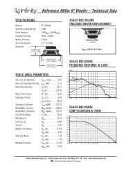
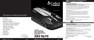
Left & Right<br />
Preamp Output Jacks<br />
Remote<br />
Level Port<br />
(pg. 8)<br />
Remote<br />
Level<br />
Port<br />
(pg. 8) Left & Right<br />
Preamp Input Jacks<br />
(pg. 6)<br />
Preamp<br />
Outputs<br />
LEFT<br />
RIGHT<br />
<strong>Amplifier</strong><br />
Inputs<br />
LEFT<br />
RIGHT<br />
Output Polarity<br />
Switch<br />
(pg. 7)<br />
Reversed | Normal<br />
Output Polarity<br />
installation aPPliCations<br />
This amplifier is designed for operation in<br />
vehicles with 12V, negative-ground electrical<br />
systems. Use of this product in vehicles with<br />
positive ground and/or voltages other than 12V<br />
may result in damage to the product and will void<br />
the warranty.<br />
This product is not certified or approved for<br />
use in aircraft.<br />
Do not attempt to “bridge” the outputs of this<br />
amplifier with the outputs of a second amplifier,<br />
including an identical one.<br />
Power/Protection<br />
Status Indicator<br />
(pg. 9)<br />
Power<br />
Made in China<br />
Input Sensitivity<br />
Control<br />
(pg. 6)<br />
15A<br />
Fuses<br />
(pg. 5)<br />
Filter<br />
Frequency Selector<br />
(pg. 7)<br />
Bass Boost<br />
Control<br />
(pg. 8)<br />
min max 40 130 O +12dB<br />
Input Sens. LP Filter Frequency (Hz) Bass Boost<br />
+12 V Power<br />
Connector<br />
(pg. 5)<br />
FUSES + 12VDC<br />
15A 15A 15A<br />
a JL Audio® Company<br />
Remote Turn-On<br />
Connector<br />
(pg. 6)<br />
Chassis Ground<br />
Connector<br />
(pg. 5)<br />
Remote Ground<br />
Planning Your installation<br />
It is important that you take the time to read<br />
this manual and that you plan out your<br />
installation carefully. The following are some<br />
considerations that you must take into account<br />
when planning your installation.<br />
Cooling efficiency Considerations:<br />
The outer shell of your TMA amplifier is designed<br />
to remove heat from the amplifier circuitry. For<br />
optimum cooling performance, this outer shell<br />
should be exposed to as large a volume of air<br />
as possible. Enclosing the amplifier in a small,<br />
poorly ventilated chamber can lead to excessive<br />
heat build-up and degraded performance. If an<br />
installation calls for an enclosure around the<br />
amplifier, we recommend that this enclosure<br />
be ventilated with the aid of a fan. In normal<br />
applications, fan-cooling is not necessary.<br />
Speaker Outputs<br />
(pg. 9)<br />
Speaker Output (Mono)<br />
Mounting the amplifier upside down is<br />
strongly discouraged.<br />
If mounting the amplifier under a seat,<br />
make sure there is at least 1 inch (2.5 cm) of<br />
space above the amplifier’s outer shell to permit<br />
proper cooling.<br />
safety Considerations:<br />
Your amplifier needs to be installed in a dry,<br />
well-ventilated environment and in a manner<br />
which does not interfere with your vehicle’s safety<br />
equipment (air bags, seat belt systems, ABS brake<br />
systems, etc.). You should also take the time to<br />
securely mount the amplifier using appropriate<br />
hardware so that it does not come loose in the<br />
event of a collision or a sudden jolt to the vehicle.<br />
stupid mistakes to avoid:<br />
• Check before drilling any holes in your vehicle<br />
to make sure that you will not be drilling<br />
through a gas tank, brake line, wiring harness or<br />
other vital vehicle system.<br />
• Do not run system wiring outside or underneath<br />
the vehicle. This is an extremely dangerous<br />
practice which can result in severe damage to<br />
your vehicle and person.<br />
• Protect all system wires from sharp metal<br />
edges and wear by carefully routing them,<br />
tying them down and using grommets and<br />
loom where appropriate.<br />
• Do not mount the amplifier in the engine<br />
compartment, under the vehicle, on the roof<br />
or in any other area that will expose the<br />
amplifier circuitry to the elements.<br />
2 Total Mobile Audio 3<br />
a JL Audio® Company
ProduCt desCriPtion<br />
The TMA T2-500.1 is a monoblock<br />
subwoofer amplifier utilizing Class B<br />
technology. Its frequency response is limited<br />
to the range below 125 Hz. It is not designed<br />
for driving midrange speakers or tweeters.<br />
It has been optimized for low-frequency<br />
amplification. For detailed specifications,<br />
please refer to Appendix B (page 13).<br />
tYPiCal installation sequenCe<br />
The following represents the sequence<br />
for a typical amplifier installation, using an<br />
aftermarket source unit or OEM Interface<br />
product. Additional steps and different<br />
procedures may be required in some applications.<br />
If you have any questions, please contact your<br />
authorized TMA dealer for assistance.<br />
1) Disconnect the negative battery post<br />
connection and secure the disconnected cable<br />
to prevent accidental re-connection during<br />
installation. This step is not optional!<br />
2) Run power wire (minimum 4 AWG)<br />
from the battery location to the amplifier<br />
mounting location, taking care to<br />
route it in such a way that it will not be<br />
damaged and will not interfere with<br />
vehicle operation. Use 2 AWG or 1/0<br />
AWG power wire if additional amplifiers<br />
are being installed with the T2-500.1.<br />
3) Connect power wire to the positive battery<br />
post. Fuse the wire with an appropriate fuse<br />
block (and connectors) within 18 inches (45<br />
cm) wire length of the positive battery post.<br />
This fuse is essential to protect the vehicle.<br />
Do not install the fuse until the power wire<br />
has been connected to the amplifier.<br />
4) Run signal cables (RCA cables) and remote<br />
turn-on wire from the source unit to the<br />
amplifier mounting location.<br />
5) Run speaker wire from the speaker systems<br />
to the amplifier mounting location.<br />
6) Find a good, solid metal grounding point<br />
close to the amplifier and connect the negative<br />
power wire to it using appropriate hardware.<br />
Use minimum 4 AWG power wire, no longer<br />
than 36 inches (90 cm) from the amplifier to<br />
the ground connection point. In some vehicles,<br />
it may be necessary to upgrade the battery<br />
ground wire. (See page 5 for important notice).<br />
7) Securely mount the amplifier using<br />
appropriate hardware.<br />
Made in China<br />
8) Connect the positive and negative power<br />
wires to the amplifier.<br />
9) Connect the remote turn-on wire<br />
to the amplifier.<br />
10) Connect the RCA input cables<br />
to the amplifier.<br />
11) Connect the speaker wires to the amplifier.<br />
12) Carefully review the amplifier’s control<br />
settings to make sure that they are set according<br />
to the needs of the system.<br />
13) Install power wire fuse (60A for a single T2-500.1)<br />
and reconnect the negative battery post terminal.<br />
14) Turn on the source unit at a low level<br />
to double-check that the amplifier is configured<br />
correctly. Resist the temptation to crank it up<br />
until you have verified the control settings.<br />
15) Make necessary adjustments to the input<br />
sensitivity controls to obtain the right<br />
overall output and the desired balance<br />
in the system. See Appendix A (page 12)<br />
for the recommended input sensitivity<br />
setting method.<br />
16) Enjoy the fruits of your labor with your<br />
favorite music.<br />
15A<br />
Power ConneCtions<br />
Before installing the amplifier, disconnect the<br />
negative (ground) wire from the vehicle’s battery.<br />
This will prevent accidental damage to the system,<br />
the vehicle and your person during installation.<br />
FUSES + 12VDC<br />
15A 15A 15A<br />
Speaker Output (Mono)<br />
4 Total Mobile Audio 5<br />
Remote Ground<br />
The T2-500.1’s “+12 VDC” (positive) and<br />
“Ground” (ground) connections are designed to<br />
accept 4 AWG power wire. 4 AWG is a minimum<br />
power wire size for this amplifier.<br />
If you are installing the T2-500.1 with other<br />
amplifiers and wish to use a single main power<br />
wire, use 2 AWG or 1/0 AWG main power wire<br />
(depending on the overall current demands of<br />
all the amplifiers in the system). This 2 AWG<br />
or 1/0 AWG power wire should terminate into<br />
a distribution block mounted as close to the<br />
amplifiers as possible and should connect to the<br />
T2-500.1 with 4 AWG power wire.<br />
Note: that smaller AWG numbers mean bigger<br />
wire and vice-versa (1/0 AWG is the largest,<br />
2 AWG is smaller, then 4 AWG, then<br />
8 AWG, etc.).<br />
To connect the power and ground wires to the<br />
amplifier, strip 1/2-inch (12 mm) of insulation<br />
from each wire and insert the bare wire into the<br />
the appropriate terminal block positions on the<br />
T2-500.1. Use a Phillips screwdriver to secure the<br />
wire via the screw on the top of each terminal.<br />
The “Ground” connection should be made<br />
using 4 AWG wire and should be kept as short<br />
as possible, while accessing a solid piece of sheet<br />
metal in the vehicle. The surface of the sheet<br />
metal should be sanded at the contact point<br />
to create a clean, metal-to-metal connection<br />
between the chassis and the termination of<br />
the ground wire. The use of a star washer to<br />
lock down the connection is advisable.<br />
Made in China<br />
Any wires run through metal barriers (such as<br />
firewalls), must be protected with a high quality<br />
insulating grommet to prevent damage to the<br />
insulation of the wire. Failure to do so may result<br />
in a dangerous short circuit.<br />
Many vehicles employ small (10 AWG -<br />
6 AWG) wire to ground the battery to the<br />
vehicle chassis and to connect the alternator’s<br />
positive connection a JL Audio® Company to the battery. To prevent<br />
voltage drops, these wires should be upgraded<br />
to 4 AWG (or larger) when installing a<br />
T2-500.1.<br />
Fuse requirements<br />
While the T2-500.1 has four 15A ATC fuses<br />
on its power connection panel, these do nothing<br />
to protect the vehicle from a dangerous short<br />
circuit in the power wire. They only protect the<br />
amplifier. It is absolutely vital that the main<br />
power lead to the amplifier(s) in the system be<br />
fused within 18 inches (45 cm) of the positive<br />
battery post connection. The fuse value at each<br />
power wire should be high enough for all of the<br />
equipment being run from that power wire.<br />
If only the T2-500.1 is being run from that power<br />
wire, we recommend a 60A fuse be used. AFS or<br />
MAXI-type fuses are recommended.<br />
15A<br />
FUSES + 12VDC<br />
15A 15A 15A
“remote” turn-on<br />
The T2-500.1 is turned on and off<br />
using a conventional +12V remote turnon<br />
lead, typically controlled by the<br />
source unit’s remote turn-on output.<br />
15A<br />
+ 12VDC<br />
Remote Ground<br />
The amplifier will turn on when +12V is<br />
present at its “Remote” input and turn off when<br />
+12V is switched off. If a source unit does not<br />
have a dedicated remote turn-on output, the<br />
amplifier’s turn-on lead can be connected to +12V<br />
via a switch that derives power from an ignitionswitched<br />
circuit.<br />
18 AWG wire is more than adequate for<br />
the remote turn-on connection. To connect<br />
the remote turn-on wire to the amplifier, strip<br />
1/2-inch (12 mm) of insulation from the wire<br />
and insert it into the “Remote” receptacle on the<br />
power connector. Tighten the connector down<br />
using a Phillips screwdriver.<br />
“amPliFier inPuts”<br />
The T2-500.1 only offers low-level (preamp<br />
level) input connections via a single pair of RCAtype<br />
jacks that are compatible with a wide range<br />
of aftermarket source units and processors. If you<br />
wish to use speaker level signals, you will need to<br />
employ a line-output converter (not included).<br />
Speaker Output (Mono)<br />
Remote<br />
Level<br />
Port<br />
Preamp<br />
Outputs<br />
LEFT<br />
RIGHT<br />
Remote<br />
<strong>Amplifier</strong> Level<br />
Inputs<br />
Port<br />
LEFT<br />
RIGHT<br />
Preamp<br />
Outputs<br />
LEFT<br />
Reversed | Normal<br />
Output Polarity<br />
a JL Audio® Company<br />
RIGHT<br />
<strong>Amplifier</strong><br />
Inputs<br />
LEFT<br />
Power<br />
You may run a stereo or a mono signal into<br />
the inputs of the amplifier. The amplifier’s input<br />
section automatically sums stereo signals to mono<br />
for the internal amplifier section.<br />
The amplifier will operate with only one<br />
input connection (left or right), but will require<br />
an increase in input sensitivity to overcome the<br />
loss of signal. If a mono input signal is to be run<br />
into the RCA jacks, we recommend that you use<br />
a “Y-adaptor” to split the mono signal into both<br />
the Left and Right inputs of the amplifier.<br />
If you plan to use the preamp outputs to feed a<br />
stereo amplifier, you must connect a stereo<br />
signal to the input of the amplifier. A mono<br />
signal into the amplifier will result in a mono<br />
signal out of the preamp output.<br />
RIGHT<br />
Reversed | Normal<br />
Output Polarity<br />
“inPut sensitiVitY” (gain) adJustment<br />
Located next to the input connectors is a rotary<br />
control labeled “Input Sens.”. This rotary control<br />
can be used to match the source unit’s output<br />
voltage to the input stage of the amplifier for<br />
maximum clean output.<br />
min max 40 130 O +12dB<br />
Input Sens. LP Filter Frequency (Hz) Bass Boost<br />
Preamp <strong>Amplifier</strong><br />
min max Outputs40<br />
130 Inputs O +12dB<br />
Remote<br />
Input Level Sens. LP LEFT Filter Frequency LEFT (Hz) Bass Boost<br />
Port<br />
6 Total Mobile Audio 7<br />
Power<br />
Reversed | Normal<br />
Output Polarity<br />
Rotating the control clockwise will result<br />
in higher sensitivity (louder for a given input<br />
voltage). Rotating the control counter-clockwise<br />
RIGHT RIGHT<br />
will result in lower sensitivity (quieter for a given<br />
input voltage). To properly set the amplifier for<br />
maximum clean output, please refer to Appendix<br />
A (page 12) in this manual. After using this<br />
procedure, you can then adjust the level of the<br />
amplifier by adjusting the input sensitivity<br />
downward, if the amplifier requires attenuation to<br />
achieve the desired system balance.<br />
Do not increase the “Input Sens.” setting for<br />
any amplifier in the system beyond the maximum<br />
level established during the procedure outlined<br />
in Appendix A (page 12). Doing so will result in<br />
audible distortion and possible speaker damage.<br />
Power a JL Audio® Company<br />
Remote<br />
Level<br />
Port<br />
“lP Filter” (CrossoVer) Control<br />
The T2-500.1 employs a 12dB/octave low-pass<br />
(LP) active filter for its internal channel. This<br />
feature is designed to attenuate frequencies above<br />
its filter frequency, so that the system’s subwoofers<br />
do not reproduce any audible midrange content.<br />
The low-pass filter in the T2-500.1 is fully<br />
variable between 40 Hz and 130 Hz via the “LP<br />
Filter Frequency” control knob. The 12 o’clock<br />
position corresponds to 80 Hz, and is a good<br />
starting point for system tuning.<br />
a JL Audio® Company<br />
min max 40 130 O +12dB<br />
Input Sens. LP Filter Frequency (Hz) Bass Boost<br />
“outPut PolaritY” Control<br />
The T2-500.1 includes a switch to quickly reverse<br />
the polarity of its audio output. This is very useful<br />
for establishing a smooth transition between the<br />
subwoofers and main speaker systems. Choose<br />
the position that results in the strongest midbass<br />
and the best “up-front” bass presence.<br />
Preamp<br />
Outputs<br />
LEFT<br />
RIGHT<br />
<strong>Amplifier</strong><br />
Inputs<br />
LEFT<br />
RIGHT<br />
Reversed | Normal<br />
Output Polarity<br />
Power<br />
min max<br />
Input Sens.<br />
a
“PreamP outPuts”<br />
The T2-500.1 incorporates a preamp output<br />
section, designed to make multiple amplifier<br />
systems easy to set up. This section consists<br />
of a pair of RCA-type jacks marked<br />
“Preamp Outputs”.<br />
Remote<br />
Level<br />
Port<br />
Preamp<br />
Outputs<br />
LEFT<br />
RIGHT<br />
<strong>Amplifier</strong><br />
Inputs<br />
LEFT<br />
Made in China<br />
RIGHT<br />
15A<br />
Reversed | Normal<br />
Output Polarity<br />
The Preamp outputs deliver the same signal that<br />
is being fed to the inputs. (If the input signal are<br />
full-range, the preamp outputs will be full-range).<br />
This signal is not affected by the bass boost or LP<br />
FIlter processing selected for the amplifier.<br />
“bass boost” Control<br />
The T2-500.1 includes a single band, boostonly<br />
bass equalizer controlled by a rotary knob<br />
marked “Bass Boost”. This control has a boost<br />
range of 0dB (full-counterclockwise) to +12dB<br />
(full-clockwise) and is centered at 45 Hz.<br />
max 40 130 O +12dB<br />
ens. LP Filter Frequency (Hz) Bass Boost<br />
a JL Audio® Company<br />
remote leVel Control<br />
The T2-500.1 includes a remote level control<br />
that can be mounted in the front of the vehicle.<br />
This control allows the owner to adjust the overall<br />
subwoofer level to taste. To connect the remote<br />
bass control knob, insert its plug into the jack<br />
labeled “Remote Level Port” on the amplifier<br />
and route the cable and control to the desired<br />
location in the front of the vehicle.<br />
FUSES + 12VDC<br />
15A 15A 15A<br />
Power<br />
Remote Ground<br />
Preamp <strong>Amplifier</strong><br />
Outputs Inputs<br />
Remote<br />
min max Level<br />
LEFT 40 130 LEFT O +12dB<br />
Port<br />
Input Sens. LP Filter Frequency (Hz) Bass Boost<br />
RIGHT<br />
RIGHT<br />
Care should be taken to securely mount this<br />
control in a manner that does not interfere with<br />
vehicle operation.<br />
When setting the amplifier’s input sensitivity,<br />
the Remote Level Control should be unplugged or<br />
at full clockwise rotation (maximum level).<br />
Reversed | Normal<br />
Output Polarity<br />
sPeaKer outPut<br />
Speaker connection to the T2-500.1 is<br />
straightforward and takes place at the far right<br />
of the power/speaker connection panel. A<br />
single positive (“+”) connection and a single<br />
negative (“–”) connection are available via a<br />
connector labeled “Speaker Output (Mono)”.<br />
Speaker Output (Mono)<br />
a JL Audio® Company<br />
a JL Audio® Company<br />
min max 40 130 O +12dB<br />
Input Sens. LP Filter Frequency (Hz) Bass Boost<br />
Speaker loads below 2Ω nominal are not<br />
recommended and will cause the amplifier to<br />
enter into a protection mode.<br />
Do not chassis ground any speakers connected<br />
RIGHT<br />
to this or any other TMA amplifier. Doing so will<br />
cause the amplifier to go into protection.<br />
To connect the speaker wires to the amplifier,<br />
strip 1/2-inch (12 mm) of insulation from<br />
each speaker wire and insert them into their<br />
appropriate connector (observing correct<br />
polarity). Then, tighten each connector using a<br />
Phillips screwdriver.<br />
Do NOT attempt to “bridge” two T2-500.1’s<br />
together or combine their output to a single<br />
load in any manner. Doing so will damage the<br />
amplifier(s).<br />
Before reconnecting the battery ground and<br />
turning the system on, verify that all control<br />
settings on the amplifier are set according to<br />
the needs of the system.<br />
“Power” indiCator led /<br />
ProteCtion CirCuitrY<br />
The multi-color “Power” LED on the T2-500.1<br />
also serves as a status indicator for certain fault<br />
conditions. Its operation is as follows:<br />
1) Red: Amplifer is turning on.<br />
2) Green: <strong>Amplifier</strong> is on / operating normally.<br />
3) Yellow: Protection mode activated due to one<br />
of the following: Shorted outputs, too low of a<br />
load impedance or thermal overload (too hot).<br />
Once the fault condition is corrected, the<br />
amplifier will return to normal operating<br />
mode and the LED will turn green again. For<br />
information on troubleshooting this amplifier,<br />
refer to Appendix C (pages 14, 15).<br />
Reversed | Normal<br />
Output Polarity<br />
min max 40 1<br />
8 Total Mobile Audio 9<br />
Power<br />
Remote<br />
Level<br />
Port<br />
Preamp<br />
Outputs<br />
LEFT<br />
<strong>Amplifier</strong><br />
Inputs<br />
LEFT<br />
RIGHT<br />
a JL Audio® Company<br />
Power<br />
Input Sens.<br />
serViCing Your tma amPliFier<br />
If your amplifier fails or malfunctions, please<br />
return it to your authorized TMA dealer so that<br />
it may be sent in to TMA for service. There are<br />
no user serviceable parts or fuses inside the<br />
amplifier. The unique nature of the circuitry in<br />
the TMA amplifiers requires specifically trained<br />
service personnel. Do not attempt to service the<br />
amplifier yourself or through unauthorized repair<br />
facilities. This will not only void the warranty,<br />
but may result in the creation of more problems<br />
within the amplifier.<br />
If you have any questions about the installation<br />
or setup of the amplifier not covered in this<br />
manual, please contact your dealer or technical<br />
support.<br />
tma technical support:<br />
(954) 443-1100<br />
9:00 AM – 5:30 PM (Eastern Time Zone)<br />
Monday - Friday<br />
LP Filter Frequ
aPPendix a:<br />
input sensitivity level setting<br />
Following the directions below will allow the<br />
installer to adjust the input sensitivity of each<br />
amplifier channel pair simply and easily in just a<br />
few minutes using equipment which is commonly<br />
available in installation bays.<br />
necessary equipment<br />
• Digital AC Voltmeter<br />
• CD with a sine-wave test tone recorded at<br />
0 dB reference level in the frequency range<br />
to be amplified for that set of channels<br />
(50 Hz for subwoofer channels, 1 kHz for a<br />
midrange application). Do not use attenuated<br />
test tones (-10 dB, -20 dB, etc.).<br />
the nine-step Procedure<br />
1) Disconnect the speaker(s) from the<br />
amplifier’s speaker output connectors.<br />
2) Turn off all processing (bass/treble, loudness,<br />
EQ, etc.) on the source unit, processors (if used)<br />
and amplifier. Set fader control to center position<br />
and subwoofer level control to 3/4 of maximum.<br />
If connected, set the amplifier’s Remote Bass<br />
Control at maximum (full clockwise).<br />
3) Turn the “Input Sens.” control all the<br />
way down.<br />
4) Set the source unit volume to 3/4 of full<br />
volume. This will allow for reasonable gain<br />
overlap with moderate clipping at full volume.<br />
5) Using the chart on this page, determine the target<br />
voltage for input sensitivity adjustment according<br />
to the nominal impedance of the speaker system<br />
connected to the amplifier outputs.<br />
6) Verify that you have disconnected the speakers<br />
before proceeding. Play a track with an<br />
appropriate sine wave (within the frequency<br />
range to be amplified) at 3/4 source unit volume.<br />
7) Connect the AC voltmeter to the speaker output<br />
connectors of the amplifier. Make sure you test<br />
the voltage at the correct connectors (+ and –).<br />
8) Increase the “Input Sens.” control until the<br />
target voltage is observed with the voltmeter.<br />
9) Once you have adjusted the amplifier to<br />
its maximum low-distortion output level,<br />
reconnect the speaker(s). The “Input Sens.”<br />
controls can now be adjusted downward if the<br />
amplifier requires attenuation to achieve the<br />
desired system balance.<br />
Do not increase any “Input Sens.” setting for<br />
any amplifier channel or channel pair in the<br />
system beyond the maximum level established<br />
during this procedure. Doing so will result in<br />
audible distortion and possible speaker damage.<br />
It will be necessary to re-adjust the<br />
“Input Sens.” for the affected channels if any<br />
equalizer boost is activated after setting the<br />
“Input Sens.” with this procedure. This applies<br />
to any EQ boost circuit, including source unit<br />
tone controls or EQ circuits. EQ cuts will not<br />
require re-adjustment.<br />
nom. impedance target aC Voltage<br />
4Ω 37 V<br />
3Ω 35.5 V<br />
2Ω 31.5 V<br />
aPPendix b:<br />
t2-500.1 specifications<br />
general specifications:<br />
Recommended Fuse Value: 60A<br />
Recommended Fuse Type: ANL at battery, 4x 15A ATC<br />
fuses on amplifier chassis.<br />
input section:<br />
Low-Level Input: Single-ended with RCA jacks<br />
Low-Level Input Range: 200mV - 4V RMS<br />
amplifier section:<br />
<strong>Amplifier</strong> Topology: Class B Monaural with<br />
complementary bi-polar outputs<br />
Power Supply: PWM switching type, unregulated<br />
Rated Power with less than 1% THD (14.4V supply):<br />
340W RMS x 1 @ 4Ω<br />
420W RMS x 1 @ 3Ω<br />
<strong>500W</strong> RMS x 1 @ 2Ω<br />
Frequency Response: 10 - 100 Hz (+/– 1 dB)<br />
Crossover section:<br />
Low-Pass Filter: 12 dB/octave with continuously variable<br />
cutoff frequency selection from 40 - 130 Hz. Non-defeatable.<br />
Preamp outputs:<br />
2-Channel, pass-through with unity gain, RCA-type jacks.<br />
bass boost:<br />
Single-band with 45 Hz center frequency, adjustable from<br />
10 Total Mobile Audio 11<br />
0 to +12dB.<br />
remote level Control:<br />
Via included, wired remote control knob. Full mute to<br />
0 dB range.<br />
dimensions (lxwxH):<br />
13.20" x 9.60" x 2.15" (335 mm x 244 mm x 55 mm)<br />
Due to ongoing product development, all specifications are subject to<br />
change without notice.
aPPendix C: troublesHooting<br />
“How do i properly set the input sensitivity on my amplifier”<br />
Please refer to Appendix A (page 12) to set the input sensitivity for<br />
maximum, low-distortion output.<br />
“my amplifier doesn’t turn on”<br />
Check the fuse, not just visually, but with a continuity meter. It is<br />
possible for a fuse to have poor internal connections that<br />
cannot be found by visual inspection. It is best to take the<br />
fuse out of the holder for testing. If no problem is found with<br />
the fuse, inspect the fuse-holder.<br />
Check the integrity of the connections made to each of the<br />
“+12VDC”, “Ground”, and “Remote” terminals. Ensure<br />
that no wire insulation is pinched by the terminal set screw<br />
and that each connection is tight.<br />
Check to make sure there is +12V at the “Remote” connection of the<br />
amplifier. In some cases, the turn-on lead from the source unit<br />
is insufficient to turn on multiple devices and the use of a relay<br />
is required. To test for this problem, jump the “+12VDC” wire<br />
to the “Remote” terminal to see if the amplifier turns on. If this<br />
does not work, proceed to the next step.<br />
“my amplifier’s output fluctuates when i tap on it or hit a bump”<br />
Check the connections to the amplifier. Make sure that the<br />
insulation for all wires has been stripped back far enough to<br />
allow a good contact area inside the terminal block.<br />
Check the input connectors to ensure that they all are making good<br />
contact with the input jacks on the amplifier.<br />
“my amplifier turns on, but there is no output”<br />
Check the input signal using an AC voltmeter to measure the<br />
voltage from the source unit while an appropriate test tone is<br />
played through the source unit (disconnect the input cables<br />
from the amplifier prior to this test). The frequency used<br />
should be in the range that is to be amplified by the amplifier<br />
(example: 50 Hz for a sub bass application or 1 kHz for a full<br />
range / high-pass application). A steady, sufficient voltage<br />
(between 0.2 and 8.0-volts) should be present at the output of<br />
the signal cables.<br />
Check the output of the amplifier. Using the procedure explained in<br />
the previous check item (after plugging the input cables back<br />
into the amplifier) test for output at the speaker outputs of<br />
the amplifier. Unless you enjoy test tones at high levels, it is<br />
a good idea to remove the speaker wires from the amplifier<br />
while doing this. Turn the volume up approximately half<br />
way. 5V or more should be measured at the speaker outputs.<br />
This output level can vary greatly between amplifiers but it<br />
should not be in the millivolt range with the source unit at<br />
half volume. If you are reading sufficient voltage, check your<br />
speaker connections as explained below.<br />
Check to ensure that the speaker wires are making a good<br />
connection with the metal inside the terminal block. The<br />
speaker wire connectors are designed to accept up to 8 AWG<br />
wire. Make sure to strip the wire to allow for a sufficient<br />
connection with the metal inside the terminal block.<br />
12 Total Mobile Audio 13
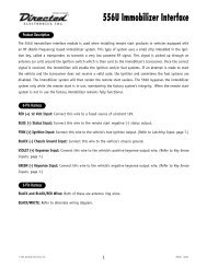
installation notes:<br />
Use this diagram to document your amplifier’s switch and control positions.<br />
Remote<br />
Level<br />
Port<br />
Preamp<br />
Outputs<br />
LEFT<br />
RIGHT<br />
<strong>Amplifier</strong><br />
Inputs<br />
LEFT<br />
RIGHT<br />
Reversed | Normal<br />
Output Polarity<br />
Power<br />
min max 40 130 O +12dB<br />
Input Sens. LP Filter Frequency (Hz) Bass Boost<br />
a JL Audio® Company<br />
14 Total Mobile Audio 15
limited warrantY - amPliFiers (usa)<br />
TOTAL MOBILE AUDIO (TMA) warrants this product to be free of defects in materials and<br />
workmanship for a period of one (1) year from the original date of purchase.<br />
This warranty is not transferrable and applies only to the original purchaser from an authorized<br />
TMA dealer. Should service be necessary under this warranty for any reason due to manufacturing<br />
defect or malfunction, TMA will (at its discretion), repair or replace the defective product with new or<br />
remanufactured product at no charge. Damage caused by the following is not covered under warranty:<br />
accident, misuse, abuse, product modification or neglect, failure to follow installation instructions,<br />
unauthorized repair attempts, misrepresentations by the seller. This warranty does not cover incidental<br />
or consequential damages and does not cover the cost of removing or reinstalling the unit(s). Cosmetic<br />
damage due to accident or normal wear and tear is not covered under warranty.<br />
warranty is void if the product’s serial number has been removed or defaced.<br />
Any applicable implied warranties are limited in duration to the period of the express warranty as<br />
provided herein beginning with the date of the original purchase at retail, and no warranties, whether<br />
express or implied, shall apply to this product thereafter. Some states do not allow limitations on implied<br />
warranties, therefore these exclusions may not apply to you. This warranty gives you specific legal rights,<br />
and you may also have other rights which vary from state to state.<br />
if you need service on your Jl audio product:<br />
All warranty returns should be sent to TMA ’s <strong>Amplifier</strong> Service Facility freight-prepaid through<br />
an authorized TMA dealer and must be accompanied by proof of purchase (a copy of the original sales<br />
receipt). Direct returns from consumers or non-authorized dealers will be refused unless specifically<br />
authorized by TMA with a valid return authorization number.<br />
Warranty expiration on products returned without proof of purchase will be determined from the<br />
manufacturing date code. Coverage may be invalidated as this date is previous to purchase date. Nondefective<br />
items received will be returned freight-collect. Customer is responsible for shipping charges and<br />
insurance in sending the product to TMA. Freight damage on returns is not covered under warranty.<br />
For service information in the u.s.a. please call<br />
tma / Jl audio Customer service: (954) 443-1100<br />
9:00 AM – 5:30 PM (Eastern Time Zone)<br />
total mobile audio / Jl audio, inc<br />
10369 North Commerce Pkwy.<br />
Miramar, FL 33025<br />
(do not send product for repair to this address)<br />
international warranties:<br />
Products purchased outside the United States of America are covered only<br />
by that country’s distributor and not by Total Mobile Audio / JL Audio, Inc.<br />
Printed in China T2500_1-CH-05-2008