Theoretical and Experimental Modelling of Particulate Flows
Theoretical and Experimental Modelling of Particulate Flows
Theoretical and Experimental Modelling of Particulate Flows

You also want an ePaper? Increase the reach of your titles
YUMPU automatically turns print PDFs into web optimized ePapers that Google loves.
Lecture Series 2000-06<br />
<strong>Theoretical</strong> <strong>and</strong> <strong>Experimental</strong> <strong>Modelling</strong> <strong>of</strong><br />
<strong>Particulate</strong> <strong>Flows</strong><br />
April 3 – 7, 2000<br />
von Karman Institute for Fluid Dynamics<br />
Overview <strong>and</strong> Fundamentals<br />
Part I <strong>and</strong> II<br />
Pr<strong>of</strong>. Dr.-Ing. M. Sommerfeld<br />
Institut für Verfahrenstechnik<br />
Fachbereich Ingenieurwissenschaften<br />
Martin-Luther-Universität Halle-Wittenberg<br />
D-06099 Halle (Saale), Germany
Summary<br />
The lecture summarises the fundamentals <strong>of</strong> fluid-particle flows <strong>and</strong> important physical<br />
phenomena influencing the particle motion, such as wall collisions <strong>and</strong> inter-particle<br />
collisions. The first part introduces a classification <strong>of</strong> multiphase flows <strong>and</strong> dispersed particle-<br />
laden flows <strong>and</strong> provides the definitions for describing the content <strong>of</strong> the dispersed phase. In<br />
the second chapter some problems <strong>of</strong> engineering relevance are introduced, in order to<br />
emphasise the importance <strong>of</strong> a detailed description <strong>of</strong> particle motion in turbulent flows. The<br />
equations to calculate the motion <strong>of</strong> particles are introduced in part three, including a<br />
summary <strong>of</strong> all relevant forces acting on particles. Recent results on transverse lift forces due<br />
to shear <strong>and</strong> particle rotation are also introduced. Finally, the importance <strong>of</strong> the different<br />
forces, e.g. added mass, Basset force, <strong>and</strong> pressure force, for calculating the particle motion in<br />
an oscillatory flow field is discussed.<br />
Part four introduces the fundamentals for calculating the collision <strong>of</strong> spherical particles with<br />
walls <strong>and</strong> the importance <strong>of</strong> wall roughness for this process. Bases on Lagrangian calculations<br />
<strong>of</strong> the particles in channel <strong>and</strong> pipe flows, the importance <strong>of</strong> wall collisions <strong>and</strong> wall<br />
roughness for the particle behaviour is emphasised. Moreover, it is pointed out, that the<br />
modelling <strong>of</strong> wall collisions is essential for predicting the correct pressure loss in pneumatic<br />
conveying.<br />
The fifth part is devoted to inter-particle collisions. After an introduction <strong>of</strong> the different<br />
collision mechanisms in laminar <strong>and</strong> turbulent flows, the basic equations for calculating inter-<br />
particle collisions in a Lagrangian frame are introduced. The importance <strong>of</strong> inter-particle<br />
collisions is demonstrated on the basis <strong>of</strong> Lagrangian calculations <strong>of</strong> a particle-laden<br />
horizontal channel flow. It is shown that whenever inhomogenities <strong>of</strong> the particle<br />
concentration develop in a flow, inter-particle collisions become <strong>of</strong> great importance already<br />
for quite low overall particle concentration.<br />
The final chapter gives a brief introduction <strong>of</strong> the numerical methods being applied for the<br />
calculation <strong>of</strong> dispersed particle-laden flows.<br />
2
Content<br />
1. Classification <strong>of</strong> Multiphase flows 4<br />
2. Examples <strong>of</strong> Engineering Practice 7<br />
3. Particle Motion in Fluids 10<br />
3.1 Drag Force 11<br />
3.2 Pressure Gradient <strong>and</strong> Buoyancy Force 17<br />
3.3 Added Mass <strong>and</strong> Basset Force 18<br />
3.4 Body Forces 19<br />
3.5 Slip-Shear Lift Force 20<br />
3.6 Slip-Rotation Lift Force 22<br />
3.7 Torque 24<br />
3.8 Response Time <strong>and</strong> Stokes Number 25<br />
3.9 Importance <strong>of</strong> the Different Forces 26<br />
4. Particle-Wall Collisions 29<br />
4.1 Velocity Change During Wall Collisions 29<br />
4.2 Wall Roughness Effects 31<br />
4.3 Importance <strong>of</strong> Wall Collisions in Channel <strong>and</strong> Pipe <strong>Flows</strong> 34<br />
5. Inter-Particle Collisions 39<br />
5.1 Importance <strong>of</strong> Inter-Particle Collisions 41<br />
5.2 Particle Velocity Change due to Inter-Particle Collisions 44<br />
5.3. Inter-particle Collision Effects in Turbulent <strong>Flows</strong> 48<br />
6. Methods for the Prediction <strong>of</strong> Multiphase <strong>Flows</strong> 54<br />
7. Nomenclature 57<br />
8. References 59<br />
3
1. Classification <strong>of</strong> Multiphase flows<br />
Multiphase flows may be encountered in various forms in industrial practice (Figure 1), as for<br />
example, transient flows with a transition from pure liquid to a vapour flow as a result <strong>of</strong><br />
external heating, separated flows (i.e. stratified flows, slug flows, or film flows), <strong>and</strong><br />
dispersed two-phase flows where one phase is present in the form <strong>of</strong> particles, droplets, or<br />
bubbles in a continuous carrier phase (i.e. gas or liquid). Such dispersed two-phase flows,<br />
which are the main concern <strong>of</strong> the present contribution, are encountered in numerous<br />
technical <strong>and</strong> industrial processes, as for example in particle technology, chemical<br />
engineering, <strong>and</strong> biotechnology. Dispersed two-phase flows may be classified in terms <strong>of</strong> the<br />
different phases being present as summarised in Table 1 together with some <strong>of</strong> the most<br />
important industrial processes.<br />
Additionally, numerous processes may involve more than two phases (i.e. multiphase flows),<br />
as for example in a spray scrubber where droplets <strong>and</strong> solid particles are dispersed in a gas<br />
flow <strong>and</strong> the aim is to collect the particles by the droplets.<br />
a)<br />
b)<br />
c)<br />
Liquid<br />
Liquid<br />
Gas<br />
Liquid<br />
Gas Bubbles<br />
Gas bubbles<br />
4<br />
Gas<br />
Liquid Droplets<br />
Liquid<br />
Gas<br />
Gas<br />
Liquid Droplets or Solid Particles<br />
Figure 1.1: Different regimes <strong>of</strong> two-phase flows, a) transient two-phase flow, b) separated<br />
two-phase flow, c) dispersed two-phase flow
Continuous/Dispersed<br />
Phase<br />
Industrial/Technical Application<br />
Gas-solid flows pneumatic conveying, particle separation in cyclones <strong>and</strong><br />
filters, fluidised beds<br />
Liquid-solid flows hydraulic conveying, liquid-solid separation, particle<br />
dispersion in stirred vessels<br />
Gas-droplet flows spray drying, spray cooling, spray painting, spray scrubbers<br />
Liquid-droplet flows mixing <strong>of</strong> immiscible liquids, liquid-liquid extraction<br />
Liquid-gas flows bubble columns, aeration <strong>of</strong> swage water, flotation<br />
Table 1.1: Summary <strong>of</strong> two-phase flow systems <strong>and</strong> important industrial <strong>and</strong> technical<br />
processes.<br />
For the characterisation <strong>of</strong> dispersed two-phase flows different properties are used, which are<br />
briefly summarised below. The volume fraction <strong>of</strong> the dispersed phase is the volume occupied<br />
by the particles in a unit volume. Hence this property is given by:<br />
∑<br />
N i VPi<br />
α P =<br />
i<br />
V<br />
(1.1)<br />
where Ni is the number <strong>of</strong> particles in the size fraction i, having the particle volume Vpi = π/6<br />
Dpi. The particle diameter Dpi in this context is the volume equivalent diameter <strong>of</strong> a sphere.<br />
Since the sum <strong>of</strong> the volume fraction <strong>of</strong> the dispersed phase <strong>and</strong> the continuous phase is unity,<br />
the continuous volume fraction is:<br />
( − )<br />
α F = 1 α P<br />
(1.2)<br />
The bulk density or concentration <strong>of</strong> the dispersed phase is the mass <strong>of</strong> particles per unit<br />
volume <strong>and</strong> hence given by:<br />
ρ (1.3)<br />
b<br />
P = c P = α P ρP<br />
Correspondingly, the bulk density <strong>of</strong> the continuous phase is:<br />
( − α P ) F<br />
b<br />
ρ =<br />
(1.4)<br />
F 1 ρ<br />
The sum <strong>of</strong> both bulk densities is called mixture density:<br />
( − α P ) ρF<br />
+ α P P<br />
ρ (1.5)<br />
b b<br />
m = ρF<br />
+ ρP<br />
= 1 ρ<br />
Often the particle concentration is also expressed by the number <strong>of</strong> particles per unit volume,<br />
as for example in clean-room technology:<br />
n<br />
P<br />
N P<br />
= (1.6)<br />
V<br />
5
Especially in gas-solid flows the mass loading is frequently used, which is defined as the mass<br />
flux <strong>of</strong> the dispersed phase to that <strong>of</strong> the fluid:<br />
α<br />
ρ<br />
P P P<br />
η =<br />
(1.7)<br />
( 1−<br />
α P ) ρF<br />
U F<br />
The proximity <strong>of</strong> particles in a two-phase flow system may be estimated from the inter-<br />
particle spacing, which however can be only determined for regular arrangements <strong>of</strong> the<br />
particles. For a cubic arrangement the inter-particle spacing, i.e. the distance between the<br />
centres <strong>of</strong> particles, is obtained from:<br />
L<br />
D<br />
P<br />
6<br />
U<br />
1/<br />
3<br />
⎛ π ⎞<br />
= ⎜<br />
6 ⎟<br />
(1.8)<br />
⎝ α P ⎠<br />
For a volume fraction <strong>of</strong> 1 % the spacing is 3.74 diameters <strong>and</strong> for 10 % only 1.74. Hence, for<br />
such high volume fractions the particles cannot be treated to move isolated, since fluid<br />
dynamic interactions become <strong>of</strong> importance. In many practical fluid-particle systems<br />
however, the particle volume fraction is much lower. Consider for example a gas-solid flow<br />
(particle density ρp = 2500 kg/m 3 , gas density <strong>of</strong> ρF = 1.18 kg/m 3 ) with a mass loading <strong>of</strong> one<br />
<strong>and</strong> assume no slip between the phases, then the volume fraction is about 0.05 % (i.e. αp = 5 ⋅<br />
10 -4 ). This results in an inter-particle spacing <strong>of</strong> about 10 particle diameters, hence, under<br />
such a condition a fluid dynamic interaction may be neglected.<br />
One-Way<br />
Coupling<br />
1 0 0<br />
i n t e r - p a r t i c l e s p a c i n g L / D P<br />
1 0 1<br />
Dilute Dispersed<br />
Two-Phase Flow<br />
Two-Way<br />
Coupling<br />
1 E - 8 1 E - 7 1 E - 6 1 E - 5 1 E - 4 1 E - 3 0 . 0 1 0 . 1<br />
v o l u m e f r a c t i o n [ - ]<br />
Dense Dispersed<br />
Two-Phase Flow<br />
Four-Way<br />
Coupling<br />
Figure 1.2 Regimes <strong>of</strong> dispersed two-phase flows as a function <strong>of</strong> particle volume fraction
A classification <strong>of</strong> dispersed two-phase flows with regard to the importance <strong>of</strong> interaction<br />
mechanisms was provided by Elghobashi (1994). Generally it is separated between dilute <strong>and</strong><br />
dense two-phase flows (Figure 1.2). A two-phase system may be regarded as dilute for<br />
volume fractions up to αp = 10 -3 (i.e. L/Dp ≈ 8). In this regime the influence <strong>of</strong> the particle<br />
phase on the fluid flow may be neglected for αp < 10 -6 (i.e. L/Dp ≈ 80). For higher volume<br />
fractions the influence <strong>of</strong> the particles on the fluid flow, which is <strong>of</strong>ten referred to as two-way<br />
coupling, needs to be accounted for. In the dense regime (i.e. for αp > 10 -3 ) additionally inter-<br />
particle interactions (i.e. collisions <strong>and</strong> fluid dynamic interactions between particles) become<br />
<strong>of</strong> importance. Hence, this regime is characterised by the so-called four-way coupling.<br />
Another interpretation for the separation between dilute <strong>and</strong> dense two-phase flow, which also<br />
accounts for particle inertia, will be introduced in the chapter „inter-particle collisions“.<br />
2. Examples <strong>of</strong> Engineering Practice<br />
The classical engineering approach for designing dispersed two-phase flow processes is based<br />
on empirical correlations which have been developed over the years, or on simple models<br />
involving generally crude assumptions. The minimum impeller speed for suspending particles<br />
in a stirred vessel, for example, is found from empirical correlations which are obtained from<br />
numerous experimental investigations (Liepe et al. 1998).<br />
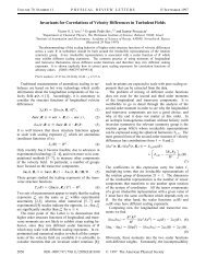
The average cut size <strong>of</strong> a reverse flow cyclone is obtained from a force balance for a particle<br />
by using rather crude assumptions about the flow field in the cyclone (Muschelknautz 1970).<br />
The force balance is applied on the surface <strong>of</strong> the outlet tube extended to the bottom <strong>of</strong> the<br />
cyclone (Figure 2.1). On this surface a constant radial velocity is assumed over the height.<br />
Hence the balance <strong>of</strong> radial drag force <strong>and</strong> centrifugal force yields the following cut size by<br />
assuming Stokes drag:<br />
D<br />
18 μ<br />
F ri i<br />
C = (2.1)<br />
2<br />
ρp<br />
Vϕi<br />
where ri is the radius <strong>of</strong> the outlet pipe, Vri is the radial velocity, <strong>and</strong> Vϕi is the tangential<br />
velocity. The assumption <strong>of</strong> a constant radial velocity is justified in most cases, hence it may<br />
be calculated from the volume flow rate V & <strong>and</strong> the surface <strong>of</strong> the exit tube extension with the<br />
height h i (Figure 2.1) as:<br />
V<br />
ri<br />
V&<br />
=<br />
2 π r<br />
7<br />
i<br />
V<br />
h<br />
i<br />
r<br />
(2.2)
However, the calculation <strong>of</strong> the tangential velocity <strong>of</strong> the particle is associated with several<br />
crude assumptions about the flow field. According to Muschelknautz (1970) the tangential<br />
velocity is obtained from a simple balance <strong>of</strong> the tangential momentum by accounting for<br />
inlet effects through the coefficient α <strong>and</strong> wall friction by the coefficient λ:<br />
V<br />
ϕ i<br />
Vi<br />
=<br />
ri<br />
α F + λ<br />
r<br />
e<br />
8<br />
h<br />
r<br />
i<br />
(2.3)<br />
The value F is the ratio <strong>of</strong> the cross-section <strong>of</strong> the inlet to that <strong>of</strong> the outlet tube <strong>and</strong> V i is the<br />
mean gas velocity in the outlet tube. This simple model predicts only one cut size <strong>of</strong> the<br />
reverse flow cyclone, neglecting details <strong>of</strong> the complex flow <strong>and</strong> turbulence, which is surely<br />
important for the separation <strong>of</strong> small particles. The grade efficiency curve <strong>of</strong> the cyclone may<br />
be only obtained by additional experimental information. Recently, Frank et al. (1999) have<br />
shown that the particle separation in cyclones may be effectively calculated using the<br />
Euler/Lagrange approach. However, the results showed that one essential physical<br />
phenomenon needs to be accounted for, namely particle agglomeration. Hence the predicted<br />
grade efficiency curve was shifted to larger particles compared to the measurements.<br />
h i<br />
inlet<br />
r i<br />
outlet tube<br />
V ri Vϕ i<br />
Figure 2.1: Geometry <strong>of</strong> a reverse flow cyclone <strong>and</strong> illustration <strong>of</strong> particle separation<br />
model<br />
F<br />
Dr<br />
F<br />
Z
Another example <strong>of</strong> engineering practice is the design <strong>of</strong> spray scrubbers for particle<br />
separation. Actually, the prediction <strong>of</strong> the separation efficiency <strong>of</strong> a spray scrubber requires<br />
much information about the droplet motion in such a device. The starting point for the lay-out<br />
is the single droplet capture efficiency. Its prediction however requires already detailed<br />
information about the flow field around the droplet. Depending on the droplet Reynolds<br />
number, the single droplet capture efficiency may vary over a wide range. The limiting cases<br />
are the viscous flow assumption (Red → 0) <strong>and</strong> potential theory (Red → ∞). Turbulence <strong>of</strong> the<br />
ambient gas phase is generally neglected. According to Schuch <strong>and</strong> Löffler (1978) the single<br />
droplet capture efficiency is given by:<br />
9<br />
b<br />
a ⎟ ⎛ ψ ⎞<br />
η = ⎜<br />
(2.4)<br />
⎝ ψ + ⎠<br />
where ψ is the inertial parameter or Stokes number obtained from:<br />
2<br />
ρp<br />
D p U rel<br />
ψ =<br />
(2.5)<br />
18 μ D<br />
F<br />
In Eq. 2.5, ρp is the particle material density, Dp the particle diameter, Dd the diameter <strong>of</strong> the<br />
droplet, <strong>and</strong> Urel is the local relative velocity between droplet <strong>and</strong> gas phase. The parameters a<br />
<strong>and</strong> b depend on the droplet Reynolds number (Schuch & Löffler 1978). For viscous flow (i.e.<br />
Red < 1) it was found:<br />
a = 0.65, b = 3.7<br />
<strong>and</strong> for potential flow (i.e. Red >> 1) the parameters are:<br />
a = 0.25, b = 2.0.<br />
The scale-up from the single-droplet capture efficiency to the prediction <strong>of</strong> the grade<br />
efficiency <strong>of</strong> a spray scrubber, however, is not straightforward <strong>and</strong> requires the calculation <strong>of</strong><br />
the droplet trajectories. In general, both the droplets <strong>and</strong> the particles to be separated have a<br />
certain size distribution, so that a simple engineering design <strong>of</strong> spray scrubber becomes<br />
impossible. In order to allow for an appropriate design, the flow field in the scrubber needs to<br />
be calculated for example using CFD (computational fluid dynamics). Subsequently a<br />
calculation <strong>of</strong> the droplet trajectories through the scrubber is required by accounting for the<br />
droplet <strong>and</strong> particle size distributions, which have an influence on the single droplet capture<br />
efficiency (see Eq. 2.4).<br />
The examples introduced here demonstrate, that CFD may considerably support the lay-out <strong>of</strong><br />
processes in the field <strong>of</strong> particle technology. For modelling the particle phase in a dispersed<br />
system the Lagrangian approach is most attractive since it allows a detailed consideration <strong>of</strong><br />
the relevant physical effects influencing the particle motion. In the following chapters a<br />
d
number <strong>of</strong> the relevant physical effects in dispersed two phase flows will be introduced <strong>and</strong><br />
discussed.<br />
3. Particle Motion in Fluids<br />
The motion <strong>of</strong> particles in fluids is described in a Lagrangian way by solving a set <strong>of</strong> ordinary<br />
differential equations along the trajectory in order to calculate the change <strong>of</strong> particle location<br />
<strong>and</strong> the linear <strong>and</strong> angular components <strong>of</strong> the particle velocity. This requires the consideration<br />
<strong>of</strong> all relevant forces acting on the particle. The equation <strong>of</strong> motion for small particles in a<br />
viscous quiescent fluid (i.e. for small particle Reynolds-numbers, which is also referred to as<br />
Stokes flow) goes back to the pioneering work <strong>of</strong> Basset (1988), Boussinesq (1985) <strong>and</strong><br />
Oseen (1927). Therefore, the equation <strong>of</strong> motion is mostly referred to as BBO-equation.<br />
Numerous publications deal with the extension <strong>of</strong> the BBO equation for turbulent flows. The<br />
thesis <strong>of</strong> Tchen (1949) was probably the first study on particle motion in turbulent flows<br />
based on the BBO equation. A rigorous derivation <strong>of</strong> the equation <strong>of</strong> motion for small<br />
particles in non-uniform flow has been performed by Maxey <strong>and</strong> Riley (1983). Neglecting the<br />
Faxen terms the equation proposed by Maxey <strong>and</strong> Riley (1983) for small particle Reynolds<br />
numbers is as follows:<br />
r<br />
d u P 18 μ<br />
m P =<br />
d t ρ D<br />
P<br />
+ 9<br />
F<br />
2<br />
P<br />
m<br />
P<br />
ρF<br />
μ<br />
π<br />
F<br />
r<br />
( u − u )<br />
m P<br />
ρ D<br />
P<br />
F<br />
r<br />
P<br />
P<br />
t<br />
∫<br />
0<br />
r<br />
D u F<br />
− m F + 0.<br />
5 m<br />
D t<br />
r r<br />
D u F d u P<br />
−<br />
D τ d τ<br />
dτ<br />
+<br />
( t − τ)<br />
10<br />
1 2<br />
F<br />
r<br />
⎛ D u<br />
⎜<br />
⎝ D t<br />
( m − m ) g<br />
P<br />
F<br />
F<br />
r<br />
d u<br />
−<br />
d t<br />
r<br />
P<br />
⎞<br />
⎟<br />
⎠<br />
(3.1)<br />
In the following section a possible extension <strong>of</strong> the BBO-equation for higher particle<br />
Reynolds numbers will be introduced. In addition other forces which might be relevant for<br />
certain conditions, such as for example transverse lift forces, will be introduced <strong>and</strong> their<br />
relevance will be analysed. Considering spherical particles <strong>and</strong> neglecting heat <strong>and</strong> mass<br />
transfer phenomena, the calculation <strong>of</strong> particle trajectories requires the solution <strong>of</strong> three<br />
ordinary differential equations when particle rotation is accounted for. Hence, the differential<br />
equations for calculating the particle location, <strong>and</strong> the linear <strong>and</strong> angular velocities in vector<br />
form are given by:<br />
m<br />
p<br />
r<br />
d x p r<br />
= u p<br />
dt<br />
(3.2)<br />
r<br />
d u r<br />
p<br />
= ∑ Fi<br />
dt<br />
(3.3)
p<br />
p<br />
3<br />
p<br />
I<br />
p<br />
r<br />
d ω<br />
dt<br />
p<br />
r<br />
= T<br />
p<br />
11<br />
p<br />
2<br />
p<br />
(3.4)<br />
where m = π / 6 ρ D is the particle mass, I = 0.<br />
1 m D is the moment <strong>of</strong> inertia for a<br />
sphere, i Fr represents the different relevant forces acting on the particle, <strong>and</strong> T r is the torque<br />
acting on a rotating particle due to the viscous interaction with the fluid.<br />
Analytical solutions for the different forces <strong>and</strong> the torque only are available for small particle<br />
Reynolds numbers (i.e. Stokes regime). An extension to higher Reynolds numbers is generally<br />
based on empirical correlations which are derived form experiments.<br />
3.1 Drag Force<br />
In most fluid-particle systems the drag force is dominating the particle motion <strong>and</strong> consists <strong>of</strong><br />
a friction <strong>and</strong> form drag. The extension <strong>of</strong> the drag force to higher particle Reynolds numbers<br />
is based on the introduction <strong>of</strong> a drag coefficient C D being defined as:<br />
where<br />
P<br />
expressed by:<br />
2<br />
P<br />
C<br />
D<br />
D = (3.5)<br />
ρF<br />
r<br />
2<br />
F<br />
r −<br />
2 ( u F u P ) A P<br />
A = π / 4 D is the cross-section <strong>of</strong> a spherical particle. The drag force is then<br />
r<br />
F<br />
3<br />
ρ<br />
m<br />
r<br />
r<br />
r<br />
( u F − u P ) u F − u P<br />
F P<br />
D = c D<br />
(3.6)<br />
4 ρP<br />
D P<br />
The drag coefficient is given as a function <strong>of</strong> the particle Reynolds number:<br />
r r<br />
ρF<br />
D P ( u F − u P )<br />
Re P =<br />
μ<br />
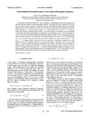
The dependence <strong>of</strong> the drag coefficient <strong>of</strong> a sphere (spherical particle) on the Reynolds<br />
number is shown in Figure 3.1 based on numerous experimental investigations (Schlichting<br />
1965). From this dependence one may identify several regimes which are associated with the<br />
flow characteristics around the sphere:<br />
• For small Reynolds numbers (i.e. Rep < 0.5) viscous effects are dominating <strong>and</strong> no<br />
F<br />
r<br />
(3.7)<br />
separation is observed. Therefore, an analytic solution for the drag coefficient is possible<br />
as proposed by Stokes (1851):<br />
This regime is <strong>of</strong>ten referred to as the Stokes-regime.<br />
24<br />
C D = . (3.8)<br />
Re<br />
p
• In the transition region (i.e. 0.5 < Rep < 1000) inertial effects become <strong>of</strong> increasing<br />
importance. Above a Reynolds number <strong>of</strong> about 24 the flow around the particle begins to<br />
separate. Initially this separation is symmetric (Clift et al.1978). It becomes unstable <strong>and</strong><br />
periodic above Rep ≈ 130. For this non-linear regime numerous correlations have been<br />
proposed (Clift et al. 1978, Crowe et al. 1998) which fit the experimental data more or less<br />
accurate. A frequently used correlation is that proposed by Schiller & Naumann (1933),<br />
which fits the data up to Rep = 1000 reasonably well (see Figure 3.1).<br />
P<br />
0.<br />
687 24<br />
( 1+<br />
0.<br />
15 Re P ) f D<br />
24<br />
c D = =<br />
(3.9)<br />
Re<br />
Re<br />
• Above Rep ≈ 1000 the drag coefficient remains almost constant up to the critical Reynolds<br />
number, since the wake size <strong>and</strong> structure is not considerably changing. This regime is<br />
referred to as Newton-regime with:<br />
12<br />
P<br />
Cd ≈ 0.<br />
44<br />
(3.10)<br />
• At the critical Reynolds number (Recrit ≈ 2,5 ⋅ 10 5 ) a drastic decrease <strong>of</strong> the drag<br />
coefficient is observed, being caused by the transition from a laminar to a turbulent<br />
boundary layer around the particle. This results in a decrease <strong>of</strong> the particle wake.<br />
• In the super-critical region (i.e. Rep > 4.0 ⋅ 10 5 ) the drag coefficient again increases<br />
continuously. For most practical particulate flows however this region is not relevant.<br />
C D [-]<br />
10 2<br />
10 1<br />
10 0<br />
10 -1<br />
10 -1<br />
10 0<br />
10 1<br />
10 2<br />
Re P [-]<br />
M e a s u r e m e n t<br />
S t o k e s<br />
S t a n d a r d C o r r e l a t i o n<br />
Newton<br />
Figure 3.1: Drag coefficient as a function <strong>of</strong> particle Reynolds number, comparison <strong>of</strong><br />
10 3<br />
experimental data with the correlation for the different regimes (The st<strong>and</strong>ard<br />
correlation corresponds to Eq. 3.9)<br />
10 4<br />
10 5<br />
10 6
The drag coefficient may be altered by numerous other physical effects, such as turbulence <strong>of</strong><br />
the flow, surface roughness <strong>of</strong> the particle, particle shape, wall effects, compressibility <strong>of</strong> the<br />
fluid, rarefaction effects, which in general can be only accounted for by empirical correction<br />
factors or functions being derived from detailed experiments.<br />
The turbulence level <strong>of</strong> the ambient flow essentially causes a reduction <strong>of</strong> the critical<br />
Reynolds number as shown by Torobin <strong>and</strong> Gauvin (1961). With increasing turbulence<br />
intensity the transition from laminar to turbulent boundary layer is shifted towards smaller<br />
particle Reynolds numbers.<br />
A surface roughness on a spherical particle also results in a reduction <strong>of</strong> the critical Reynolds<br />
number (Sawatzki 1961).<br />
The consideration <strong>of</strong> the particle shape in the calculation <strong>of</strong> particle motion is rather difficult,<br />
since it requires actually the solution <strong>of</strong> additional ordinary differential equations for the<br />
particle orientation <strong>and</strong> a projection <strong>of</strong> the forces with regard to the relative motion. Such an<br />
approach was recently introduced by Rosendahl (1998). Therefore, most compuations rely on<br />
the assumption <strong>of</strong> spherical particles. A simplified approach to consider a non-sphericity <strong>of</strong><br />
the particle may be based on the use <strong>of</strong> modified drag coefficients, which are provided for<br />
different non-spherical particles for example by Haider & Levenspiel (1989) <strong>and</strong> Thompson<br />
& Clark (1991). It is however very little known about particle shape effects in the other<br />
forces, such as added mass <strong>and</strong> transverse lift forces.<br />
The motion <strong>of</strong> particles in the vicinity <strong>of</strong> a rigid wall results in an increase <strong>of</strong> the drag<br />
coefficient <strong>and</strong> is additionally associated with a transverse lift force. Analytic solutions for the<br />
wall effect are again only available for very small particle Reynolds numbers. The particle<br />
motion normal to a wall (Figure 3.2a)) was for example considered by Brenner (1961) <strong>and</strong> a<br />
wall-parallel motion (Figure 3.2b)) was analysed by Goldman et al. (1967). The first order<br />
solution for a particle moving towards a wall, which is valid for large distances from the wall,<br />
is given by (Brenner 1961):<br />
C<br />
9 R<br />
≅ 1+<br />
(3.11)<br />
8 h<br />
CD P<br />
D,<br />
Stokes<br />
For a non-rotating particle moving parallel to a wall in a quiescent fluid the increase <strong>of</strong> the<br />
drag is predicted by an asymptotic solution proposed by Faxen (1923) for large distances from<br />
the wall:<br />
C<br />
C<br />
D<br />
D,<br />
Stokes<br />
3<br />
4<br />
5<br />
−1<br />
⎡ 9 ⎛ R P ⎞ 1 ⎛ R P ⎞ 45 ⎛ R P ⎞ 1 ⎛ R ⎤<br />
P ⎞<br />
= −<br />
(3.12)<br />
⎢1<br />
⎢⎣<br />
⎜<br />
16 ⎝<br />
h<br />
⎟ + ⎜<br />
⎠ 8 ⎝<br />
h<br />
⎟<br />
⎠<br />
− ⎜<br />
256 ⎝<br />
13<br />
h<br />
⎟<br />
⎠<br />
− ⎜<br />
16 ⎝<br />
h<br />
⎟ ⎥<br />
⎠ ⎥⎦
The two results are shown in Figure 3.3 as a function <strong>of</strong> the normalised gap between particle<br />
<strong>and</strong> wall (i.e. a/RP). For large wall distance the curves approach unity <strong>and</strong> a finite value is<br />
obtained for a/RP → 0. It should be noted that wall effects will be additionally affected by<br />
particle rotation <strong>and</strong> a shear flow in the vicinity <strong>of</strong> the wall Goldman et al. (1967).<br />
D P<br />
u P<br />
h<br />
Figure 3.2: Illustration <strong>of</strong> wall effects, a) motion normal to a wall, b) motion parallel to a<br />
wall<br />
C D / C D,Stokes<br />
3.5<br />
3.0<br />
2.5<br />
2.0<br />
1.5<br />
14<br />
h<br />
D P<br />
u P<br />
1.0<br />
1E-3 0.01 0.1 1 10<br />
a / R P<br />
a<br />
normal to the wall<br />
p a r a l l e l t o t h e w a l l<br />
Figure 3.3: Modification <strong>of</strong> drag coefficient for a particle moving normal <strong>and</strong> parallel to a<br />
wall (Eqs. 3.11 <strong>and</strong> 3.12)<br />
Rarefaction effects become <strong>of</strong> importance in a low pressure environment or when the<br />
particles are very small. In such a situation the gas flow around the particle cannot be<br />
regarded as a continuum, instead the particle motion is induced by collisions <strong>of</strong> gas molecules<br />
with the particle surface. This results in a reduction <strong>of</strong> the drag coefficient. The importance <strong>of</strong><br />
rarefaction effects may be estimated based on the ratio <strong>of</strong> the mean free path <strong>of</strong> the gas<br />
molecules to the particle diameter, which is the particle Knudsen number:
Kn<br />
λ<br />
= (3.13)<br />
p<br />
D p<br />
The mean free path <strong>of</strong> the gas molecules λ can be calculated according to kinetic theory <strong>of</strong><br />
gases from:<br />
μ<br />
F<br />
λ =<br />
(3.14)<br />
0. 499 c ρ<br />
where c Mol is the mean relative velocity between gas molecules given by:<br />
Mol<br />
15<br />
F<br />
1/<br />
2<br />
8 p<br />
c Mol ⎟<br />
F<br />
⎟<br />
⎛ ⎞<br />
= ⎜<br />
(3.15)<br />
⎝ π ρ ⎠<br />
<strong>and</strong> p is the pressure. For atmospheric conditions (i.e. p = 1.0 bar, T = 293 K) the mean free<br />
path is about 0.06 µm. A classification <strong>of</strong> the different flow regimes in rarefied conditions or<br />
for very small particles may be based on the Knudsen number <strong>and</strong> is summarised in Table 3.1.<br />
In the Stokes regime which is generally valid for very small particles, the reduction <strong>of</strong> the<br />
drag coefficient may be accounted for by a correction function, the so-called Cunningham<br />
correction, resulting in a modified drag (Davies 1945):<br />
C<br />
D<br />
C D,<br />
Stokes<br />
CD,<br />
Stokes<br />
= =<br />
(3.16)<br />
⎧<br />
⎛ 0.<br />
55 ⎞⎫<br />
Cu<br />
1+<br />
Kn P ⎨2.<br />
514 + 0.<br />
8 exp<br />
⎜<br />
⎜−<br />
⎬<br />
⎩<br />
Kn ⎟<br />
⎝ P ⎠⎭<br />
This correlation is valid for 0.1 < Knp < 1000 <strong>and</strong> Rep < 0.25 <strong>and</strong> is only applicable for low<br />
particle Mach numbers (definition see below). Therefore, it is <strong>of</strong>ten used in particle<br />
technology, as for example when considering the separation <strong>of</strong> fine particles from a gas. The<br />
Cunningham correction, i.e. 1/Cu, is plotted in Figure 3.4 as a function <strong>of</strong> the Knudsen<br />
number. It is obvious, that a considerable reduction <strong>of</strong> the drag coefficient occurs for Knp ><br />
0.015.<br />
Flow Regime Range <strong>of</strong> Knudsen number<br />
Continuum flow 0 < KnP < 0.015<br />
Slip flow 0.015 < KnP < 0.15<br />
Transition flow 0.15 < KnP < 4.5<br />
Free molecular flow 4.5 < KnP < ∞<br />
Table 3.1 Different regimes <strong>of</strong> rarefied flows with respect to particle motion
C D / C D, Stokes [-]<br />
1<br />
0.1<br />
0.01<br />
1E-3<br />
1E-4<br />
10<br />
- 3<br />
- 2<br />
10<br />
10 -1<br />
16<br />
1 0 0<br />
Kn [-]<br />
Figure 3.4: Modification <strong>of</strong> the drag coefficient due to rarefaction effects (Eq. 3.16)<br />
The compressibility <strong>of</strong> the fluid (i.e. a gas) becomes <strong>of</strong> importance when the relative velocity<br />
becomes so large that the particle Mach number increases beyond 0.3. In such a situation<br />
compression waves or even shock waves (for Map > 1) are initiated by the particle motion<br />
which cause an increase <strong>of</strong> the drag for large particle Reynolds numbers. The particle Mach<br />
number is defined as:<br />
Ma<br />
where a is the speed <strong>of</strong> sound given by:<br />
p<br />
1 0 1<br />
1 0 2<br />
10 3<br />
r r<br />
u F − u P<br />
= (3.17)<br />
a<br />
a = γ R T<br />
(3.18)<br />
In Eq. (3.18), γ is the ratio <strong>of</strong> the specific heats, R is the universal gas constant, <strong>and</strong> T the<br />
absolute temperature <strong>of</strong> the gas.<br />
Numerous correlations, which are mostly based on experimental studies, are proposed to<br />
account for compressibility effects, as for example the following expression proposed by<br />
Carlson <strong>and</strong> Hoglund (1964):<br />
where D,<br />
0<br />
⎛ 0.<br />
427 3.<br />
0 ⎞<br />
1.<br />
0 + exp<br />
⎜<br />
⎜−<br />
−<br />
⎟<br />
4.<br />
63 0.<br />
88<br />
⎝ Ma P ReP<br />
C =<br />
⎠<br />
D CD,<br />
0<br />
(3.19)<br />
Ma ⎧<br />
⎛ ⎞⎫<br />
P<br />
ReP<br />
1.<br />
0 + ⎨3.<br />
82 + 1.<br />
28 exp ⎜<br />
⎜−<br />
1.<br />
25 ⎟<br />
⎟⎬<br />
ReP<br />
⎩<br />
⎝ Ma P ⎠⎭<br />
C is the drag coefficient given by Eqs. 3.9 <strong>and</strong> 3.10. The term in the nominator<br />
accounts for compressibility, while the denominator accounts for rarefaction effects. The drag
coefficient versus Mach number is plotted in Figure 3.5 for a small <strong>and</strong> large particle<br />
Reynolds number. For small particles the drag coefficient is decreasing due to rarefaction<br />
effects, whereas it increases for large particles beyond a Mach number <strong>of</strong> about 0.6 due to<br />
compressibility effects. Other expressions for the drag coefficient including rarefaction <strong>and</strong><br />
compressibility effects are given by Crowe et al. (1998).<br />
C D<br />
10<br />
1<br />
0 1 2 3 4<br />
17<br />
Ma P<br />
R e P = 1<br />
R e P = 100<br />
Figure 3.5: Modification <strong>of</strong> the drag coefficient due to rarefaction <strong>and</strong> compressibility<br />
effects for small <strong>and</strong> large particles (Eq. 3.19)<br />
3.2 Pressure Gradient <strong>and</strong> Buoyancy Force<br />
The local pressure gradient in the flow gives rise to an additional force in the direction <strong>of</strong> the<br />
pressure gradient. Combining the pressure gradient with the shear stress in the fluid, one<br />
obtains:<br />
F<br />
p<br />
m<br />
=<br />
ρ<br />
p<br />
p<br />
r<br />
( − ∇ p + ∇ τ)<br />
(3.20)<br />
From the Navier-Stokes equation <strong>of</strong> the fluid the pressure gradient <strong>and</strong> the shear stress can be<br />
related to the fluid acceleration <strong>and</strong> the gravity force:<br />
r<br />
r ⎛ D u F r ⎞<br />
− ∇ p + ∇ τ = ρF<br />
⎜ − g ⎟<br />
⎝ D t ⎠<br />
Hence the total pressure force is obtained in the following form:<br />
r<br />
r<br />
ρF<br />
⎛ D u F r ⎞<br />
Fp<br />
= m p ⎜ − g ⎟<br />
ρp<br />
⎝ D t ⎠<br />
(3.21)<br />
(3.22)
The first term <strong>of</strong> Eq. 3.22 represents the fluid acceleration <strong>and</strong> the second one is the buoyancy<br />
force. It is obvious, that in gas solid flows the pressure force may be neglected since ρF/ρp
calculations <strong>of</strong> Sommerfeld (1996) have shown that the consideration <strong>of</strong> the Basset force<br />
increases the computational time by a factor <strong>of</strong> about 10. An analysis <strong>of</strong> the importance <strong>of</strong> the<br />
different forces, especially added mass <strong>and</strong> Basset force, in an oscillatory flow field for<br />
different density ratios will be provided below.<br />
3.4 Body Forces<br />
Body forces are the gravity force, the Coulomb force, which arises when a particle moves in<br />
an electric field, as for example in an electrostatic precipitator or the thermophoretic force<br />
which becomes <strong>of</strong> importance when a small particle moves in a flow with a high temperature<br />
gradient.<br />
The gravity force is:<br />
r r<br />
= m g . (3.28)<br />
Fg p<br />
The Coulomb force acting on a particle moving in an electric field with a field intensity E r is<br />
given by:<br />
r<br />
= −q<br />
E<br />
(3.29)<br />
FC p<br />
where qp is the charge <strong>of</strong> the particle. In an electrostatic precipitator, for example, the particles<br />
are charged by an ion-bombardment created by a negative corona discharge in the vicinity <strong>of</strong><br />
a charging wire. The charging <strong>of</strong> the particles is caused by two mechanisms: field charging<br />
<strong>and</strong>/or diffusion charging.<br />
Field charging occurs due to the convective motion <strong>of</strong> the ions <strong>and</strong> is relevant for particles<br />
larger than about 0.5 to 1 µm. The saturation charge for a spherical particle is:<br />
q p 0 p 0<br />
2<br />
= π ε D E p<br />
(3.30)<br />
where ε0 is the permittivity <strong>of</strong> the free space, E0 is the electric field strength in the charging<br />
region <strong>and</strong> p = 3 for conducting particles <strong>and</strong> p = 1.5 to 2.0 for non-conducting particles.<br />
Diffusion charging is the result <strong>of</strong> the thermal motion <strong>of</strong> the ions <strong>and</strong> is relevant for particles<br />
with a diameter smaller than about 0.2 µm. The rate <strong>of</strong> charge increase due to diffusion<br />
charging is given by:<br />
q<br />
P<br />
( t)<br />
= 4 π ε<br />
0<br />
k ⋅ T<br />
e<br />
x<br />
2<br />
2<br />
⎧ x c N ⎫ 0 e t<br />
ln ⎨1<br />
+ ⎬<br />
⎩ 8 ε0<br />
k T ⎭<br />
19<br />
(3.31)<br />
where k is the Boltzmann constant, e is the elementary charge, N0 is the number density <strong>of</strong> the<br />
ions, c is the mean fluctuating velocity <strong>of</strong> the ions, t is the time, <strong>and</strong> T the absolute<br />
temperature <strong>of</strong> the gas. More details about particle charging <strong>and</strong> their motion in an electric<br />
field may be found in the book <strong>of</strong> White (1963).
3.5 Slip-Shear Lift Force<br />
Particles moving in a shear layer experience a transverse lift force due to the non-uniform<br />
relative velocity over the particle <strong>and</strong> the resulting non-uniform pressure distribution. The lift<br />
force is acting towards the direction <strong>of</strong> higher slip velocity (Figure 3.6). An expression for the<br />
slip shear lift force for a freely rotating particle moving at constant velocity in a two-<br />
dimensional shear flow at low Reynolds number was derived from an asymptotic expansion<br />
by Saffman (1965, 1968):<br />
2<br />
D<br />
y<br />
p<br />
0.<br />
5 ∂ u F<br />
FLS, Saff = 6.<br />
46 ( ρF<br />
μ F ) ( u F − u p )<br />
(3.32)<br />
4<br />
∂ y<br />
Extending this expression to a three dimensional flow <strong>and</strong> introducing a correction function<br />
for higher particle Reynolds numbers yields:<br />
r<br />
⎛ 1 ⎞<br />
2<br />
r r r<br />
FLS = 1.<br />
615 D P F F ⎜ r ⎟ F P F P S<br />
⎝ ωF<br />
⎠<br />
0.<br />
5<br />
1/<br />
2 ( ρ μ ) ⎜ ⎟ { ( u − u ) × ω } f (Re , Re )<br />
20<br />
(3.34)<br />
Here the fluid rotation is obtained from:<br />
r<br />
ω<br />
r<br />
= rot u<br />
r<br />
= ∇ × u<br />
(3.35)<br />
F<br />
F<br />
Introducing now a lift coefficient in Eq. (3.34) gives the following impression for the slip-<br />
shear lift force:<br />
with the lift coefficient:<br />
r<br />
ρ<br />
2<br />
π<br />
4<br />
F<br />
r r r<br />
( u − u ) × )<br />
F 2<br />
FLS = D p CLS<br />
D P F p ωF<br />
0.<br />
5<br />
S<br />
( Re , Re )<br />
(3.36)<br />
4.<br />
1126<br />
C LS = f p s<br />
(3.37)<br />
Re<br />
The correction function f (Rep, Res) proposed by Mei (1992) on the basis <strong>of</strong> calculations<br />
performed by D<strong>and</strong>y <strong>and</strong> Dwyer (1990) for a particle Reynolds number in the range 0.1 ≤ Rep<br />
≤ 100 is given by:<br />
with:<br />
F<br />
F<br />
LS<br />
LS,<br />
Saff<br />
=<br />
=<br />
1<br />
2<br />
( 1−<br />
0.<br />
3314 β )<br />
0.<br />
0524<br />
( Re , Re )<br />
F<br />
LS<br />
f p S = (3.38)<br />
FLS,<br />
Saff<br />
⎛ Re<br />
exp⎜−<br />
⎝ 10<br />
0.<br />
3314<br />
for :<br />
Re<br />
≤ 40<br />
1<br />
2 ( β Re ) for : Re ≥ 40<br />
P<br />
P<br />
⎞<br />
⎟ +<br />
⎠<br />
Re<br />
p<br />
β<br />
1<br />
2<br />
P<br />
P<br />
(3.39)<br />
S<br />
β = 0.<br />
5<br />
(3.40)<br />
Re
<strong>and</strong> the Reynolds number <strong>of</strong> the shear flow:<br />
Re<br />
S<br />
ρ<br />
=<br />
F<br />
D<br />
μ<br />
2<br />
p<br />
F<br />
21<br />
r<br />
ω<br />
F<br />
(3.41)<br />
The dependence <strong>of</strong> the lift coefficient on the particle Reynolds number with the shear<br />
Reynolds number as a parameter is shown in Figure 3.7. The horizontal lines indicate the<br />
values for the Saffman expression which agree with the lift coefficient in Eq. 3.37 only for<br />
small Reynolds numbers.<br />
Figure 3.6: Illustration <strong>of</strong> the slip-shear lift force<br />
C LS<br />
5<br />
4<br />
3<br />
2<br />
1<br />
uP<br />
FLS<br />
R e S = 1<br />
R e S = 10<br />
R e S = 1 0 0<br />
0<br />
0.1 1 10 100 1000<br />
Re P<br />
Figure 3.7: Lift coefficient as a function <strong>of</strong> particle Reynolds number with the shear<br />
Reynolds number as a parameter (The horizontal line indicate the lift coefficient<br />
<strong>of</strong> the Saffman lift force, Eq. 3.37 with ( Re , Re ) 1.<br />
0<br />
f p S = ).
3.6 Slip-Rotation Lift Force<br />
Particles which are not freely rotating in a flow may also experience a lift force due to their<br />
rotation, the so-called Magnus force. High particle rotations may for example be induced by<br />
particle-wall collision frequently occurring in pipe or channel flows. The rotation <strong>of</strong> the<br />
particle results in a deformation <strong>of</strong> the flow field around the particle, associated with a shift <strong>of</strong><br />
the stagnation points <strong>and</strong> a transverse lift force (Figure 3.8). An analytic expression for the<br />
slip-rotation lift force in the case <strong>of</strong> small particle Reynolds numbers was derived by Rubinow<br />
<strong>and</strong> Keller (1961):<br />
r<br />
F<br />
where Ω r is the relative rotation given by:<br />
LR<br />
r<br />
= π R ρ<br />
(3.42)<br />
3<br />
p<br />
F<br />
r 1 r<br />
Ω = ∇ × u<br />
2<br />
r r { Ω × ( u − u ) }<br />
F<br />
22<br />
F<br />
r<br />
− ω<br />
p<br />
p<br />
(3.43)<br />
Also the slip-rotation lift force may be extended for higher particle Reynolds numbers by<br />
introducing a lift coefficient (Crowe et al. 1998):<br />
r<br />
F LR<br />
ρF<br />
π 2<br />
= D p C LR<br />
2 4<br />
r r<br />
u F − u p<br />
r r r<br />
Ω × ( u F − u p )<br />
r<br />
Ω<br />
(3.44)<br />
For small particle Reynolds numbers the lift coefficient is obtained according to Rubinow <strong>and</strong><br />
Keller (1961) in the form:<br />
with:<br />
r<br />
D p Ω Re<br />
C LR = r r =<br />
u − u Re<br />
Re<br />
R<br />
F<br />
ρ<br />
=<br />
F<br />
p<br />
D<br />
μ<br />
2<br />
p<br />
F<br />
r<br />
Ω<br />
R<br />
p<br />
(3.45)<br />
(3.46)<br />
being the Reynolds number <strong>of</strong> particle rotation. A lift coefficient for higher particle Reynolds<br />
numbers requires experimental information. Recently, Oesterlé <strong>and</strong> Bui Dinh (1998)<br />
introduced the following correlation based on available literature data <strong>and</strong> additional<br />
experiments for Rep < 140:<br />
0.<br />
4 0.<br />
3<br />
( − 0.<br />
05684 ⋅ Re ⋅ Re ) for : Re < 140<br />
⎛ Re R ⎞<br />
CLR = 0.<br />
45 + ⎜ − 0.<br />
45 exp<br />
R P<br />
P<br />
Re ⎟<br />
(3.47)<br />
⎝ P ⎠<br />
The lift coefficient <strong>of</strong> particle rotation as a function <strong>of</strong> the particle Reynolds number with the<br />
Reynolds number <strong>of</strong> particle rotation as a parameter is shown in Figure 3.9. The upper <strong>and</strong>
lower straight lines correspond to the result <strong>of</strong> Rubinow <strong>and</strong> Keller (1961) given by Eq. 3.45.<br />
It is obvious that this expression only holds for small particle Reynolds numbers.<br />
Figure 3.8: Illustration <strong>of</strong> the slip-rotation lift force acting on a stationary particle<br />
C L R<br />
10 2<br />
10 1<br />
10 0<br />
- 1<br />
10<br />
- 2<br />
10<br />
- 3<br />
10<br />
- 1<br />
10<br />
10 0<br />
ωP<br />
10 3<br />
10 4 R e = 1<br />
R<br />
R e = 10<br />
R<br />
R e = 100<br />
R<br />
R e = 1 0 0 0<br />
R<br />
23<br />
1 0 1<br />
Re P<br />
Figure 3.9: Lift coefficient <strong>of</strong> particle rotation as a function <strong>of</strong> particle Reynolds number<br />
with the Reynolds number <strong>of</strong> particle rotation as a parameter. The lower <strong>and</strong><br />
upper straight lines correspond to the result <strong>of</strong> Rubinow <strong>and</strong> Keller (1961) for<br />
ReR = 1 <strong>and</strong> ReR = 1000, respectively.<br />
FLR<br />
10 2<br />
10 3
3.7 Torque<br />
The torque acting on a rotating particle due to the interaction with the fluid was also derived<br />
by Rubinow <strong>and</strong> Keller (1961) for a stagnant fluid <strong>and</strong> small particle Reynolds numbers:<br />
T<br />
3<br />
ω μ π − =<br />
r<br />
r<br />
(3.48)<br />
F p D<br />
This expression may be extended for a three-dimensional flow <strong>and</strong> for higher Reynolds<br />
numbers by introducing a rotational coefficient:<br />
5<br />
24<br />
p<br />
r ρ ⎛ D ⎞ r r<br />
F p<br />
T =<br />
⎜<br />
⎟ C R Ω Ω<br />
(3.49)<br />
2 ⎝ 2 ⎠<br />
From the numerical simulations <strong>of</strong> Dennis et al. (1980) <strong>and</strong> experimental data <strong>of</strong> Sawatzki<br />
(1970) the rotational coefficient for higher particle Reynolds numbers is found to be:<br />
12.<br />
9 128.<br />
4<br />
= +<br />
for : 32 < Re < 1000<br />
(3.50)<br />
0.<br />
5<br />
Re Re<br />
CR R<br />
R<br />
R<br />
In the case <strong>of</strong> smaller particle Reynolds numbers the result <strong>of</strong> Rubinow <strong>and</strong> Keller (1961)<br />
yields:<br />
64 π<br />
= for : Re < 32<br />
(3.51)<br />
Re<br />
CR R<br />
R<br />
The comparison <strong>of</strong> the above correlation (Eqs. 3.50 <strong>and</strong> 3.51) with the simulations (Dennis et<br />
al. 1980) <strong>and</strong> the experiments (Sawatzki 1970) give a good agreement as shown in Figure<br />
3.10.<br />
C R<br />
1000<br />
100<br />
10<br />
1<br />
C o r r e l a t i o n s<br />
Rubinow und Keller (1961)<br />
Dennis et al. (1980)<br />
Sawatzki (1970)<br />
0.1<br />
0.1 1 1 0 100 1000<br />
Re R<br />
Figure 3.10: Coefficient <strong>of</strong> particle rotation as a function <strong>of</strong> particle rotational Reynolds<br />
number according to Eqs. 3.50 <strong>and</strong> 3.51 <strong>and</strong> comparison with experiments<br />
(Sawatzki 1970) <strong>and</strong> numerical calculations (Dennis et al. 1980)
3.8 Response Time <strong>and</strong> Stokes Number<br />
The particle (velocity or momentum) response time may be used to characterise the capability<br />
<strong>of</strong> particles to follow a sudden velocity change in the flow, occurring for example in large<br />
scale vertical structures or turbulent eddies. In order to derive the particle response time the<br />
equation <strong>of</strong> motion is used by only considering the drag force.<br />
du<br />
25<br />
( u u )<br />
ρ π<br />
= p<br />
(3.52)<br />
2 4<br />
p F 2<br />
m p<br />
D pC<br />
D u F − u p F −<br />
dt<br />
Dividing by the particle mass <strong>and</strong> introducing the particle Reynolds number gives:<br />
du<br />
dt<br />
p<br />
18 μ CD<br />
Re p<br />
= ( u F − u p )<br />
(3.53)<br />
ρ D 24<br />
p<br />
F<br />
2<br />
p<br />
The term CD Rep/24 corresponds to the non-linear term in the drag coefficient fD <strong>and</strong> the first<br />
term <strong>of</strong> Eq. 3.53 has the dimension <strong>of</strong> a time, the particle response time:<br />
Hence the equation <strong>of</strong> motion becomes:<br />
du<br />
dt<br />
2<br />
ρp<br />
D p<br />
τ p =<br />
(3.54)<br />
18 μ f<br />
p<br />
p<br />
F<br />
D<br />
( u − u )<br />
1<br />
= F p<br />
(3.55)<br />
τ<br />
The solution <strong>of</strong> this equation for a simplified case, namely a constant fluid velocity uF <strong>and</strong> an<br />
initial particle velocity <strong>of</strong> zero is:<br />
⎛ ⎛ ⎞⎞<br />
⎜ ⎜<br />
t<br />
u ⎟⎟<br />
p = u F 1−<br />
exp −<br />
(3.56)<br />
⎜ ⎜ ⎟⎟<br />
⎝ ⎝ τp<br />
⎠⎠<br />
From this equation it is obvious that τp is the time required for a particle released with zero<br />
velocity into a flow with uF to reach 63.2 % <strong>of</strong> the flow velocity all illustrated in Figure 3.11.<br />
u F<br />
0.632 u F<br />
τ P<br />
u P<br />
Figure 3.11: Graphical illustration <strong>of</strong> the particle response time<br />
time
In the Stokes-regime the particle response time becomes:<br />
since fD approaches unity.<br />
τ<br />
p<br />
ρp<br />
=<br />
18 μ<br />
D 2<br />
p<br />
26<br />
(3.57)<br />
The Stokes number is the ratio <strong>of</strong> the particle response time to a characteristic time scale <strong>of</strong><br />
the flow.<br />
3.9 Importance <strong>of</strong> the Different Forces<br />
τp<br />
St = (3.58)<br />
τ<br />
F<br />
In order to estimate the importance <strong>of</strong> the different forces, especially the importance <strong>of</strong> added<br />
mass <strong>and</strong> Basset force, acting on a particle in a turbulent flow, Hjelmfeld & Mockros (1966)<br />
have performed an analysis for an oscillatory flow field. The starting point <strong>of</strong> their analysis<br />
was the Stokes form <strong>of</strong> the equation <strong>of</strong> motion given by:<br />
m<br />
P<br />
d u<br />
P<br />
d t<br />
18 μ<br />
=<br />
ρ D<br />
P<br />
+ 9<br />
F<br />
2<br />
P<br />
Rearranging this equation results in:<br />
d u<br />
d t<br />
ρ<br />
F<br />
π<br />
m<br />
μ<br />
F<br />
P<br />
( u − u )<br />
ρ<br />
m<br />
P<br />
F<br />
P<br />
D<br />
P<br />
P<br />
t<br />
∫ ∞<br />
−<br />
− m<br />
d u<br />
F<br />
d τ<br />
F<br />
d u<br />
d t<br />
d u P<br />
−<br />
d τ<br />
( t − τ)<br />
F<br />
1 2<br />
+<br />
0.<br />
5 m<br />
dτ<br />
F<br />
⎛ d u<br />
⎜<br />
⎝ d t<br />
t<br />
t<br />
d u P d τ<br />
d u F d u<br />
+ a u P + c ∫ dτ<br />
= a u + b + c ∫<br />
F<br />
d u P ⎞<br />
− ⎟<br />
d t ⎠<br />
d τ<br />
dτ<br />
(3.59)<br />
P F<br />
(3.60)<br />
1 2<br />
F<br />
1 2<br />
−∞<br />
( t − τ)<br />
d t −∞<br />
( t − τ)<br />
with the coefficients a, b <strong>and</strong> c defined by:<br />
a<br />
F F<br />
= ,<br />
2<br />
( ρ ρ + 0.<br />
5)<br />
D<br />
P<br />
18<br />
F<br />
μ<br />
ρ<br />
P<br />
3<br />
b = ,<br />
2<br />
( ρ ρ + 0.<br />
5)<br />
P<br />
F<br />
c<br />
9<br />
F<br />
= (3.61)<br />
μ<br />
( ρ P ρ F + 0.<br />
5)<br />
π ρ F<br />
The velocities <strong>of</strong> the particles <strong>and</strong> the fluid are expressed by Fourier integrals:<br />
u<br />
∞<br />
= ∫<br />
0<br />
∞<br />
= ∫<br />
0<br />
F ( ς cosωt<br />
+ λ sin ωt)<br />
dω,<br />
u P ( σ cosωt<br />
+ ϕ sin ωt)<br />
dω<br />
(3.62)<br />
where ω is the frequency <strong>of</strong> oscillation. Introducing these Fourier integrals into the equation<br />
<strong>of</strong> motion <strong>of</strong> the particles (Eq. 3.60) yields the amplitude ratio (i.e. amplitude <strong>of</strong> particle<br />
velocity over that <strong>of</strong> the fluid) <strong>and</strong> the phase angle (i.e. lag <strong>of</strong> particle response) in the<br />
following form:
2 2<br />
( 1 + f ) + f<br />
η =<br />
,<br />
The functions f1 <strong>and</strong> f2 are obtained as:<br />
f<br />
f<br />
2<br />
1<br />
1<br />
2<br />
( ω + c 0.<br />
5 π ω)(<br />
b −1)<br />
( ) ( ) 2<br />
2<br />
a + c 0.<br />
5 π ω + ω + c 0.<br />
5 π ω<br />
27<br />
−1⎧<br />
f ⎫ 2<br />
β = tan ⎨ ⎬<br />
(3.63)<br />
⎩1+<br />
f1<br />
⎭<br />
ω<br />
= (3.64)<br />
( a + c 0.<br />
5 π ω)(<br />
b −1)<br />
ω<br />
= (3.65)<br />
( ) ( ) 2<br />
2<br />
a + c 0.<br />
5 π ω + ω + c 0.<br />
5 π ω<br />
The parameter used to characterise the particle response is a modified Stokes number given<br />
by:<br />
N<br />
μ<br />
F<br />
s = (3.66)<br />
2<br />
ρF<br />
ω D p<br />
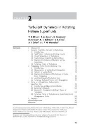
The result <strong>of</strong> this analysis is shown in Figure 3.12 for three kinds <strong>of</strong> particles, namely copper<br />
<strong>and</strong> glass particles in air <strong>and</strong> air bubbles in water, by considering the different forces. For the<br />
three cases the amplitude ratio <strong>and</strong> the phase angle is plotted versus the modified Stokes<br />
number. It is obvious that for copper particles <strong>and</strong> glass beads the added mass, the pressure<br />
force, <strong>and</strong> the Basset term have almost no effect on the amplitude ratio. However,<br />
considerable differences are observed in the phase angle for Ns < 5, which means for large<br />
particles or high frequencies <strong>of</strong> the oscillatory fluid motion. Only the added mass is not <strong>of</strong><br />
great importance <strong>and</strong> may be neglected without considerable error. Considering a 100 μm<br />
particle the pressure force <strong>and</strong> the Basset term become <strong>of</strong> importance for oscillation<br />
frequencies larger than about 310 Hz. For bubbly flows large differences in the response arise<br />
for Ns < 1.0. However, for this case the Basset term may be neglected without introducing<br />
very large errors. The added mass <strong>and</strong> the pressure force on the other h<strong>and</strong> are <strong>of</strong> great<br />
importance.
Figure 3.12: Particle response in an oscillatory flow field, influence <strong>of</strong> the different forces on<br />
the amplitude ratio (left column) <strong>and</strong> the phase angle (right column) for: a)<br />
copper particles in air, b) glass beads in air, c) air bubbles in water<br />
28
4. Particle-Wall Collisions<br />
Particle-wall collisions become <strong>of</strong> importance in confined flows, such as pneumatic<br />
conveying or particle separation in cyclones. In pneumatic conveying, for example, the<br />
momentum loss <strong>of</strong> a particle caused by an inelastic wall impact is associated with a re-<br />
acceleration <strong>of</strong> the particle after rebound. Hence, momentum is extracted from the fluid phase<br />
for this acceleration, causing an additional pressure loss. This pressure loss depends on the<br />
average wall collision frequency or mean free path between subsequent particle-wall<br />
collisions. The wall collision frequency is mainly determined by the following parameters:<br />
• particle mass loading<br />
• dimensions <strong>of</strong> the confinement, e.g. pipe diameter in pneumatic conveying<br />
• particle response time or response distance<br />
• conveying velocity <strong>and</strong> turbulence intensity<br />
• particle shape <strong>and</strong> wall roughness<br />
• combination <strong>of</strong> particle <strong>and</strong> wall material.<br />
A first estimate <strong>of</strong> the importance <strong>of</strong> particle-wall collisions may be based on the ratio <strong>of</strong> the<br />
particle response distance λp to the dimension <strong>of</strong> the confinement, e.g. the diameter <strong>of</strong> the<br />
pipe D. The particle response distance can be estimated from the following equation:<br />
2<br />
p D p<br />
⋅<br />
ρ<br />
λ p = w t<br />
(4.1)<br />
18 μ f<br />
F<br />
where wt is the terminal velocity <strong>of</strong> the particle. For the case λp is larger than the dimension <strong>of</strong><br />
the confinement D, the particles are not able to respond to the flow, before they collide with<br />
the opposite wall, hence their motion is dominated by wall collisions. In addition to the above<br />
mentioned effects the wall collision process may be affected by hydrodynamic interaction<br />
which eventually causes a deceleration <strong>of</strong> the particle before impact (see above, the section on<br />
wall effects). This effect however is only <strong>of</strong> importance for viscous fluids <strong>and</strong> hence small<br />
particle Reynolds numbers.<br />
4.1 Velocity Change During Wall Collisions<br />
In the following the so-called hard sphere model for the wall collision will be described which<br />
implies a negligible particle deformation during the impact process. Moreover, Coulomb’s<br />
law <strong>of</strong> friction is assumed to hold for a sliding collision. For an inelastic collision process, one<br />
may identify a compression <strong>and</strong> a recovery period. The change <strong>of</strong> the particles translational<br />
<strong>and</strong> rotational velocities during the bouncing process can be calculated from the momentum<br />
D<br />
29
equations <strong>of</strong> classical mechanics (Crowe et al. 1998). Three types <strong>of</strong> collisions may be<br />
distinguished:<br />
Type 1: The particle stops sliding in the compression period.<br />
Type 2: The particle stops sliding in the recovery period.<br />
Type 3: The particle continues to slide along the wall during the whole collision<br />
process.<br />
The type <strong>of</strong> collision is determined by the static coefficient <strong>of</strong> frictionμ 0 , the restitution ratio<br />
<strong>of</strong> the normal velocity components, e, <strong>and</strong> the velocity <strong>of</strong> the particle surface relative to the<br />
contact point, u R1<br />
. The non-sliding collision (type 1 <strong>and</strong> 2) takes place when the following<br />
condition is valid:<br />
7<br />
u R1<br />
≤ μ 0 ( 1+<br />
e)<br />
v P1<br />
(4.2)<br />
2<br />
2<br />
⎛ D P z ⎞ ⎛ D P x ⎞<br />
u R1 = ⎜ u P1<br />
+ ω P1⎟<br />
+ ⎜ w P1<br />
− ω P1⎟<br />
(4.3)<br />
⎝ 2 ⎠ ⎝ 2 ⎠<br />
where, u P , v P , <strong>and</strong> w P are the translational velocity components <strong>and</strong> x<br />
ω P ,<br />
30<br />
2<br />
y<br />
ω P , <strong>and</strong><br />
z<br />
ω P are<br />
the angular velocity components <strong>of</strong> the particle in a co-ordinate system as shown in Figure<br />
3.12. The subscripts 1 <strong>and</strong> 2 refer to the conditions before <strong>and</strong> after collision, respectively. For<br />
the non-sliding collision, the change <strong>of</strong> particle velocities is obtained by:<br />
u<br />
v<br />
w<br />
P2<br />
P2<br />
P2<br />
5 ⎛<br />
= ⎜u<br />
7 ⎝<br />
= −e<br />
v<br />
=<br />
5<br />
7<br />
ω<br />
ω<br />
ω<br />
x<br />
P2<br />
y<br />
P2<br />
z<br />
P2<br />
P1<br />
P1<br />
⎛<br />
⎜ w<br />
⎝<br />
D<br />
−<br />
5<br />
P1<br />
2 w<br />
=<br />
D<br />
= ω<br />
P<br />
D<br />
+<br />
5<br />
P<br />
y<br />
P1<br />
P2<br />
2 u<br />
= −<br />
D<br />
The collision type 3 is the so-called sliding collision which occurs for:<br />
P<br />
P<br />
P2<br />
ω<br />
z<br />
P1<br />
ω<br />
⎞<br />
⎟<br />
⎠<br />
x<br />
P1<br />
⎞<br />
⎟<br />
⎠<br />
(4.4)<br />
(4.5)<br />
7<br />
u R1<br />
≥ μ 0 ( 1+<br />
e)<br />
v P1<br />
(4.6)<br />
2<br />
The change <strong>of</strong> translational <strong>and</strong> rotational velocities throughout the sliding collision is<br />
obtained by:
u<br />
v<br />
w<br />
ω<br />
ω<br />
ω<br />
P2<br />
P2<br />
P2<br />
x<br />
P2<br />
y<br />
P2<br />
z<br />
P2<br />
= u<br />
P1<br />
= −e<br />
v<br />
= w<br />
= ω<br />
= ω<br />
= ω<br />
x<br />
P1<br />
z<br />
P1<br />
+ μ<br />
P1<br />
y<br />
P1<br />
P1<br />
d<br />
+ μ<br />
− 5 μ<br />
d<br />
+ 5 μ<br />
d<br />
d<br />
ε<br />
31<br />
x<br />
ε<br />
ε<br />
ε<br />
( 1+<br />
e)<br />
z<br />
z<br />
x<br />
v<br />
P1<br />
( 1+<br />
e)<br />
v P1<br />
( 1+<br />
e)<br />
( 1+<br />
e)<br />
v<br />
D<br />
P1<br />
P<br />
v<br />
D<br />
P1<br />
P<br />
(4.7)<br />
(4.8)<br />
In Eqs. 4.7 <strong>and</strong> 4.8 the terms ε x <strong>and</strong> ε z determine the direction <strong>of</strong> the motion <strong>of</strong> the particle<br />
surface with respect to the wall:<br />
ε<br />
ε<br />
x<br />
z<br />
u<br />
=<br />
w<br />
=<br />
P1<br />
P1<br />
D<br />
+<br />
2<br />
u<br />
P<br />
R1<br />
D<br />
−<br />
2<br />
u<br />
P<br />
R1<br />
ω<br />
ω<br />
z<br />
P1<br />
x<br />
P1<br />
(4.9)<br />
In the above equations e is the restitution ratio, μ0 <strong>and</strong> μd are the static <strong>and</strong> dynamic<br />
coefficients <strong>of</strong> friction. Unfortunately, these parameters are not only dependent on the material<br />
<strong>of</strong> particle <strong>and</strong> wall, but also on impact velocity <strong>and</strong> angle (see for example Sommerfeld &<br />
Huber 1999).<br />
Figure 3.12: Configuration <strong>of</strong> a particle-wall collision<br />
4.2 Wall Roughness Effects<br />
Several experimental studies have shown that wall roughness has a considerable impact on the<br />
particle wall collision process (Sommerfeld 1992, Huber & Sommerfeld 1998, Sommerfeld &
Huber 1999). In industrial processes, as for example pneumatic conveying, steel pipes are<br />
used, which have a mean roughness height between about 20 <strong>and</strong> 50 µm. <strong>Experimental</strong><br />
studies <strong>of</strong> Sommerfeld & Huber (1999) revealed, that the roughness angle distribution may be<br />
represented by a normal distribution function. The st<strong>and</strong>ard deviation <strong>of</strong> this distribution is<br />
influenced by the roughness structure <strong>and</strong> the particle size. The dimensions <strong>of</strong> the roughness<br />
structure suggest, that the wall collision process <strong>of</strong> small particles (i.e. < 100 μm) should be<br />
strongly affected, since they will be able to experience the details <strong>of</strong> the roughness structure<br />
(Figure 3.13a)). However, after rebound they will quickly adjust to the flow, so that the<br />
influence <strong>of</strong> the wall roughness effect is limited to the near wall region <strong>and</strong> will not strongly<br />
affect the particle behaviour in the bulk <strong>of</strong> the flow. On the other h<strong>and</strong> large particles may<br />
cover several roughness structures during wall impact (Figure3.13b)). This implies that they<br />
„feel“ less wall roughness. However, due to their high inertia, they will need more time to<br />
adjust to the flow after rebound. This eventually causes the wall roughness to be more<br />
important for the bulk behaviour <strong>of</strong> larger particles in a given flow (Sommerfeld 1992 <strong>and</strong><br />
1996).<br />
a)<br />
H R<br />
b)<br />
H R<br />
L R<br />
32<br />
L R<br />
g max<br />
g max<br />
Figure 3.13: Illustration <strong>of</strong> wall roughness effect for small <strong>and</strong> large particles
In addition, the so-called shadow effect for small impact angles results in a shift <strong>of</strong> the<br />
effective roughness angle distribution towards positive values , since the particles are not able<br />
to reach the lee-side <strong>of</strong> the roughness structures (Fig. 3.14). Hence, for small impact angles<br />
the effective impact angle is increased compared to the particle trajectory angle with respect<br />
to the plane wall (Sommerfeld & Huber 1999). This implies a transfer <strong>of</strong> momentum from the<br />
wall-parallel component to the normal component, i.e. the normal component <strong>of</strong> the rebound<br />
velocity becomes larger than the impact component (Figure 3.15). In pneumatic conveying<br />
this effect causes a re-dispersion <strong>of</strong> the particles, whereby the influence <strong>of</strong> gravitational<br />
settling is reduced (Huber & Sommerfeld 1998)<br />
a 1<br />
region which cannot be<br />
reached by the particle<br />
Figure 3.14: Illustration <strong>of</strong> the shadow-effect for small impact angles<br />
v p2 / v p1<br />
2<br />
1<br />
33<br />
+g<br />
3 glass beads 100 μm / pol. steel<br />
glass beads 100 μm / steel<br />
glass beads 100 μm / Plexiglass<br />
glass beads 100 μm / rubber<br />
0<br />
0 10 20 30 40 50<br />
Impact Angle [degree]<br />
Figure 3.15: Measured dependence <strong>of</strong> the velocity ratio for the component normal to the<br />
wall on the impact angle for different wall material <strong>and</strong> 100 µm glass beads<br />
(Sommerfeld & Huber 1999)
4.3 Importance <strong>of</strong> Wall Collisions in Channel <strong>and</strong> Pipe <strong>Flows</strong><br />
In the following section the effect <strong>of</strong> wall collisions <strong>and</strong> wall roughness on the behaviour <strong>of</strong><br />
particles in a horizontal channel <strong>of</strong> 35 mm height <strong>and</strong> a length <strong>of</strong> 6 m is analysed. The gas<br />
flow field (i.e. mean velocity <strong>and</strong> turbulence) was prescribed according to the measurements<br />
<strong>of</strong> Laufer (1952) for a fully developed channel flow with an average velocity <strong>of</strong> 18 m/s <strong>and</strong><br />
two-way coupling was not considered. The gas density was given a value <strong>of</strong> 1.18 kg/m 3 <strong>and</strong><br />
the dynamic viscosity was selected to be 18.8⋅10 -6 N s/m 2 . The particle motion was calculated<br />
by solving the equation <strong>of</strong> motion including drag force, gravity, transverse lift forces due to<br />
shear <strong>and</strong> particle rotation, <strong>and</strong> turbulence effects (Sommerfeld et al. 1993). Wall roughness is<br />
modelled as proposed by Sommerfeld & Huber (1999), where the effective impact angle is<br />
composed <strong>of</strong> the particle trajectory angle <strong>and</strong> a stochastic normal distributed component to<br />
account for wall roughness. In Figure 3.16 the behaviour <strong>of</strong> particles with different diameters<br />
(ρP = 2.5 g/cm 3 ) in a channel without <strong>and</strong> with wall roughness is illustrated. It is obvious that<br />
the wall roughness has a stronger effect on the motion <strong>of</strong> larger particles (compare Figure<br />
3.16 c) <strong>and</strong> f)), whereby they bounce from wall to wall. The result <strong>of</strong> the particle trajectory<br />
calculation (Figure 3.16) may be summarised by plotting a wall collision Knudsen number<br />
over the particle size (Figure 3.17). The wall collision Knudsen number is defined as the mean<br />
free path between subsequent wall collisions to the height <strong>of</strong> the channel. Considering the<br />
case without wall roughness it is obvious that small particles are dispersed by turbulence (see<br />
also Figure 3.16 a)), whereby the wall collision frequency is relatively low (i.e. the Knudsen<br />
number is large). Increasing particle size results in a decrease <strong>of</strong> the wall collision mean free<br />
path <strong>and</strong> a minimum is obtained for the present flow condition <strong>and</strong> channel height for a<br />
particle size <strong>of</strong> about 100 µm. For larger particles the mean free path <strong>of</strong> wall collisions again<br />
increases, since these heavier particles are stronger affected by gravity, which implies they<br />
have a saltating motion without contacting the upper wall (see also Figure 3.16c)). A further<br />
increase in particle size again results in a bouncing from wall to wall due to their high inertia<br />
(Figure 3.16 d)) <strong>and</strong> a reduction <strong>of</strong> the wall collision mean free path (Figure 3.17).<br />
By considering the lift forces described above (see chapters 3.5 <strong>and</strong> 3.6), the wall collision<br />
mean free path is increased due to the action <strong>of</strong> the lift forces in the direction <strong>of</strong> the centre <strong>of</strong><br />
the channel. The consideration <strong>of</strong> wall roughness changes the picture completely. Small<br />
particles are considerably better suspended in the flow (Figure 3.16 e)), while for large<br />
particles the bouncing from wall to wall is enhanced (Figure 3.16 f)). A comparison <strong>of</strong> Figure<br />
3.16 c) <strong>and</strong> f) suggests that wall roughness causes a re-dispersion <strong>of</strong> the particles due to the<br />
shadow effect as discussed above. This is illustrated in Figure 3.18 where the particle mass<br />
34
flux pr<strong>of</strong>iles for calculations with <strong>and</strong> without wall roughness are shown. Without wall<br />
roughness gravitational settling is observed, while with wall roughness, the particle mass flux<br />
is almost constant over the channel height. The particle bouncing from wall to wall results in<br />
an almost constant wall collision frequency for particles above about 200 µm. The Knudsen<br />
number <strong>of</strong> about 10 implies for the considered channel height a wall collision mean free path<br />
<strong>of</strong> 35 cm. For 30 µm particles the consideration <strong>of</strong> wall roughness results in a mean free path<br />
<strong>of</strong> about 2 m.<br />
Figure 3.16: Calculated particle trajectories in a horizontal channel flow (channel height 35<br />
mm <strong>and</strong> length 6 m), without wall roughness: a) 30 μm, b) 110 μm, c) 250 μm,<br />
d) 700 μm, with wall roughness: e) 30 μm, f) 250 μm (Uav = 18 m/s)<br />
35<br />
a)<br />
b)<br />
c)<br />
d)<br />
e)<br />
f)
K n W<br />
70<br />
60<br />
50<br />
40<br />
30<br />
20<br />
10<br />
without WR, without lift forces<br />
w i t h o u t W R , w i t h l i f t f o r c e s<br />
w i t h W R , w i t h l i f t f o r c e s<br />
0 100 200 300 400 500 600 700<br />
36<br />
D P [μm]<br />
Figure 3.17: Calculated wall collision Knudsen number as a function <strong>of</strong> particle diameter<br />
for a horizontal channel <strong>of</strong> 35 mm height (Uav = 18 m/s)<br />
A detailed analysis <strong>of</strong> the wall collision process is an interesting topic <strong>of</strong> research, but<br />
eventually the process design is dominated by the operational cost, which means in case <strong>of</strong><br />
pneumatic conveying the pressure loss is <strong>of</strong> great importance. The overall pressure loss in<br />
pneumatic conveying is dominated by the particle phase <strong>and</strong> especially wall collisions <strong>and</strong><br />
roughness may cause a considerable momentum loss for larger particles. This is demonstrated<br />
in Figure 3.19, where the calculated streamwise velocity pr<strong>of</strong>iles <strong>of</strong> the particle phase in the<br />
horizontal channel are shown. The particle mean velocity is considerably reduced for the case<br />
with wall roughness compared to that without <strong>and</strong> the difference between these two cases is<br />
increasing with particle size. Actually, the mean velocity for the 60 µm particles increases in<br />
the near wall region, especially near the bottom wall. This is the result <strong>of</strong> the overall reduction<br />
<strong>of</strong> the wall collision frequency due to wall roughness (see Figure 3.17). The reduction <strong>of</strong> the<br />
particle velocity in the core region <strong>of</strong> the channel is associated with a stronger dispersion <strong>of</strong><br />
the particles due to wall roughness (compare Figure 3.16 a) <strong>and</strong> e)). This discussion suggests,<br />
that a considerable increase <strong>of</strong> pressure loss should result from wall roughness. A numerical<br />
computation for a horizontal pipe using the Euler/Lagrange approach (Huber & Sommerfeld<br />
1998) clearly demonstrates this effect. The computed pressure loss along a horizontal pipe<br />
increases considerably with wall roughness. In this case a particle size <strong>of</strong> 40 µm <strong>and</strong> a
conveying velocity <strong>of</strong> 18 m/s is considered. The predictions agree reasonably well with the<br />
experiments. Further more detailed pressure measurements will be done in the future in order<br />
to confirm the results for a smooth wall.<br />
y / H<br />
1.0<br />
0.8<br />
0.6<br />
0.4<br />
0.2<br />
0.0<br />
0.0 0.5 1.0 1.5 2.0 2.5<br />
37<br />
D P = 195 μ m η = 1 . 0<br />
without wall roughness<br />
with wall roughness<br />
f P / f P,av<br />
Figure 3.18: Calculated pr<strong>of</strong>iles <strong>of</strong> the particle mass flux in a horizontal channel, influence<br />
<strong>of</strong> wall roughness (Uav = 18 m/s, 195 µm particle)<br />
y / H<br />
1.0<br />
0.8<br />
0.6<br />
0.4<br />
0.2<br />
D P = 6 0 μm<br />
η = 1 . 0<br />
w i t h o u t w a l l r o u g h n e s s<br />
with wall roughness<br />
a)<br />
Figure 3.19: (Continued next page)<br />
0.0<br />
0.4 0.5 0.6 0.7 0.8 0.9 1.0 1.1<br />
U P / U av
y / H<br />
1.0<br />
0.8<br />
0.6<br />
0.4<br />
0.2<br />
D P = 195 μm<br />
η = 1 . 0<br />
w i t h o u t W R<br />
w i t h W R<br />
0.0<br />
0.4 0.5 0.6 0.7 0.8 0.9 1.0 1.1<br />
38<br />
U P / U av<br />
Figure 3.19: Calculated pr<strong>of</strong>iles <strong>of</strong> the particle velocity in a horizontal channel, influence <strong>of</strong><br />
Δp [Pa]<br />
wall roughness (Uav = 18 m/s, closed line represents presumed gas velocity<br />
pr<strong>of</strong>ile), a) 60 µm particle, b) 195 µm particle<br />
160<br />
140<br />
120<br />
100<br />
80<br />
60<br />
40<br />
20<br />
b)<br />
experiment<br />
calculation smooth wall<br />
calculation rough wall<br />
0<br />
0,0 0,5 1,0 1,5 2,0 2,5 3,0 3,5<br />
z [m]<br />
Figure 3.20: Pressure drop along a horizontal pipe with a diameter <strong>of</strong> 80 mm, calculation<br />
using the Euler/Lagrange approach (spherical glass beads with a number mean<br />
diameter <strong>of</strong> 40 µm, conveying velocity 24 m/s, mass loading 0.3 kg particles<br />
/kg air), (Huber & Sommerfeld 1998)
5. Inter-Particle Collisions<br />
Inter-particle collisions may have several consequences in particle-laden flows, such as heat<br />
<strong>and</strong> momentum transfer between particles, dispersion <strong>of</strong> regions with locally high particle<br />
concentration, <strong>and</strong> eventually also agglomeration <strong>of</strong> particles. Essential for inter-particle<br />
collisions to occur is a relative motion between the particles. Such a relative motion may be<br />
caused by several mechanisms:<br />
• Brownian or thermal motion <strong>of</strong> particles<br />
• laminar or turbulent fluid shear<br />
• particle inertia in turbulent flow<br />
• mean drift between particles <strong>of</strong> different size (so-called differential sedimentation)<br />
The collision rate (i.e. collisions per unit volume <strong>and</strong> time) between two particle fractions i<br />
<strong>and</strong> j for Brownian motion was given by Smoluchowski (1916) as:<br />
N<br />
ij<br />
F<br />
( D + D )<br />
39<br />
i<br />
j<br />
2<br />
2 k T i j<br />
= (5.1)<br />
3 μ D D<br />
where Di <strong>and</strong> Dj are the diameters <strong>of</strong> the considered particle classes, k is the Boltzmann, T is<br />
the absolute temperature constant, <strong>and</strong> µF is the dynamic viscosity <strong>of</strong> the fluid.<br />
For particles which are small compared with the smallest scales <strong>of</strong> turbulence, i.e. the<br />
Kolmogorov length scale, <strong>and</strong> completely follow the turbulence Saffman <strong>and</strong> Turner (1956)<br />
have provided an expression for the collision rate due to turbulent shear:<br />
1/<br />
2<br />
1/<br />
2<br />
8<br />
3<br />
N ij n i n j ( R i R j )<br />
15<br />
⎟<br />
F<br />
⎟<br />
⎛ π ⎞<br />
⎛ ε ⎞<br />
⎜ ⎟<br />
+ ⎜<br />
⎝ ⎠<br />
ν<br />
= (5.2)<br />
⎝ ⎠<br />
where ε is the dissipation rate <strong>of</strong> turbulent energy <strong>and</strong> ν is the kinematic viscosity <strong>of</strong> the fluid.<br />
The collision rate due to particle inertia in turbulent flow was also derived by Saffman <strong>and</strong><br />
Turner (1956) <strong>and</strong> is given by:<br />
1/<br />
2<br />
2<br />
2 2<br />
( D + D ) n n ( ρ − ρ ) ( D − D )<br />
3<br />
1.<br />
3<br />
2<br />
N ij<br />
i j i j p F i j<br />
2 18<br />
⎟<br />
F<br />
F<br />
⎟<br />
⎛ π ⎞<br />
⎛ ε ⎞<br />
= ⎜ ⎟<br />
⎜<br />
(5.3)<br />
⎝ ⎠ μ<br />
⎝ ν ⎠<br />
The collision rate due to a mean drift between particles <strong>of</strong> different size may be derived<br />
from kinetic theory <strong>of</strong> gases given as:<br />
2 ( Di<br />
+ D j ) n i n j u i u j<br />
π<br />
N ij = −<br />
(5.4)<br />
4<br />
Introducing the terminal velocity <strong>of</strong> the particles, which is for the Stokes-regime obtained<br />
from:<br />
1/<br />
2
u<br />
t<br />
( ρ − ρ )<br />
yields the collision rate for differential sedimentation:<br />
F<br />
2<br />
p F D p<br />
= g<br />
(5.5)<br />
18 μ<br />
F<br />
2<br />
2 2<br />
( D + D ) n n ( ρ − ρ ) ⋅ D D<br />
π g<br />
N ij = i j i j p F i − j (5.6)<br />
72 μ<br />
In turbulent flows the particle response <strong>and</strong> the importance <strong>of</strong> inter-particle collisions may be<br />
characterised by a turbulent Stokes number, which is the ratio <strong>of</strong> the particle response time τp<br />
to the relevant time scale <strong>of</strong> turbulence Tt:<br />
τp<br />
St = (5.7)<br />
T<br />
Based on the Stokes number the limiting cases for the collision rate due to turbulence may be<br />
identified. For very small particles which completely follow turbulence (i.e. Stt → 0) the<br />
expression <strong>of</strong> Saffman <strong>and</strong> Turner (1956), i.e. Eq. 5.2, holds. The other limiting case is the<br />
kinetic theory for St → ∞, where the particle motion is completely de-correlated with the fluid<br />
<strong>and</strong> hence the velocity <strong>of</strong> colliding particles is also de-correlated (i.e. granular medium). This<br />
case was analysed by Abrahamson (1975) for heavy particles in high intensity turbulence<br />
neglecting external forces, which implies that there is no mean relative velocity between the<br />
particles. The resulting collision rate between two particle fractions is given by:<br />
ij<br />
3<br />
2<br />
1<br />
2<br />
i<br />
j<br />
t<br />
2 2 2<br />
( R + R ) σ +<br />
N = 2 π n n<br />
σ<br />
(5.8)<br />
i<br />
where σp is the fluctuating velocity <strong>of</strong> the particles assuming that all components are identical<br />
(i.e. isotropic fluctuating motion<br />
2<br />
p<br />
'2<br />
p<br />
'2<br />
p<br />
40<br />
j<br />
'2<br />
p<br />
i<br />
j<br />
σ = u = v = w ). The expression derived by Abrahamson<br />
(1975) is strictly only valid for particles <strong>of</strong> identical size, since it does not account for a mean<br />
drift between the particles. For such a case the collision rate was provided by Gourdel et al.<br />
(1999):<br />
with:<br />
<strong>and</strong>:<br />
2 ( D + D ) n n U − U G ( z)<br />
π<br />
= i j i j i<br />
(5.9)<br />
4<br />
N ij<br />
j<br />
1<br />
1<br />
G ( z)<br />
exp ( z)<br />
1 erf z<br />
z<br />
2 z ⎟ ⎛ ⎞<br />
= − + ⎜ +<br />
(5.10)<br />
π<br />
⎝ ⎠<br />
( U − U )<br />
i<br />
j<br />
2<br />
3 i j<br />
z = (5.11)<br />
4 k + k
In this equation Ui <strong>and</strong> Uj are the mean velocities <strong>of</strong> the particle fraction i <strong>and</strong> j, <strong>and</strong> ki <strong>and</strong> kj<br />
are the energies <strong>of</strong> their fluctuating velocities namely:<br />
'2<br />
'2<br />
'2<br />
( u p + v p w p )<br />
1<br />
k p = +<br />
(5.12)<br />
2<br />
In practical two-phase flows the two limits (i.e particles completely following turbulence (Stt<br />
→ 0) <strong>and</strong> heavy particles (Stt → ∞)) are rarely met, rather the particles may partially respond<br />
to turbulence. Hence, the velocities <strong>of</strong> colliding particles will be correlated to a certain degree,<br />
since they are transported in the same turbulent eddy upon collision. The degree <strong>of</strong> correlation<br />
depends on the turbulent Stokes number defined above (Eq. 5.7). An analysis <strong>of</strong> this effect<br />
was performed by Williams <strong>and</strong> Crane (1983) <strong>and</strong> an analytic expression for the collision rate<br />
<strong>of</strong> particles in turbulent flows covering the entire range <strong>of</strong> particle Stokes numbers <strong>and</strong><br />
accounting for a possible correlation <strong>of</strong> the velocities <strong>of</strong> colliding particles was suggested.<br />
The expression for the collision rate is given in terms <strong>of</strong> particle concentration, particle<br />
relaxation times (i.e. Stokes numbers), turbulence intensities, <strong>and</strong> turbulent scales:<br />
N<br />
ij<br />
=<br />
1<br />
ρF<br />
ij 0.<br />
5 0.<br />
5<br />
( 162 π)<br />
2 n n ν L ( St + St )<br />
2<br />
tan<br />
π<br />
−1<br />
i<br />
⎧<br />
⎪1<br />
ρ<br />
⎨<br />
⎪⎩<br />
3 ρ<br />
p<br />
F<br />
j<br />
σ<br />
F<br />
ν<br />
F<br />
L<br />
F<br />
t<br />
t<br />
ρ<br />
⎛ u<br />
⎜<br />
⎜<br />
⎝<br />
σ<br />
41<br />
p<br />
ij<br />
F<br />
u<br />
σ<br />
⎞<br />
⎟<br />
⎟<br />
⎠<br />
2<br />
F<br />
i<br />
St<br />
i<br />
St<br />
⎫<br />
⎪<br />
⎬<br />
0.<br />
5 0.<br />
5 2<br />
( St i + St j ) ⎪⎭ j<br />
J<br />
2<br />
⋅<br />
(5.13)<br />
Here Lt is the integral length scale <strong>of</strong> turbulence, u ij the mean relative velocities between<br />
colliding particles, <strong>and</strong> σF the fluctuating velocity <strong>of</strong> the fluid assuming isotropic turbulence.<br />
The Stokes numbers <strong>of</strong> the two particle classes St i <strong>and</strong> St j are defined in terms <strong>of</strong> the<br />
integral time scale <strong>of</strong> turbulence.<br />
5.1 Importance <strong>of</strong> Inter-Particle Collisions<br />
In the following the importance <strong>of</strong> inter-particle collisions in turbulent fluid-particle flows is<br />
discussed. The inter-particle collision probability depends mainly on the particle<br />
concentration, the particle size, <strong>and</strong> the fluctuating motion <strong>of</strong> the particles. A classification <strong>of</strong><br />
particle-laden flows in terms <strong>of</strong> the importance <strong>of</strong> inter-particle collisions <strong>and</strong> the boundary<br />
between dilute <strong>and</strong> dense systems may be based on the ratio <strong>of</strong> particle response time τp to the<br />
averaged time between collisions τc (Crowe 1981). In dilute two-phase flows the particle<br />
motion will be mainly governed by fluid dynamic transport effects, i.e. drag force, lift forces,<br />
<strong>and</strong> turbulence. On the other h<strong>and</strong> dense flows are characterised by high collision frequencies<br />
between particles <strong>and</strong> hence their motion is dominantly influenced by inter-particle collisions.
Fluid dynamic transport effects are <strong>of</strong> minor importance. Therefore, the two regimes are<br />
characterised by the following time scale ratios:<br />
• dilute two-phase flow:<br />
• dense two-phase flow:<br />
τ<br />
τ<br />
τ<br />
τ<br />
p<br />
c<br />
p<br />
c<br />
< 1 (5.14)<br />
> 1 (5.15)<br />
This implies, that in dense two-phase flows the time between particle-particle collisions is<br />
smaller than the particle response time, whereby the particles are not able to completely<br />
respond to the fluid flow between successive collisions. This regime may occur when either<br />
very large particles at a low number density are present in the flow or in the case <strong>of</strong> small<br />
particles when the number density is large. In dilute two-phase flows collisions between<br />
particles may also occur <strong>and</strong> influence the flow development to a certain degree, but the time<br />
between successive inter-particle collisions is larger than the particle response time, whereby<br />
the fluid dynamic transport <strong>of</strong> the particles is the dominant transport effect.<br />
In the following section an estimate <strong>of</strong> the boundary between the two regimes will be given<br />
for turbulent particle-laden flows. The average time between successive inter-particle<br />
collisions results from the average collision frequency:<br />
1<br />
τ c =<br />
(5.16)<br />
f<br />
c<br />
The collision frequency <strong>of</strong> one particle (i.e. n i = 1)<br />
with diameter D i <strong>and</strong> velocity u i<br />
r with all<br />
other particle classes (i.e. N class ) with diameter j D <strong>and</strong> velocity j ur can be calculated<br />
according to kinetic theory <strong>of</strong> gases from:<br />
f<br />
c<br />
=<br />
N<br />
n<br />
ij<br />
i<br />
=<br />
Nclass<br />
∑<br />
j=<br />
1<br />
π<br />
4<br />
( D + D )<br />
i<br />
42<br />
j<br />
2<br />
r<br />
u<br />
i<br />
r<br />
− u<br />
The main assumptions associated with the use <strong>of</strong> Eq. 5.17 are the following:<br />
j<br />
n<br />
j<br />
(5.17)<br />
• The particle number concentration is small enough that the occurrence <strong>of</strong> binary collisions<br />
prevails.<br />
• On the other h<strong>and</strong> the particle number concentration must be large enough to allow a<br />
statistical treatment.<br />
• The velocities <strong>of</strong> the colliding particles are not correlated.
An analytic solution <strong>of</strong> Eq. 5.17 is only possible for relatively simple cases. For the estimation<br />
<strong>of</strong> the collision frequency, the derivation <strong>of</strong> Abrahamson (1975) is followed, yielding a<br />
collision rate solely determined by turbulence (Eq. 5.8). Furthermore, a mono-disperse<br />
particle phase is considered, whereby the mean fluctuating velocity is a constant. Hence the<br />
collision frequency is obtained as a function <strong>of</strong> the particle diameter D P , the total particle<br />
number concentration n P <strong>and</strong> the mean fluctuating velocity <strong>of</strong> the particles σ P :<br />
c<br />
1<br />
2<br />
f = 4 π n D σ<br />
(5.18)<br />
3<br />
Introducing the volume fraction <strong>of</strong> the particles P = ( π 6)<br />
D P n P<br />
arrangements:<br />
f<br />
24<br />
P<br />
α<br />
43<br />
2<br />
P<br />
P<br />
α , one obtains after some re-<br />
σ<br />
P P<br />
c = 1<br />
(5.19)<br />
2 DP<br />
π<br />
or similarly the collision frequency can be expressed as a function <strong>of</strong> the mass loading<br />
m & & = η , which is <strong>of</strong>ten used to characterise gas-solid flows:<br />
P F m<br />
f<br />
24<br />
ρ<br />
η σ<br />
F P<br />
c = 1<br />
(5.20)<br />
2 ρP<br />
DP<br />
π<br />
By introducing now the collision frequency <strong>and</strong> the Stokesian particle response time into Eqs.<br />
5.19 <strong>and</strong> 5.20, the limiting particle diameter for a dilute two-phase flow can be determined as<br />
a function <strong>of</strong> volume fraction or mass loading, respectively:<br />
D<br />
D<br />
P<br />
P<br />
<<br />
<<br />
3<br />
4<br />
3<br />
4<br />
π<br />
π<br />
1<br />
2<br />
1<br />
2<br />
α<br />
P<br />
μ<br />
ρ<br />
μ<br />
η ρ<br />
F<br />
F<br />
F<br />
P<br />
σ<br />
σ<br />
P<br />
P<br />
(5.21)<br />
Considering a gas-solid flow with the properties (ρF = 1.15 kg/m 3 , ρp = 2500 kg/m 3 , μF =<br />
18.410 -6 kg/(m s)) the limiting particle diameter which separates dilute <strong>and</strong> dense two-phase<br />
flow is calculated as a function <strong>of</strong> volume fraction <strong>and</strong> mass loading with the particle velocity<br />
fluctuation as a parameter. The result is given in Figure 5.1 where the dilute two phase flow is<br />
the domain left <strong>of</strong> the individual lines <strong>and</strong> the dense flow regime is on the right h<strong>and</strong> side.<br />
With increasing particle diameter associated with higher particle inertia, the range <strong>of</strong> dilute<br />
flow is shifted towards lower volume fractions <strong>and</strong> mass loading. With increasing velocity<br />
fluctuation <strong>of</strong> the particles the boundary line between dilute <strong>and</strong> dense two-phase flow is<br />
shifted to the left, i.e. to smaller mass loading <strong>of</strong> the dispersed phase. From Eq. 5.18 it is<br />
obvious that the collision frequency increases with the velocity fluctuation <strong>of</strong> the particles.
D P [μ m]<br />
1000<br />
100<br />
10<br />
volume fraction [-]<br />
1E-5 1E-4 1E-3 0.01<br />
1<br />
0.01 0.1 1 10 100<br />
mass loading [-]<br />
44<br />
σ P = 0.2 m/s<br />
σ P = 1.0 m/s<br />
σ P = 2.0 m/s<br />
Figure 5.1: Regimes <strong>of</strong> dilute <strong>and</strong> dense gas-solid flows in dependence <strong>of</strong> mass loading<br />
(<strong>and</strong> volume fraction) <strong>and</strong> particle diameter for different particle velocity<br />
fluctuations (ρF = 1.15 kg/m 3 , ρp = 2500 kg/m 3 , μF = 18.410 -6 kg/(m s))<br />
5.2 Particle Velocity Change due to Inter-Particle Collisions<br />
The calculation <strong>of</strong> the particle velocity change by an inter-particle collision relies generally on<br />
the following assumptions:<br />
• Only binary collisions are considered, which is valid for most dispersed two-phase<br />
systems.<br />
• The deformation <strong>of</strong> the particles during the collision process is neglected, which results in<br />
the so-called hard sphere model.<br />
• The friction in the case <strong>of</strong> a sliding collision is described by Coulomb’s law <strong>of</strong> friction.<br />
Hence, the change <strong>of</strong> linear <strong>and</strong> angular velocity components can be calculated by solving the<br />
momentum equations in connection with Coulomb’s law <strong>of</strong> friction, so that again relations are<br />
obtained for a sliding <strong>and</strong> non-sliding collision. The problem may be further simplified by<br />
transforming the particle velocities into a coordinate system where one <strong>of</strong> the particles is<br />
stationary, for example particle ② in Figure 5.2. For such a collision geometry, where the<br />
relative velocity vector coincides with the axis <strong>of</strong> the collision cylinder, the relations for the<br />
calculation <strong>of</strong> the post-collision properties <strong>of</strong> both particles reduce to that for an oblique<br />
central collision (Oesterle & Petitjean 1994, Sommerfeld 1995). Hence, one obtain the
following set <strong>of</strong> equations to calculate the new linear <strong>and</strong> angular velocity components <strong>of</strong> both<br />
particles in terms <strong>of</strong> the relative velocity components before collision:<br />
ω<br />
ω<br />
ω<br />
* x<br />
P1<br />
* y<br />
P1<br />
* z<br />
P1<br />
Here, m P1<br />
<strong>and</strong> P2<br />
u<br />
v<br />
w<br />
= ω<br />
= ω<br />
= ω<br />
*<br />
P1<br />
*<br />
P1<br />
z<br />
P1<br />
*<br />
P1<br />
x<br />
P1<br />
y<br />
P1<br />
= u<br />
= v<br />
P1<br />
P1<br />
J<br />
= +<br />
m<br />
P1<br />
P1<br />
J<br />
+<br />
m<br />
J<br />
+<br />
m<br />
z<br />
P1<br />
5 J z<br />
−<br />
m D<br />
5 J y<br />
+<br />
m D<br />
P1<br />
P1<br />
x<br />
P1<br />
y<br />
P1<br />
45<br />
ω<br />
ω<br />
ω<br />
u<br />
v<br />
w<br />
* x<br />
P2<br />
* y<br />
P2<br />
* z<br />
P2<br />
*<br />
P2<br />
*<br />
P2<br />
*<br />
P2<br />
J<br />
= −<br />
m<br />
J<br />
= −<br />
m<br />
x<br />
P2<br />
y<br />
J<br />
= −<br />
m<br />
= ω<br />
= ω<br />
= ω<br />
x<br />
P2<br />
y<br />
P2<br />
z<br />
P2<br />
P2<br />
z<br />
P2<br />
5 J z<br />
+<br />
m D<br />
P2<br />
5 J y<br />
−<br />
m D<br />
P2<br />
P2<br />
P2<br />
(5.23)<br />
m are the masses <strong>of</strong> both particles <strong>and</strong> Jx, Jy <strong>and</strong> Jz are the components <strong>of</strong><br />
the impulsive force. With the definition <strong>of</strong> the normal restitution ratio:<br />
P1<br />
(5.22)<br />
* *<br />
u P1<br />
− u P2<br />
e = −<br />
(5.24)<br />
u<br />
<strong>and</strong> the conservation <strong>of</strong> the x-component <strong>of</strong> the momentum for particle 2:<br />
one finally obtains the following expression for Jx:<br />
J<br />
J = −m<br />
u<br />
(5.25)<br />
x<br />
( 1+<br />
e)<br />
P2<br />
m<br />
*<br />
P2<br />
m<br />
P1<br />
P2<br />
x = − u P1<br />
(5.26)<br />
m P1<br />
+ m P2<br />
By applying Coulomb’s law <strong>of</strong> friction one obtains furthermore the condition for a non-<br />
sliding collision as a function <strong>of</strong> the static coefficient <strong>of</strong> friction μ0:<br />
2<br />
y<br />
J + J < μ J<br />
(5.27)<br />
2<br />
z<br />
Now the components <strong>of</strong> the impulse force are introduced into Eq. 5.27 <strong>and</strong> the condition for a<br />
non-sliding collision is obtained in dependence on the velocities <strong>of</strong> both particles before<br />
collision.<br />
0<br />
x<br />
7<br />
u R < μ0<br />
( 1+<br />
e)<br />
u P1<br />
(5.28)<br />
2<br />
The relative velocity at the point <strong>of</strong> contact is determined with the linear <strong>and</strong> angular velocity<br />
components <strong>of</strong> both particles.
u<br />
u<br />
u<br />
R<br />
Ry<br />
Rz<br />
=<br />
u<br />
2<br />
Ry<br />
+ u<br />
D<br />
= v P1<br />
+<br />
2<br />
D P1<br />
= − ω<br />
2<br />
2<br />
Rz<br />
P1<br />
y<br />
P1<br />
z D<br />
ωP1<br />
+<br />
2<br />
D P2<br />
− ω<br />
2<br />
46<br />
P2<br />
y<br />
P2<br />
ω<br />
z<br />
P2<br />
(5.29)<br />
The components <strong>of</strong> the impulsive force Jy <strong>and</strong> Jz are dependent on the type <strong>of</strong> collision. For a<br />
non-sliding collision one obtains:<br />
J<br />
J<br />
y<br />
z<br />
2<br />
= − u<br />
7<br />
2<br />
= − u<br />
7<br />
Ry<br />
Rz<br />
m<br />
m<br />
P1<br />
P1<br />
m<br />
m<br />
P1<br />
P1<br />
m<br />
+ m<br />
P2<br />
m<br />
+ m<br />
P2<br />
P2<br />
P2<br />
(5.30)<br />
<strong>and</strong> for a sliding collision the components <strong>of</strong> the impulsive force are dependent on the<br />
dynamic coefficient <strong>of</strong> friction μd:<br />
J<br />
J<br />
y<br />
z<br />
= −μ<br />
= −μ<br />
d<br />
d<br />
u<br />
u<br />
u<br />
u<br />
Ry<br />
R<br />
Rz<br />
R<br />
J<br />
J<br />
x<br />
x<br />
(5.31)<br />
Once the new velocities are obtained they are re-transformed into the original co-ordinate<br />
system. The above equations show that the parameters involved in the collision model are the<br />
restitution coefficient e, <strong>and</strong> the static <strong>and</strong> dynamic coefficient <strong>of</strong> friction.<br />
1<br />
2<br />
L<br />
u rel<br />
collision cylinder<br />
Figure 5.2: Particle-particle collision configuration <strong>and</strong> co-ordinate system<br />
<strong>Modelling</strong> <strong>of</strong> inter-particle collisions in the frame <strong>of</strong> the Euler/Lagrange method for the<br />
numerical calculation <strong>of</strong> two-phase flows has been based mainly on two approaches, a direct<br />
simulation <strong>and</strong> a model based on concepts <strong>of</strong> the kinetic theory <strong>of</strong> gases. The most straight<br />
forward approach to account for inter-particle collisions is the direct simulation approach.<br />
1<br />
2
This requires that all the particles are tracked simultaneously through the flow field. Thereby,<br />
the occurrence <strong>of</strong> collisions between any pair <strong>of</strong> particles can be judged based on their<br />
positions <strong>and</strong> relative motion during one time step. Once a collision occurs the change in<br />
translational <strong>and</strong> angular particle velocities can be determined by solving the above equations.<br />
This approach is however very time consuming, since at each time step it requires to search<br />
for a possible collision partner among the surrounding particles (see for example Tanaka <strong>and</strong><br />
Tsuji 1991).<br />
Therefore, based on previous work by Oesterle & Petitjean (1993) <strong>and</strong> Sommerfeld &<br />
Zivkovic (1992) a stochastic inter-particle collision model was developed, which also<br />
accounts for the velocity correlation <strong>of</strong> colliding particles <strong>and</strong> is much more efficient<br />
(Sommerfeld 2000). This stochastic inter-particle collision model is briefly described in the<br />
following:<br />
• At each time step <strong>of</strong> the trajectory calculation a fictitious collision partner is generated<br />
with size <strong>and</strong> velocity sampled from local distribution functions.<br />
• In sampling the fictitious particle velocity a possible correlation due to turbulence is<br />
respected.<br />
• The collision probability (i.e. the product <strong>of</strong> collision frequency <strong>and</strong> time step) is<br />
calculated on the basis <strong>of</strong> Eq. 5.4. If a uniform r<strong>and</strong>om number in the interval between<br />
zero <strong>and</strong> one becomes smaller than this probability a collision is calculated.<br />
• By transforming the particle velocities into a coordinate system where the fictitious<br />
particle is stationary, it is possible to sample the point <strong>of</strong> contact which only can be<br />
located on the hemisphere facing the fictitious particle.<br />
• The new velocities <strong>of</strong> the considered particle are calculated based on the equations<br />
introduced above (i.e. Eqs. 5.22 to 5.31).<br />
• Finally, the particle velocities are re-transformed into the original coordinate system. The<br />
fictitious particle is not <strong>of</strong> further interest.<br />
Fluid dynamic effects during the collision process may be neglected if the duration <strong>of</strong> the<br />
collision process is negligibly small compared to the time <strong>of</strong> collisionless motion, the size <strong>of</strong><br />
the colliding particles is not too different, <strong>and</strong> the ratio <strong>of</strong> solid particle density to the fluid<br />
density is much larger than unity. Hence under such conditions the collision efficiency may be<br />
assumed to be 100 %.<br />
47
5.3. Inter-particle Collision Effects in Turbulent <strong>Flows</strong><br />
The following results were obtained with the stochastic inter-particle collision model briefly<br />
described above. The first case considered is a cube with homogeneous isotropic turbulence<br />
without gravity, which was analysed in detail by Lavieville et al. (1995) using large eddy<br />
simulations (LES). These results served a test case for validating the stochastic collision<br />
model. Figure 5.3 shows the collision frequency obtained from the model calculations for a<br />
wider range <strong>of</strong> Stokes numbers. As expected, the uncorrelated model predicts a continuous<br />
increase <strong>of</strong> the collision frequency with decreasing Stokes number. The correlated model<br />
however, predicts a maximum in the collision frequency for a Stokes number <strong>of</strong> about 0.4.<br />
For smaller Stokes numbers a decrease <strong>of</strong> the collision frequency is found <strong>and</strong> in the limit <strong>of</strong><br />
particles completely following the turbulent fluctuations (i.e. Stt → 0) the value predicted by<br />
Saffman <strong>and</strong> Turner (1961) is approached. Hence, the developed correlated collision model<br />
correctly predicts the collision rates in isotropic homogeneous turbulence (see Sommerfeld<br />
1999 <strong>and</strong> 2000 for further results).<br />
Collision Frequency [1/s]<br />
1 0 0 Correlated Model<br />
Uncorrelated Model<br />
8 0<br />
6 0<br />
4 0<br />
2 0<br />
0.01 0.1 1 1 0 100<br />
Stokes Number<br />
48<br />
Saffman <strong>and</strong> Turner<br />
Figure 5.3: Dependence <strong>of</strong> the ratio <strong>of</strong> simulated collision frequency to the collision<br />
frequency obtained from the kinetic theory limit on the particle Stokes number<br />
(αP = 0.0176)<br />
In the second case a binary mixture <strong>of</strong> particles with the same size, but different density,<br />
settling under the action <strong>of</strong> gravity (i. e. gx = 49.05 m/s 2 ) in a cube with homogeneous<br />
isotropic turbulence is considered (Sommerfeld 2000). In this test case the collisions between<br />
particles are mainly determined by the mean drift between the two particle fractions as a result
<strong>of</strong> their different terminal velocity. In addition collisions are induced by the fluctuating motion<br />
<strong>of</strong> the particles, which is partly caused by turbulence. Hence, the collisions between the two<br />
particle fractions causes a momentum transfer between the two fractions, whereby the mean<br />
velocity (i.e. in the direction <strong>of</strong> gravity) <strong>of</strong> the light particles (fraction A) becomes larger than<br />
their terminal velocity <strong>and</strong> for the heavy particles the settling is hindered by collisions with<br />
the light particles (Figure 5.4). At low volume fractions <strong>of</strong> class B particles, the heavy<br />
particles are strongly hindered by the light ones <strong>and</strong> hence the heavy particle mean velocity is<br />
about 19 % smaller than their terminal velocity. With increasing volume fraction <strong>of</strong> class B,<br />
the heavy particles drag the light particles <strong>and</strong> their mean velocity increases, while the mean<br />
velocity <strong>of</strong> the heavy particles also increases <strong>and</strong> approaches the expected terminal velocity.<br />
These effects are well reproduced in the model calculations <strong>and</strong> the agreement with the LES<br />
results is reasonably good.<br />
U P [m / s]<br />
3.2<br />
3.0<br />
2.8<br />
2.6<br />
2.4<br />
2.2<br />
2.0<br />
1.8<br />
U p, A ( L E S )<br />
U p, B ( L E S )<br />
U p, A ( m o d e l )<br />
U p, B ( m o d e l )<br />
1E-3 0.01<br />
49<br />
α B [ - ]<br />
terminal velocity fraction B<br />
terminal velocity fraction A<br />
Figure 5.4: Mean particle velocities for fraction A <strong>and</strong> B, comparison <strong>of</strong> model<br />
calculations with LES data for a binary mixture settling under gravity (αP =<br />
0.013)<br />
Considering the collision frequencies for this case (Figure 5.5), it is found that fAA increases<br />
with the concentration <strong>of</strong> fraction B due to an increase <strong>of</strong> the fluctuating motion <strong>of</strong> fraction A.<br />
The collision frequencies between fraction A <strong>and</strong> B (i.e. fAB) increases mainly due to the<br />
increase <strong>of</strong> the volume fraction <strong>of</strong> the particles fraction B. The agreement <strong>of</strong> the model<br />
calculations with the LES-results is reasonably good for this case.
f AA , f AB [1/s]<br />
100<br />
10<br />
1E-3 0.01<br />
50<br />
α B [ - ]<br />
f AA (LES)<br />
f AB (LES)<br />
f AA (model)<br />
f AB (model)<br />
Figure 5.5: Collision frequencies for fraction A <strong>and</strong> between fraction A <strong>and</strong> B, comparison<br />
<strong>of</strong> model calculations with LES data for a binary mixture settling under gravity<br />
For analysing the influence <strong>of</strong> inter-particle collisions on the development <strong>of</strong> a particle-laden<br />
gas flows, a horizontal channel with a height <strong>of</strong> H = 50 mm <strong>and</strong> a length <strong>of</strong> L = 5 m was<br />
considered. In order to isolate the effects <strong>of</strong> particle collisions from other effects, two-way<br />
coupling was not considered <strong>and</strong> the gas flow field was prescribed according to the<br />
measurements <strong>of</strong> Laufer (1952) for a fully developed channel flow with a centre line velocity<br />
<strong>of</strong> 20 m/s. The gas density was given a value <strong>of</strong> 1.18 kg/m 3 <strong>and</strong> the dynamic viscosity was<br />
selected to be 18.8⋅10 -6 N s/m 2 . The particle motion was calculated by solving the equation <strong>of</strong><br />
motion including drag force, gravity, transverse lift forces due to shear <strong>and</strong> particle rotation,<br />
<strong>and</strong> turbulence effects (Sommerfeld et al. 1993). The wall collision <strong>of</strong> particles was treated as<br />
inelastic <strong>and</strong> the change <strong>of</strong> the velocities was calculated by solving the equations introduced<br />
in Chapter 4.1. Wall roughness however, was not considered these calculations. The particles<br />
considered in the calculations were glass beads with different diameters in the range between<br />
25 <strong>and</strong> 500 μm <strong>and</strong> a solids density <strong>of</strong> ρp = 2.5 g/cm 3 .<br />
The effect <strong>of</strong> inter-particle collisions is analysed by first comparing the particle mass flux<br />
distributions for different particle sizes as a function <strong>of</strong> mass loading. For the smallest<br />
particles considered (i.e. 25 µm) the influence <strong>of</strong> inter-particle collisions on the mass flux<br />
pr<strong>of</strong>ile is very small <strong>and</strong> the pr<strong>of</strong>iles only slightly change with increasing mass loading<br />
(Figure 5.6 a)), indicating that a particle re-distribution is hindered due to the high collision<br />
frequencies resulting from the large number concentration <strong>of</strong> the particles compared to the
larger particles <strong>and</strong> their fast response to the fluid flow. With increasing particle size,<br />
gravitational settling becomes more important <strong>and</strong> the particle mass flux near the bottom <strong>of</strong><br />
the channel becomes much larger than for small particles without inter-particle collisions<br />
(Figure 5.6 b)). Inter-particle collisions result in a re-dispersion <strong>of</strong> the particles <strong>and</strong> with<br />
increasing mass loading <strong>and</strong> hence increasing collision frequency the mass flux near the<br />
bottom <strong>of</strong> the channel is reduced. At the highest mass loading (i.e. η = 2.0) the particles are<br />
almost homogeneously dispersed over the channel <strong>and</strong> the maximum in the mass flux is found<br />
at some distance above the channel bottom.<br />
y / H<br />
y/H<br />
1,0<br />
0,8<br />
0,6<br />
0,4<br />
0,2<br />
0,0<br />
0 1 2 3 4 5<br />
1,0<br />
0,8<br />
0,6<br />
0,4<br />
0,2<br />
Normalised Mass Flux<br />
51<br />
n o c o l l i s i o n s<br />
η = 0 . 1<br />
η = 0 . 5<br />
η = 2 . 0<br />
n o c o l l i s i o n s<br />
η = 0 . 1<br />
η = 0 . 5<br />
η = 2 . 0<br />
0,0<br />
0 2 4 6 8 1 0 1 2 1 4<br />
N o r m a l i s e d M a s s F l u x<br />
Figure 5.6: Influence <strong>of</strong> inter-particle collisions on the developed pr<strong>of</strong>iles <strong>of</strong> the<br />
normalised particle mass flux for different mass loading <strong>and</strong> particle sizes, a)<br />
Dp = 25 μm, b) Dp = 100 μm (U0 = 20 m/s)<br />
a)<br />
b)
y/H<br />
y/H<br />
1,0<br />
0,8<br />
0,6<br />
0,4<br />
0,2<br />
gas phase<br />
no collisions<br />
η = 0.1<br />
η = 0.5<br />
η = 2.0<br />
0,0<br />
0,5 0,6 0,7 0,8 0,9 1,0<br />
1,0<br />
0,8<br />
0,6<br />
0,4<br />
0,2<br />
b)<br />
no collisions<br />
η = 0.1<br />
η = 0.5<br />
η = 2.0<br />
52<br />
U p / U 0<br />
0,0<br />
-25000 -20000 -15000 -10000 -5000 0 5000<br />
Angular Velocity [1/s]<br />
Figure 5.7: Influence <strong>of</strong> inter-particle collisions on the pr<strong>of</strong>iles <strong>of</strong> the particle velocities, a)<br />
stream-wise component <strong>of</strong> the velocity (the closed line represents the<br />
prescribed gas velocity), b) angular velocity, (DP = 100 μm, U0 = 20 m/s)<br />
The influence <strong>of</strong> inter-particle collisions on the pr<strong>of</strong>iles <strong>of</strong> the linear <strong>and</strong> angular velocities is<br />
illustrated in Figure 5.7 for the 100 μm particles. Even for a rather low mass loading <strong>of</strong> η =<br />
0.1, the horizontal component <strong>of</strong> the particle mean velocity is considerably affected by inter-<br />
particle collisions. Near the bottom <strong>of</strong> the channel, the particle velocity becomes larger <strong>and</strong> in<br />
the core region smaller compared to the result without taking account <strong>of</strong> collisions. This is<br />
caused by an enhancement <strong>of</strong> transverse particle transport due to inter-particle collisions (see<br />
also Figure 5.8 b)) whereby low-speed particles from the region <strong>of</strong> high concentration near the<br />
a)
ottom <strong>of</strong> the channel are ejected into the core region <strong>and</strong> high-speed particles from the core<br />
region bounce back towards the wall. With further increase <strong>of</strong> the particle mass loading, i.e.<br />
from η = 0.1 to 2.0, the collision frequency between particles is increased <strong>and</strong> the particle<br />
concentration near the bottom <strong>of</strong> the channel is further reduced. This also is associated with a<br />
further reduction <strong>of</strong> the wall collision frequency. Thereby, the particles lose less momentum<br />
<strong>and</strong> hence the particle mean velocity in the core region <strong>of</strong> the channel is again slightly<br />
increasing with mass loading. The angular velocity <strong>of</strong> the particles, especially in the vicinity<br />
<strong>of</strong> the channel bottom, is also considerably enhanced by the collisions between the particles<br />
(Figure 5.7 b)). For a mass loading <strong>of</strong> 2.0 the angular velocity reaches values <strong>of</strong> more than<br />
20,000 1/s near the bottom <strong>of</strong> the channel.<br />
Considering the fluctuating velocity components, significant effects <strong>of</strong> inter-particle collisions<br />
are obvious from Figure 5.8. The stream-wise component is first <strong>of</strong> all significantly higher<br />
than that <strong>of</strong> the gas phase <strong>and</strong> moreover, higher in the lower part <strong>of</strong> the channel than in the<br />
upper part (Figure 5.8 a)). This is again provoked by wall collision effects <strong>and</strong> the higher wall<br />
collision frequency with the lower wall. Obviously, the collisions between particles enhance<br />
the stream-wise fluctuation <strong>of</strong> the particles initially, when comparing the results without <strong>and</strong><br />
with accounting for collisions at a loading ratio <strong>of</strong> 0.1. A further increase <strong>of</strong> the mass loading,<br />
being connected with an increasing inter-particle collision frequency, causes a decrease <strong>of</strong> the<br />
particle fluctuating velocity for the horizontal component. On the other h<strong>and</strong> the transverse<br />
component <strong>of</strong> the particle fluctuating velocity is continuously increasing with higher particle<br />
collision frequencies (Figure 5.8 b)). Hence, the particles fluctuating motion becomes more<br />
isotropic as a result <strong>of</strong> inter-particle collisions <strong>and</strong> the associated momentum transfer. These<br />
results reveal that whenever inhomogenities <strong>of</strong> the particle concentration develop in a flow,<br />
inter-particle collisions become <strong>of</strong> great importance already for quite low overall particle<br />
concentration. This effect was recently also observed for a quite important process in<br />
chemical engineering, namely the dispersion <strong>of</strong> particles in a stirred vessel (Decker &<br />
Sommerfeld 2000).<br />
53
y / H<br />
y / H<br />
1,0<br />
0,8<br />
0,6<br />
0,4<br />
0,2<br />
0,0<br />
0,00 0,05 0,10 0,15<br />
1,0<br />
0,8<br />
0,6<br />
0,4<br />
0,2<br />
54<br />
u´ p / U 0<br />
gas phase<br />
no collisions<br />
η = 0.1<br />
η = 0.5<br />
η = 2.0<br />
gas phase<br />
no collisions<br />
η = 0 . 1<br />
η = 0 . 5<br />
η = 2 . 0<br />
0,0<br />
0,00 0,01 0,02 0,03 0,04 0,05 0,06 0,07<br />
v´ p / U 0<br />
Figure 5.8 Influence <strong>of</strong> inter-particle collisions on the pr<strong>of</strong>iles <strong>of</strong> the fluctuating velocities<br />
<strong>of</strong> the particles, a) stream-wise component, b) lateral component (particle<br />
diameter: 100 μm, U0 = 20 m/s, closed lines indicate the prescribed pr<strong>of</strong>iles <strong>of</strong><br />
the gas phase mean fluctuating velocities)<br />
6. Methods for the Prediction <strong>of</strong> Multiphase <strong>Flows</strong><br />
Over the past 10 years computational fluid dynamics (CFD) is increasingly used by chemical<br />
industry for process analysis <strong>and</strong> optimisation. Most <strong>of</strong> these processes involve single- or<br />
multi-phase flows in complex geometries which may be also accompanied by heat <strong>and</strong> mass<br />
transfer <strong>and</strong> chemical reactions. Numerical computations <strong>of</strong> multiphase flows may be<br />
a)<br />
b)
performed on different levels <strong>of</strong> complexity related to the resolution <strong>of</strong> the interface between<br />
the phases <strong>and</strong> the turbulence modelling:<br />
• Direct numerical simulations <strong>of</strong> particulate flows by accounting for the finite dimensions<br />
<strong>of</strong> the particles <strong>and</strong> the flow around the particles have become feasible in the part couple<br />
<strong>of</strong> years due to the drastic increase <strong>of</strong> computational power. Such an approach the time-<br />
dependent solution <strong>of</strong> the three-dimensional Navier-Stokes equations on a grid which<br />
resolves the particles. Two approaches are mainly being used to resolve the particle<br />
contour <strong>and</strong> respect the appropriate boundary condition at the surface. An adaptive<br />
unstructured grid is used in order to follow the particle motion <strong>and</strong> resolve the particle<br />
shape (see for example Hu (1996)). In the second approach the flow field is calculated on<br />
a regular grid <strong>and</strong> a tracer particle method (i.e. a template) is used to emulate the rigid<br />
particle. The coupling with the fluid is achieved through a volume force term in the<br />
Navier-Stokes equation See for example Schwarzer et al. 1998, <strong>and</strong> Glowinski et al.<br />
1999). Manly these kind <strong>of</strong> methods have been applied to flows with low particle<br />
Reynolds number, e.g. to calculated particle sedimentation processes.<br />
• Direct numerical simulations (DNS), as described above, are also being applied to<br />
dispersed turbulent two-phase flows by considering the particles as point-particles <strong>and</strong><br />
using the Lagrangian approach to simulate the dispersed phase. This implies that a large<br />
number <strong>of</strong> particles are simultaneously tracked through the computed time-dependent<br />
flow field by considering the relevant forces. This type <strong>of</strong> DNS has been applied mainly to<br />
basic turbulence research, in order to analyse the particle behaviour in turbulent flows<br />
(Squires & Eaton 1990, Elghobashi & Truesdell 1992), <strong>and</strong> the effect <strong>of</strong> particle on<br />
turbulence (Elghobashi & Truesdell 1993, Squires & Eaton 1994).<br />
• Large eddy simulations combined with the Lagrangian tracking <strong>of</strong> point-particles have<br />
been also applied to the study <strong>of</strong> basic phenomena in dispersed particulate flows, such as,<br />
particle dispersion in turbulent flows, inter-particle collisions (Lavieville et al. 1995) <strong>and</strong><br />
particle behaviour in channel flows (Wang et al. 1997). The results are mainly used to<br />
derive <strong>and</strong> validate models <strong>and</strong> also to develop closures for the two-fluid approach.<br />
• For engineering problems two approaches based on the Reynolds-averaged Navier-Stokes<br />
equations are commonly applied, namely the two-fluid or Euler/Euler approach <strong>and</strong> the<br />
Euler/Lagrange method. In order to account for the interaction between phases, i.e.<br />
momentum exchange <strong>and</strong> heat an mass transfer, the conservation equations have to be<br />
extended by appropriate source/sink terms.<br />
55
In the two-fluid approach both phases are considered as interacting continua. Hence,<br />
properties such as the mass <strong>of</strong> particles per unit volume are considered as a continuous<br />
properly <strong>and</strong> the particle velocity is the averaged velocity over an averaging volume (i.e.<br />
computational cell). Also the interfacial transfer <strong>of</strong> mass, momentum, or energy requires<br />
averaging over the computational cells. Especially in turbulent flows the closure <strong>of</strong> the<br />
dispersed phase Reynolds-stresses <strong>and</strong> the fluid-particle interaction terms are associated with<br />
sophisticated modelling approaches (see e.g. Rizk & Elghobashi (1989) <strong>and</strong> Simonin et al.<br />
1993). The consideration <strong>of</strong> a particle size distribution requires the solution <strong>of</strong> a set <strong>of</strong> basic<br />
equations for each size class to be considered. Hence the computational effort increases with<br />
the number <strong>of</strong> size classes. The method is however preferable for discontinuous <strong>and</strong> dense<br />
two-phase flows, as for example found in fluidised beds (Blazer & Simonin 1993). A detailed<br />
review on recent developments <strong>of</strong> Eulerian models for the prediction <strong>of</strong> fluidisation processes<br />
was recently published by Enwald et al. (1996).<br />
The Euler/Lagrange approach is only applicable to dispersed two-phase flows <strong>and</strong> accounts<br />
for the discrete nature <strong>of</strong> the individual particles. The dispersed phase is modelled by tracking<br />
a large number <strong>of</strong> particles through the flow field in solving the equations <strong>of</strong> motion taking<br />
into account the relevant forces acting on the particle. Generally, the particles are considered<br />
as point-particles, i.e. the finite dimension <strong>of</strong> the particles is not considered <strong>and</strong> the flow<br />
around the individual particles is not resolved. Since the number <strong>of</strong> real particles in a flow<br />
system is usually too large for allowing a tracking <strong>of</strong> all particles, the trajectories <strong>of</strong><br />
computational particles (i.e. parcels) which represent a number <strong>of</strong> real particles with the same<br />
properties (i.e. size, velocity <strong>and</strong> temperature) are calculated. In stationary flows a sequential<br />
tracking <strong>of</strong> the parcels may be adopted, while in unsteady flows all parcels need to be tracked<br />
simultaneously on the same time level. Local average properties such as dispersed phase<br />
density <strong>and</strong> velocity are obtained by ensemble averaging. Statistically reliable results for each<br />
computational cell require the tracking <strong>of</strong> typically between 10,000 <strong>and</strong> 100,000 parcels,<br />
depending on the considered flow. The advantage <strong>of</strong> this method is that physical effects<br />
influencing the particle motion, such as particle-turbulence interaction, particle-wall<br />
collisions, <strong>and</strong> collisions between particles can be modelled on the basis <strong>of</strong> physical<br />
principles. Moreover, a particle size distribution may be easily considered by sampling the<br />
size <strong>of</strong> the injected particles from a given distribution function. Problems however may be<br />
encountered in the convergence behaviour for high particle concentration due to the influence<br />
<strong>of</strong> the dispersed phase on the fluid flow (i.e. two-way coupling) which is accounted for by<br />
56
source terms obtained through averaging particle trajectories (Crowe et al. 1977, Kohnen et<br />
al. 1994).<br />
Essential for a reliable application <strong>of</strong> both methods is the appropriate modelling <strong>of</strong> the<br />
relevant physical mechanisms affecting the particle motion, as for example, turbulent<br />
transport <strong>of</strong> particles, wall interactions <strong>of</strong> particles, collisions between particles <strong>and</strong><br />
agglomeration. In some cases the physical phenomena are far too complicated to allow for a<br />
derivation <strong>of</strong> the model from basic principles <strong>of</strong> physics (e.g. particle agglomeration).<br />
Therefore, detailed experiments are required to analyse the considered phenomenon <strong>and</strong> to<br />
derive appropriate empirical or semi-empirical models. In order to validate the models, the<br />
results <strong>of</strong> the numerical predictions need to be compared with bench mark test cases featuring<br />
the considered phenomenon.<br />
7. Nomenclature<br />
AC [-] acceleration number<br />
CB [-] coefficient <strong>of</strong> Basset force<br />
CLS [-] lift coefficient for slip-shear<br />
CLR [-] lift coefficient for slip-shear<br />
CR [-] rotational coefficient<br />
CV [-] coefficient <strong>of</strong> added mass force<br />
CD [-] drag coefficient<br />
CD,Stokes [-] Stokes drag coefficient<br />
c Mol [m/s] mean relative velocity <strong>of</strong> gas molecules<br />
DP [m] particle diameter<br />
E r<br />
[V/m] strength <strong>of</strong> electrical field<br />
F r<br />
F r<br />
V<br />
B<br />
Fe r<br />
F r<br />
g<br />
Fi r<br />
F r<br />
LS<br />
FLS, Saff<br />
r<br />
[N] added mass force<br />
[N] Basset force<br />
[N] electrostatic force<br />
[N] gravity force<br />
[N] forces acting on a particle<br />
[N] slip-shear lift force<br />
[N] Saffman force<br />
57
F r<br />
F r<br />
F r<br />
g r<br />
LR<br />
p<br />
W<br />
[N] slip-rotation lift force<br />
[N] pressure force<br />
[N] drag force<br />
[m/s 2 ] gravity vector<br />
IP [kg m 2 ] moment <strong>of</strong> inertia<br />
k [m 2 /s 2 ] turbulent kinetic energy<br />
Kn [-] Knudsen number<br />
mP [kg] mass <strong>of</strong> a particle<br />
p [N/m 2 ] pressure<br />
qP [C] particle charge<br />
RP [m] particle radius<br />
Rekrit [-] kritical Reynolds number<br />
ReP [-] particle Reynolds number <strong>of</strong> translation<br />
ReR [-] particle Reynolds number <strong>of</strong> rotation<br />
ReS [-] particle Reynolds number <strong>of</strong> shear<br />
T r<br />
[N m] torque<br />
t [s] time<br />
u F<br />
r<br />
[m/s] instantaneous fluid velocity vector<br />
u P<br />
r<br />
[m/s] instantaneous particle velocity vector<br />
V & [m 3 /s] volume flow rate<br />
vr [m/s] radial velocity<br />
vϕ [m/s] tangential velocity<br />
x r<br />
[m] particle position vector<br />
P<br />
ε [m 2 /s 3 ] dissipation <strong>of</strong> turbulent kinetic energy<br />
λ [m] mean free path <strong>of</strong> the gas<br />
μF [Pa s] dynamic viscosity<br />
ρF [kg/m 3 ] density <strong>of</strong> the fluid<br />
ρP [kg/m 3 ] density <strong>of</strong> particle material<br />
σ [m/s] mean fluctuating velocity<br />
ωF r<br />
[1/s] rotation <strong>of</strong> the fluid<br />
ωP r<br />
[1/s] angular velocity <strong>of</strong> the particle<br />
58
8. References<br />
Abrahamson, J.: Collision rates <strong>of</strong> small particles in a vigorously turbulent fluid. Chem. Eng.<br />
Sci., Vol. 30, 1371-1379 (1975)<br />
Balzer, G. & Simonin, O.: Extension <strong>of</strong> Eulerian gas-solid flow modelling to dense fluidised<br />
bed prediction. Proc. Int. Symp. on Refined Flow <strong>Modelling</strong> <strong>and</strong> Turbulence Measurements,<br />
Paris, France (1993)<br />
Basset, A.B.: On the motion <strong>of</strong> a sphere in a viscous liquid. Phil. Trans. Roy. Soc., Vol. A179,<br />
43-69 (1888)<br />
Boussinesq, J.V.: Sur la resistance d’une sphere solide. C.R. Hebd. Seanc. Acad. Sci. Paris,<br />
Vol. 100, 935 (1885)<br />
Brenner, H.: The slow motion <strong>of</strong> a sphere through a viscous fluid towards a plane surface.<br />
Chem. Engng. Sci., Vol. 16, 242-251 (1961)<br />
Carlson, D.J. & Hoglund, R.F.: Particle drag <strong>and</strong> heat transfer in rocket nozzles. AIAA J.,<br />
Vol. 2, 1980-1984 (1964)<br />
Clift, R., Grace, J.R. & Weber, M.E.: Bubbles, Drops <strong>and</strong> Particles. Academic Press, New<br />
York, (1978)<br />
Crowe, C.T., Sharma, M.P. & Stock, D.E.: The Particle-source-in-cell (PSI-cell) model for<br />
gas-droplet flows. J. <strong>of</strong> Fluids Engng. Vol. 99, 325-332 (1977)<br />
Crowe, C.T.: On the relative importance <strong>of</strong> particle-particle collisions in gas-particle flows.<br />
Proc. <strong>of</strong> the Conf. on Gas Borne Particles, Paper C78/81, 135-137 (1981)<br />
Crowe, C.T., Sommerfeld, M. & Tsuji, Y.: Fundamentals <strong>of</strong> Gas-Particle <strong>and</strong> Gas-Droplet<br />
<strong>Flows</strong>. CRC Press, Boca Raton, USA (1998)<br />
D<strong>and</strong>y, D.S. & Dwyer, H.A.: A sphere in shear flow at finite Reynolds number: Effect <strong>of</strong><br />
shear on particle lift, drag, <strong>and</strong> heat transfer. J. Fluid Mech., Vol. 216, 381-410 (1990)<br />
Davies, C.N.: Definitive equation for the fluid resistance <strong>of</strong> spheres. Proc. Phys. Soc. Vol. 57,<br />
1060-1065 (1945)<br />
Decker, S. & Sommerfeld, M.: Numerical calculations <strong>of</strong> two-phase flows in agitated vessels<br />
using the Euler/Lagrange approach. Proc. <strong>of</strong> the ASME 2000 Fluid Engineering Division<br />
Summer Meeting, Paper No. FEDSM‘00-11154 (2000)<br />
Dennis, S.C.R., Singh, S.N. & Ingham, D.B.: The steady flow due to a rotating sphere at low<br />
<strong>and</strong> moderate Reynolds numbers. J. Fluid Mechanics, Vol. 101, 257-279 (1980)<br />
Elghobashi, S. & Truesdell, G.C.: Direct simulation <strong>of</strong> particle dispersion in a decaying<br />
isotropic turbulence, J. Fluid Mech. Vol. 242, 655-700 (1992)<br />
59
Elghobashi, S. & Truesdell, G.C.: On the two-way interaction between Homogeneous<br />
turbulence <strong>and</strong> dispersed solid particles. I: Turbulence modification. Phys. Fluids Vol. A5,<br />
1790-1801 (1993)<br />
Elghobashi, S.: On predicting particle-laden turbulent flows. Proc. 7 th Workshop on Two-<br />
Phase Flow Predictions (Ed. M. Sommerfeld) (1994)<br />
Enwald, H., Peirano, E. & Almstedt, A.-E.: Eulerian two-phase flow theory applied to<br />
fluidisation. Int. J. Multiphase Flow, Suppl. 22, 21-66 (1996)<br />
Frank, Th., Yu, Q., Wassen, E. <strong>and</strong> Schneider, J.: <strong>Experimental</strong> <strong>and</strong> numerical investigation <strong>of</strong><br />
particle separation in a symmetrical double cyclone separator. 3rd ASME/JSME Joint Fluids<br />
Engineering Conference, Paper No. FEDSM99-7865 (1999)<br />
Glowinski, R., Pan, T.-W., Helsa, T.I. & Joseph, D.D.: A distributed Lagrange<br />
multiplier/fictitious domain method for particulate flows. Int. J. Multiphase Flow, Vol. 25,<br />
755-794 (1999)<br />
Goldman, A.J., Cox, R.G. & Brenner, H.: Slow viscous motion <strong>of</strong> a sphere parallel to a plane<br />
wall-I Motion through a quiescent fluid. Chem. Eng. Sci. Vol. 22, 637-651 (1967)<br />
Goldman, A.J., Cox, R.G. & Brenner, H.: Slow viscous motion <strong>of</strong> a sphere parallel to a plane<br />
wall-II Coette flow. Chem. Eng. Sci. Vol. 22, 653-660 (1967)<br />
Gourdel, C., Simonin, O., & Brunier, E.: <strong>Modelling</strong> <strong>and</strong> simulation <strong>of</strong> gas-solid turbulent<br />
flows with a binary mixture <strong>of</strong> particles. Third Int. Conf. on Multiphase Flow, Lyon, France<br />
(1998)<br />
Haider, A. & Levenspiel, O.: Drag coefficient <strong>and</strong> terminal velocity <strong>of</strong> spherical <strong>and</strong><br />
nonspherical particles. Powder Technology, 58, 63-70 (1989)<br />
Hjelmfelt Jr., A.T. & Mockros, L.F.: Motion <strong>of</strong> discrete particles in a turbulent fluid, Applied<br />
Scientific Research, 16, 149-161 (1966)<br />
Hu, H.H.: Direct simulation <strong>of</strong> flows <strong>of</strong> solid-liquid mixtures. Int. J. Multiphase Flow, Vol.<br />
22, 335-352 (1996)<br />
Huber, N. <strong>and</strong> Sommerfeld, M.: <strong>Modelling</strong> <strong>and</strong> numerical calculation <strong>of</strong> dilute-phase<br />
pneumatic conveying in pipe systems. Powder Technology, Vol. 99, 90-101 (1998)<br />
Kohnen, G., Rüger, M. & Sommerfeld, M.: Convergence behaviour for numerical<br />
calculations by the Euler/Lagrange method for strongly coupled phases, Numerical Methods<br />
in Multiphase <strong>Flows</strong> 1994, (Eds. C.T. Crowe et al.), ASME Fluids Engineering Division<br />
Summer Meeting, Lake Tahoe, U.S.A., FED-Vol. 185, 191-202 (1994)<br />
Laufer, J.: Investigation <strong>of</strong> turbulent flow in a two-dimensional channel, National Advisory<br />
Committee for Aeronautics, Report 1174, 417-434, 1952.<br />
60
Lavieville, J., Deutsch, E. & Simonin, O.: Large eddy simulation <strong>of</strong> interactions between<br />
colliding particles <strong>and</strong> a homogeneous isotropic turbulence field. Gas-Particle <strong>Flows</strong>, (Eds.<br />
Stock et al.), ASME, FED-Vol. 228, 359-369 (1995)<br />
Liepe, F., Sperling, R. & Jembere, S.: Rührwerke: Theoretische Grundlagen, Auslegung und<br />
Bewertung. Eigenverlag Fachhochschule Köthen (1998)<br />
Maxey, M.R. & Riley, J.J.: Equation <strong>of</strong> motion for a small rigid sphere in a nonuniform flow.<br />
Phys. <strong>of</strong> Fluids, Vol.26, 883-889 (1983)<br />
Mei, R.: An approximate expression for the shear lift force on a spherical particle at finite<br />
Reynolds number. Int. J. Multiphase Flow, 18, 145-147 (1992)<br />
Michaelides, E.E.: A novel way <strong>of</strong> computing the Basset term in unsteady multiphase flow<br />
computations. Phys. Fluids A, Vol. 4, 1579-1582 (1992)<br />
Muschelknautz, E.: Auslegung von Zyklonabscheidern in der technischen Praxis. Staub -<br />
Reinhaltung der Luft, Vol. 30, 187-195 (1970)<br />
Odar, F. & Hamilton, W.S.: Forces on a sphere accelerating in a viscous fluid. J. Fluid Mech.,<br />
Vol. 18, 302-314 (1964)<br />
Oesterlé, B. & Petitjean, A.: Simulation <strong>of</strong> particle-to-particle interactions in gas-solid flows.<br />
Int. J. Multiphase Flow, Vol. 19, 199-211 (1993)<br />
Oesterlé, B. & Bui Dinh, T., Experiments on the lift <strong>of</strong> a spinning sphere in a range <strong>of</strong><br />
intermediate Reynolds numbers, Experiments in Fluids, Vol. 25, 16-22 (1998)<br />
Oseen, C.W.: Hydromechanik, Akademische Verlagsgem. Leipzig, p. 132 (1927)<br />
Reeks, M.W. & McKee, S.: The dispersive effect <strong>of</strong> Basset history forces on particle motion<br />
in turbulent flow. Phys. <strong>of</strong> Fluids, Vol. 27, 1573 (1984)<br />
Rizk, M.A. & Elghobashi, S.E.: A two-equation turbulence model for dispersed dilute<br />
confined two-phase flow. Int. J. Multiphase Flow, Vol. 15, 119-133 (1989)<br />
Rosendahl, L. A.: Extending the modelling framework for gas-particle systems: Applications<br />
<strong>of</strong> multiparameter shape descriptions to non-conventional solid fuels in reacting <strong>and</strong> non-<br />
reacting environments. Ph. D. Thesis Aalborg University, Institute <strong>of</strong> Energy Technology<br />
(1998)<br />
Rubinow, S.I. & Keller, J.B.: The transverse force on spinning sphere moving in a viscous<br />
fluid. J. Fluid Mech., Vol. 11, 447-459 (1961)<br />
Saffman, P.G. <strong>and</strong> Turner, J.S.: On the collision <strong>of</strong> drops in turbulent clouds. J. Fluid Mech.<br />
Vol. 1, 16-30 (1956)<br />
Saffman, P.G.: The lift on a small sphere in a slow shear flow. J. Fluid Mech., Vol. 22, 385-<br />
400 (1965)<br />
61
Saffman, P.G.: Corrigendum to: “The lift on a small sphere in a slow shear flow“ J. Fluid<br />
Mech., Vol. 31, 624 (1968)<br />
Sawatzki, O.: Über den Einfluß der Rotation und der W<strong>and</strong>stöße auf die Flugbahn kugeliger<br />
Teilchen im Luftstrom. Dissertation, Univ. Karlsruhe (1961)<br />
Sawatzki, O.: Strömungsfeld um eine rotierend Kugel. Acta Mechanica, Vol. 9, 159-214<br />
(1970)<br />
Schiller, L. & Naumann, A. Über die grundlegende Berechnung bei der<br />
Schwerkraftaufbereitung. Ver. Deut. Ing. 44,318-320 (1933)<br />
Schlichting, H.: Grenzschicht-Theorie. Verlag G. Braun, Karlsruhe (1965)<br />
Schuch, G. & Löffler, F.: Über die Abscheidewahrscheinlichkeit von Festst<strong>of</strong>fpartikeln an<br />
Tropfen in einer Gasströmung durch Trägheitseffekte. VT „Verfahrenstechnik“, Vol. 12, 302-<br />
306 (1978)<br />
Schwarzer, S., Höfler, K., Wachmann, B. & Herrmann, H.: Particle-level simulation <strong>of</strong><br />
sedimentation <strong>and</strong> aggregation. ECCOMASS 98, Wiley & Sons, 319-324 (1998)<br />
Simonin, O., Deutsch, E. & Minier, J.P.: Eulerian prediction <strong>of</strong> the fluid/particle correlated<br />
motion in turbulent flows. Appl. Sci. Reseach, Vol. 51, 275-283 (1993)<br />
Smoluchowski, M.: Drei Vorträge über Diffusion, Brownsche Bewegung und Koagulation<br />
von Kolloidteilchen. Physik. Zeitschr. Vol. 17. 557-585 (1916)<br />
Sommerfeld, M.: <strong>Modelling</strong> <strong>of</strong> particle/wall collisions in confined gas-particle flows. Int. J.<br />
Multiphase Flow, Vol. 18, 905-926 (1992)<br />
Sommerfeld, M., <strong>and</strong> Zivkovic, G.: Recent advances in the numerical simulation <strong>of</strong> pneumatic<br />
conveying through pipe systems. Computational Methods in Applied Science (Eds. Hirsch et<br />
al.), First European Computational Fluid Dynamics, Brussels, 201-212 (1992)<br />
Sommerfeld, M., Kohnen, G., <strong>and</strong> Rüger, M.: Some open questions <strong>and</strong> inconsistencies <strong>of</strong><br />
Lagrangian particle dispersion models. Proc. Ninth Symp. on Turbulent Shear <strong>Flows</strong>, Kyoto<br />
Japan, Paper No. 15-1 (1993)<br />
Sommerfeld, M.: The importance <strong>of</strong> inter-particle collisions in horizontal gas-solid channel<br />
flows. Gas-Particle <strong>Flows</strong> (Eds. Stock, et al.) ASME, FED-Vol. 228, 335-345 (1995)<br />
Sommerfeld, M.: Modellierung und numerische Berechnung von partikelbeladenen<br />
turbulenten Strömungen mit Hilfe des Euler/Lagrange-Verfahrens. Habilitaionsschrift,<br />
Universität Erlangen-Nürnberg, Shaker Verlag, Aachen (1996)<br />
Sommerfeld, M. & Huber, N.: <strong>Experimental</strong> analysis <strong>and</strong> modelling <strong>of</strong> particle-wall<br />
collisions. Int. J. Multiphase Flow, Vol. 25, 1457-1489 (1999)<br />
62
Sommerfeld, M.: Inter-particle collisions in turbulent flows: A stochastic model. Proceedings<br />
1 st Int. Symp. Turbulence <strong>and</strong> Shear Flow Phenomena (Eds. S. Banerjee <strong>and</strong> J.K. Eaton),<br />
Begell House New York, 265-270 (1999)<br />
Sommerfeld, M. & Huber, N.: <strong>Experimental</strong> analysis <strong>and</strong> modelling <strong>of</strong> particle-wall<br />
collisions. Int. J. Multiphase Flow, Vol. 25, 1457-1489 (1999)<br />
Sommerfeld, M.: Analysis <strong>of</strong> inter-particle collisions in isotropic homogeneous turbulence<br />
using a Lagrangian stochastic modelling approach. In preparation for publication (2000)<br />
Squires K.D. & Eaton, J.K.: Particle response <strong>and</strong> turbulence modification in isotropic<br />
turbulence. Phys. Fluids, Vol. A2, 1191-1203, (1990)<br />
Squires, K.D. & Eaton, J.K.: Effect <strong>of</strong> selective modification <strong>of</strong> turbulence on two-equation<br />
models for particle-laden turbulent flows. Trans. ASME, J. Fluids Engng. Vol. 116, 778-784<br />
(1994)<br />
Stokes, G.G.: On the effect <strong>of</strong> the internal frictions <strong>of</strong> fluids on the motion <strong>of</strong> pendulums.<br />
Trans. Cambr. Phil. Soc., 9, 8-106 (1851)<br />
Tanaka, T. & Tsuji, Y.: Numerical simulation <strong>of</strong> gas-solid two-phase flow in a vertical pipe:<br />
On the effect <strong>of</strong> inter-particle collision. Gas-Solid <strong>Flows</strong> (Eds. Stock, D.E., Tsuji, Y.,<br />
Jurewicz, J.T., Reeks, M.W. <strong>and</strong> Gautam, M.), ASME, FED-Vol. 121, 123-128, 1991.<br />
Tchen C.-M.: Mean value <strong>and</strong> correlation problems connected with the motion <strong>of</strong> small<br />
particles suspended in a turbulent fluid. Dissertation Technische Hochschule Delft, Martinus<br />
Nijh<strong>of</strong>f, The Hague (1947)<br />
Thompson, T.L. & Clark, N.N.: A holistic approach to particle drag prediction, Powder<br />
Technology, Vol. 67, 57-66 (1991)<br />
Torobin, L.B. & Gauvin, W.H.: The drag coefficient <strong>of</strong> single spheres moving in steady <strong>and</strong><br />
accelerated motion in a turbulent fluid. AIChE J., Vol. 7, 615-619 (1961)<br />
Williams, J.J.E. & Crane, R.I.: Particle collision rate in turbulent flow” Int. J. Multiphase<br />
Flow, Vol. 9, 421-435 (1983)<br />
Wang, Q., Squires, K.D., Chen, H. & McLaughlin, J.B.: On the role <strong>of</strong> the lift force in<br />
turbulence simulations <strong>of</strong> particle deposition. Int. J. Multiphase Flow, Vol. 23, 749-763<br />
(1997)<br />
White, H.J.: Industrial Electrostatic Precipitation. Addison-Wesley, Reading PA, USA (1963)<br />
63