Design and Implementation of TinyGALS: A Programming Model for ...
Design and Implementation of TinyGALS: A Programming Model for ...
Design and Implementation of TinyGALS: A Programming Model for ...

You also want an ePaper? Increase the reach of your titles
YUMPU automatically turns print PDFs into web optimized ePapers that Google loves.
<strong>Design</strong> <strong>and</strong> <strong>Implementation</strong> <strong>of</strong> <strong>TinyGALS</strong>: A <strong>Programming</strong> <strong>Model</strong> <strong>for</strong><br />
Event-Driven Embedded Systems<br />
by Elaine Cheong<br />
Research Project<br />
Submitted to the Department <strong>of</strong> Electrical Engineering <strong>and</strong> Computer Sciences, University <strong>of</strong> Cal-<br />
i<strong>for</strong>nia at Berkeley, in partial satisfaction <strong>of</strong> the requirements <strong>for</strong> the degree <strong>of</strong> Master <strong>of</strong> Science,<br />
Plan II.<br />
Approval <strong>for</strong> the Report <strong>and</strong> Comprehensive Examination:<br />
Published as:<br />
Committee:<br />
Edward A. Lee<br />
Research Advisor<br />
* * * * * *<br />
David E. Culler<br />
Second Reader<br />
Memor<strong>and</strong>um No. UCB/ERL M03/14<br />
23 May 2003<br />
Electronics Research Laboratory<br />
College <strong>of</strong> Engineering<br />
University <strong>of</strong> Cali<strong>for</strong>nia, Berkeley 94720
Abstract<br />
<strong>TinyGALS</strong> is a globally asynchronous, locally synchronous model <strong>for</strong> programming<br />
event-driven embedded systems. At the local level, s<strong>of</strong>tware components communicate<br />
with each other synchronously via method calls. Components are composed to <strong>for</strong>m mod-<br />
ules. At the global level, modules communicate with each other asynchronously via mes-<br />
sage passing, which separates the flow <strong>of</strong> control between modules. TinyGUYS is a<br />
guarded yet synchronous model designed to allow thread-safe sharing <strong>of</strong> global state be-<br />
tween modules without explicitly passing messages. This programming model is structured<br />
such that code <strong>for</strong> all intermodule communication, module triggering mechanisms, <strong>and</strong> ac-<br />
cess to guarded global variables can be automatically generated from a high level specifica-<br />
tion. We present language constructs <strong>for</strong> this specification, as well as a detailed description<br />
<strong>of</strong> the semantics <strong>of</strong> this programming model. We also discuss issues <strong>of</strong> determinacy that<br />
result from the event-driven nature <strong>of</strong> the target application domain.<br />
We have implemented the programming model <strong>and</strong> tools <strong>for</strong> code generation on a wire-<br />
less sensor network plat<strong>for</strong>m known as the Berkeley motes. We present details <strong>of</strong> the<br />
code generation process, which is designed to be compatible with components written <strong>for</strong><br />
TinyOS, a component-based runtime environment <strong>for</strong> the motes. We describe a redesign <strong>of</strong><br />
a multi-hop ad hoc communication protocol using the <strong>TinyGALS</strong> model.
Contents<br />
1 Introduction 1<br />
2 The <strong>TinyGALS</strong> <strong>Programming</strong> <strong>Model</strong> 6<br />
2.1 Introduction: An Example . . . . . . . . . . . . . . . . . . . . . . . . . . 6<br />
2.2 <strong>TinyGALS</strong> Language Constructs . . . . . . . . . . . . . . . . . . . . . . . 7<br />
2.2.1 <strong>TinyGALS</strong> Components . . . . . . . . . . . . . . . . . . . . . . . 8<br />
2.2.2 <strong>TinyGALS</strong> Modules . . . . . . . . . . . . . . . . . . . . . . . . . 9<br />
2.2.3 <strong>TinyGALS</strong> Application . . . . . . . . . . . . . . . . . . . . . . . . 12<br />
2.3 <strong>TinyGALS</strong> Semantics . . . . . . . . . . . . . . . . . . . . . . . . . . . . . 13<br />
2.3.1 Assumptions . . . . . . . . . . . . . . . . . . . . . . . . . . . . . 13<br />
2.3.2 <strong>TinyGALS</strong> Components . . . . . . . . . . . . . . . . . . . . . . . 14<br />
2.3.3 <strong>TinyGALS</strong> Modules . . . . . . . . . . . . . . . . . . . . . . . . . 15<br />
2.3.4 <strong>TinyGALS</strong> Application . . . . . . . . . . . . . . . . . . . . . . . . 19<br />
2.4 TinyGUYS . . . . . . . . . . . . . . . . . . . . . . . . . . . . . . . . . . 21<br />
3 Discussion 23<br />
3.1 Determinacy . . . . . . . . . . . . . . . . . . . . . . . . . . . . . . . . . . 26<br />
i
4 Code Generation 31<br />
4.1 Links <strong>and</strong> Connections . . . . . . . . . . . . . . . . . . . . . . . . . . . . 32<br />
4.2 System Initialization <strong>and</strong> Start <strong>of</strong> Execution . . . . . . . . . . . . . . . . . 33<br />
4.3 Communication . . . . . . . . . . . . . . . . . . . . . . . . . . . . . . . . 33<br />
4.4 TinyGUYS . . . . . . . . . . . . . . . . . . . . . . . . . . . . . . . . . . 34<br />
4.5 Scheduling . . . . . . . . . . . . . . . . . . . . . . . . . . . . . . . . . . 35<br />
4.6 Memory Usage . . . . . . . . . . . . . . . . . . . . . . . . . . . . . . . . 36<br />
5 Example 38<br />
6 Related Work 42<br />
6.1 TinyOS . . . . . . . . . . . . . . . . . . . . . . . . . . . . . . . . . . . . 42<br />
6.2 Port-Based Objects . . . . . . . . . . . . . . . . . . . . . . . . . . . . . . 44<br />
6.3 Click . . . . . . . . . . . . . . . . . . . . . . . . . . . . . . . . . . . . . . 46<br />
6.4 Ptolemy <strong>and</strong> CI . . . . . . . . . . . . . . . . . . . . . . . . . . . . . . . . 55<br />
6.5 Timed Multitasking . . . . . . . . . . . . . . . . . . . . . . . . . . . . . . 56<br />
7 Conclusion 57<br />
7.1 Future Work . . . . . . . . . . . . . . . . . . . . . . . . . . . . . . . . . . 59<br />
ii
8 Acknowledgements 60<br />
iii
1 Introduction<br />
Emerging embedded systems, such as sensor networks [41], intelligent vehicle/highway<br />
systems [23], smart <strong>of</strong>fice spaces [38, 37], peer-to-peer collaborative cell phones <strong>and</strong> PDAs<br />
[14], are usually networked <strong>and</strong> event-driven. In these systems, the communication network<br />
is typically <strong>for</strong>med in an ad hoc manner, <strong>and</strong> the embedded computers must react to many<br />
(typically unstructured) stimuli, including physical events, user comm<strong>and</strong>s, <strong>and</strong> messages<br />
from other systems. In other words, external events drive the computation in the embedded<br />
system.<br />
As the complexity <strong>of</strong> networked embedded systems grows, the costs <strong>of</strong> developing<br />
s<strong>of</strong>tware <strong>for</strong> these systems increases dramatically. Embedded s<strong>of</strong>tware designers face is-<br />
sues such as maintaining consistent state across multiple tasks, h<strong>and</strong>ling interrupts, avoid-<br />
ing deadlock, scheduling concurrent threads, managing resources, <strong>and</strong> conserving power<br />
[17, 26]. Typical technologies <strong>for</strong> developing embedded s<strong>of</strong>tware, inherited from writing<br />
device drivers <strong>and</strong> optimizing assembly code to achieve a fast response <strong>and</strong> a small memory<br />
footprint, do not scale with the application complexity. In fact, it was not until recently that<br />
“high-level” languages such as C <strong>and</strong> C++ replaced assembly language as the dominant<br />
embedded s<strong>of</strong>tware programming languages. Most <strong>of</strong> these high-level languages, however,<br />
are designed <strong>for</strong> writing sequential programs to run on an operating system <strong>and</strong> fail to<br />
h<strong>and</strong>le concurrency intrinsically.<br />
Modern s<strong>of</strong>tware engineering practices advocate the use <strong>of</strong> s<strong>of</strong>tware components such<br />
as st<strong>and</strong>ard libraries, objects, <strong>and</strong> s<strong>of</strong>tware services to reduce redundant code develop-<br />
ment <strong>and</strong> improve productivity. However, when developing a component it is not <strong>for</strong>esee-<br />
able whether it should lock any resources. A s<strong>of</strong>tware component that does not include<br />
synchronization code may not be thread-safe, <strong>and</strong> may exhibit unexpected behavior when<br />
composed with other components. On the other h<strong>and</strong>, if a s<strong>of</strong>tware component is developed<br />
with resource synchronization in mind, then it may be overspecified in an application that<br />
1
does not require synchronization, which will result in a large footprint <strong>and</strong> slow execution. 1<br />
Unlike s<strong>of</strong>tware <strong>for</strong> traditional computer systems, s<strong>of</strong>tware <strong>for</strong> embedded systems is<br />
application-specific <strong>and</strong> <strong>of</strong>ten encapsulates domain expertise, especially when it must pro-<br />
cess sensor data or control actuators [27]. As a result, although concurrency has long been<br />
a key research theme <strong>for</strong> systems s<strong>of</strong>tware such as operating systems <strong>and</strong> distributed com-<br />
puting middleware [6, 33, 32], <strong>for</strong>mal treatment <strong>of</strong> them in embedded systems has largely<br />
been ignored by mainstream computer science researchers until recently. The application-<br />
specific nature <strong>of</strong> embedded s<strong>of</strong>tware, combined with tight constraints on available pro-<br />
cessing power <strong>and</strong> memory space, make traditional approaches such as the use <strong>of</strong> layers <strong>of</strong><br />
abstraction <strong>and</strong> middleware less applicable. A more promising approach is to use <strong>for</strong>mal<br />
concurrency models to construct <strong>and</strong> analyze s<strong>of</strong>tware designs, <strong>and</strong> to use s<strong>of</strong>tware synthe-<br />
sis technologies to generate application-specific scheduling <strong>and</strong> execution frameworks that<br />
give designers fine-grained control <strong>of</strong> timing, concurrency, <strong>and</strong> memory usage.<br />
One example <strong>of</strong> this more <strong>for</strong>mal approach are the synchronous languages <strong>for</strong> reactive<br />
systems [9]. Languages such as Esterel [10] allow users to specify a system using the<br />
notion <strong>of</strong> global ticks <strong>and</strong> concurrent zero delay reactions. Their models are specific enough<br />
that the concurrency in the system can be compiled away, <strong>and</strong> the system behaves like a<br />
state machine at run time. Actor-oriented designs, such as those seen in the Ptolemy II<br />
framework [11], integrate a rich set <strong>of</strong> sequential <strong>and</strong> concurrent models, use a system-level<br />
type system to check their composability [28], <strong>and</strong> compile away as much concurrency as<br />
possible to obtain run-time efficiency <strong>and</strong> predictability [12]. These approaches give us a<br />
way to <strong>for</strong>mally coordinate the concurrency inherent in the system.<br />
1 Herlihy proposes a methodology in [19] <strong>for</strong> constructing non-blocking <strong>and</strong> wait-free implementations <strong>of</strong><br />
concurrent objects. Programmers implement data objects as stylized sequential programs, with no explicit<br />
synchronization. Each sequential operation is automatically trans<strong>for</strong>med into a non-blocking or wait-free op-<br />
eration via a collection <strong>of</strong> synchronization <strong>and</strong> memory management techniques. However, operations may<br />
not have any side-effects other than modifying the memory block occupied by the object. This does not ad-<br />
dress the need <strong>for</strong> inter-object communication when composing components. Additionally, this methodology<br />
requires additional memory copying, which may become expensive <strong>for</strong> large objects.<br />
2
Not all concurrency can be compiled away in all applications, especially when the rate<br />
<strong>of</strong> input events does not match the processing speed <strong>of</strong> the embedded computers or the real-<br />
time requirements <strong>of</strong> the applications. Then, multiple threads <strong>of</strong> execution are needed at run<br />
time. In these situations, it is not uncommon to use asynchronous models to coordinate se-<br />
quential reactions. These coordination models must address how to enable concurrent tasks<br />
to exchange messages <strong>and</strong>/or share global state. In the PBO (port-based object) model as<br />
implemented in the Chimera real-time operating system [35], data are stored in a global<br />
space. A concurrent task, called a PBO, is free to access the data space at any time. Data<br />
in the space are persistent, <strong>and</strong> PBOs are triggered only by time with no explicit message<br />
passing among them. In the POLIS co-design [7] approach, s<strong>of</strong>tware modules are gener-<br />
ated as asynchronous tasks that pass messages through buffers <strong>of</strong> size one. There is no<br />
global data space in which to share data; in<strong>for</strong>mation is only exchanged in the communi-<br />
cation messages. Event-driven models <strong>for</strong> servers [40], such as SEDA (staged event-driven<br />
architecture) divide processing into a network <strong>of</strong> event-driven stages connected by explicit<br />
queues [39].<br />
In this report, we describe a globally asynchronous, locally synchronous (GALS) ap-<br />
proach <strong>for</strong> programming event-driven embedded systems. This approach provides language<br />
constructs that allow designers to specify concurrency explicitly at the system level while<br />
maintaining the sequential execution <strong>of</strong> basic components. It also enables the generation<br />
<strong>of</strong> an application-specific operating system (or more precisely, an execution framework) to<br />
provide a thread-safe execution environment <strong>for</strong> the components.<br />
Terms such as “synchronous,” “asynchronous,” <strong>and</strong> “globally asynchronous, locally<br />
synchronous (GALS)” mean different things to different communities, thus causing confu-<br />
sion. The circuit <strong>and</strong> processor design communities use these terms <strong>for</strong> synchronous <strong>and</strong><br />
asynchronous circuits, where synchronous refers to circuits that are driven by a common<br />
clock [22]. In the system modeling community, synchronous <strong>of</strong>ten refers to computational<br />
steps <strong>and</strong> communication (propagation <strong>of</strong> computed signal values) that take no time (or,<br />
in practice, very little time compared to the intervals between successive arrivals <strong>of</strong> input<br />
signals. GALS then refers to a modeling paradigm that uses events <strong>and</strong> h<strong>and</strong>shaking to<br />
3
integrate subsystems that share a common tick (an abstract notion <strong>of</strong> an instant in time)<br />
[8]. Our notions <strong>of</strong> synchronous <strong>and</strong> asynchronous are consistent with the usage <strong>of</strong> these<br />
terms in distributed programming paradigms [31]. We use synchronous to mean that the<br />
s<strong>of</strong>tware flow <strong>of</strong> control transfers immediately to another component <strong>and</strong> the calling code<br />
blocks awaiting return. Steps do not take infinite time; control eventually returns to the call-<br />
ing code. Asynchronous means that control flow does not transfer immediately to another<br />
component; execution <strong>of</strong> the other component is decoupled.<br />
Our programming model, called <strong>TinyGALS</strong>, uses two levels <strong>of</strong> hierarchy to build an ap-<br />
plication on a single processor. At the application level, modules communicate with each<br />
other asynchronously via message passing. Within each module, components communicate<br />
synchronously via method calls, as in most imperative languages. Thus, the programming<br />
model is globally asynchronous <strong>and</strong> locally synchronous in terms <strong>of</strong> the method call mech-<br />
anisms. If modules exchange data that is frequently updated, then message passing at<br />
the global level may become inefficient. In our model, a set <strong>of</strong> guarded yet synchronous<br />
variables (called TinyGUYS) is provided at the system level <strong>for</strong> asynchronous modules to<br />
exchange global in<strong>for</strong>mation “lazily”. These variables are thread-safe, yet components can<br />
quickly read their values. In this programming model, application developers have precise<br />
control over the concurrency in the system, <strong>and</strong> they can develop s<strong>of</strong>tware components<br />
without the burden <strong>of</strong> thinking about multiple threads.<br />
In a reactive, event-driven system, most <strong>of</strong> the processor time is spent waiting <strong>for</strong> an ex-<br />
ternal trigger or event. A reasonably small amount <strong>of</strong> additional code to enhance s<strong>of</strong>tware<br />
modularity will not greatly affect the per<strong>for</strong>mance <strong>of</strong> the system. Automatically gener-<br />
ated code reduces implementation <strong>and</strong> debug time, since the developer does not need to<br />
reimplement st<strong>and</strong>ard constructs (e.g. communication ports, queues, functions, guards on<br />
variables), <strong>and</strong> the generated code will not contain errors.<br />
In this report, we describe a method <strong>for</strong> generating code <strong>for</strong> applications that use the<br />
<strong>TinyGALS</strong> programming model. In this s<strong>of</strong>tware synthesis technique, code <strong>for</strong> commu-<br />
nication <strong>and</strong> scheduling is automatically generated from applications specified using the<br />
4
<strong>TinyGALS</strong> language constructs, as well as code <strong>for</strong> guarding access to TinyGUYS global<br />
variables. We have implemented this <strong>for</strong> use on the MICA motes [15], a wireless sensor<br />
network plat<strong>for</strong>m. The <strong>TinyGALS</strong> programming model <strong>and</strong> code generation facilities can<br />
greatly improve s<strong>of</strong>tware productivity <strong>and</strong> encourage component reuse.<br />
Our model is influenced by the TinyOS project at the University <strong>of</strong> Cali<strong>for</strong>nia, Berke-<br />
ley [21]. We use the TinyOS component specification syntax in our tools so that users can<br />
reuse existing TinyOS v0.6.1 [5] components in <strong>TinyGALS</strong> applications. TinyOS compo-<br />
nents provide an interface abstraction that is consistent with synchronous communication<br />
via method calls. However, unlike our model, concurrent tasks in TinyOS are not ex-<br />
posed as part <strong>of</strong> the component interface. Lack <strong>of</strong> explicit management <strong>of</strong> concurrency<br />
<strong>for</strong>ces component developers to manage concurrency by themselves (locking <strong>and</strong> unlock-<br />
ing semaphores), which makes TinyOS components extremely difficult to develop.<br />
Our approach differs from coordination models like those discussed above in that we<br />
allow designers to directly control the concurrent execution <strong>and</strong> buffer sizes among asyn-<br />
chronous modules. At the same time, we use a thread-safe global data space to store mes-<br />
sages that do not trigger reactions. Components in our model are entirely sequential, <strong>and</strong><br />
they are both easy to develop <strong>and</strong> backwards compatible with most legacy s<strong>of</strong>tware. We<br />
also do not rely on the existence <strong>of</strong> an operating system. Instead, we generate the schedul-<br />
ing framework as part <strong>of</strong> the application.<br />
The remainder <strong>of</strong> this report is organized as follows. Section 2 describes the <strong>TinyGALS</strong><br />
language constructs <strong>and</strong> semantics. Section 3 discusses issues related to determinacy <strong>of</strong> a<br />
<strong>TinyGALS</strong> program. Section 4 explains a code generation technique based on the two-<br />
level execution hierarchy <strong>and</strong> a system-level scheduler. Section 5 gives an example <strong>of</strong><br />
developing a multi-hop routing protocol using the <strong>TinyGALS</strong> model. Section 6 discusses<br />
related work, emphasizing relevant embedded s<strong>of</strong>tware models. Section 7 concludes this<br />
report <strong>and</strong> describes directions <strong>for</strong> future work.<br />
5
2 The <strong>TinyGALS</strong> <strong>Programming</strong> <strong>Model</strong><br />
<strong>TinyGALS</strong> is based on a model <strong>of</strong> computation that contains globally asynchronous <strong>and</strong><br />
locally synchronous communication. We use this architecture to separate the rates <strong>of</strong> con-<br />
trol <strong>of</strong> the system – the reactive part <strong>and</strong> the computational part – via asynchrony. Thus,<br />
the system can finish reacting to an event without having to wait until full processing <strong>of</strong><br />
any tasks related to the event completes. Processing can be deferred until a time at which<br />
the system is not busy reacting to events.<br />
A <strong>TinyGALS</strong> program contains a single application composed <strong>of</strong> modules, which are<br />
in turn composed <strong>of</strong> components. Execution in <strong>TinyGALS</strong> is driven by events. In Tiny-<br />
GALS, there are three types <strong>of</strong> events: (1) a hardware interrupt, (2) the transfer <strong>of</strong> control<br />
flow between two components via a method call, <strong>and</strong> (3) a message passed between two<br />
modules, whose data is encapsulated as a token. In the third case, we sometimes use the<br />
terms event <strong>and</strong> token interchangeably.<br />
We first present a simple example <strong>and</strong> provide an in<strong>for</strong>mal, intuitive description <strong>of</strong> the<br />
<strong>TinyGALS</strong> architecture. We then describe each <strong>of</strong> the language constructs (components,<br />
modules, <strong>and</strong> application) <strong>and</strong> their semantics.<br />
2.1 Introduction: An Example<br />
count_start<br />
Module count Module leds<br />
init()<br />
init COUNTER<br />
init()<br />
fire()<br />
CLOCK<br />
fireOut()<br />
fireOut()<br />
count_out<br />
leds_in<br />
init<br />
fire()<br />
init()<br />
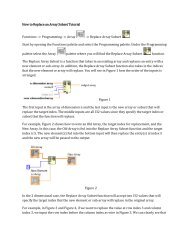
Figure 1: An example application with two modules.<br />
6<br />
INT_TO_LEDS
The example shown in Figure 1 is a simple application in which a hardware clock up-<br />
dates a s<strong>of</strong>tware counter, whose binary value is displayed on a set <strong>of</strong> LEDs. The <strong>TinyGALS</strong><br />
implementation <strong>of</strong> this application contains two modules: count <strong>and</strong> leds. Module<br />
count contains two components: COUNTER <strong>and</strong> CLOCK. Module leds contains a single<br />
component, INT_TO_LEDS.<br />
At runtime, the system framework initializes the COUNTER <strong>and</strong> INT_TO_LEDS com-<br />
ponents via the initialization ports (both named init) <strong>of</strong> modules count <strong>and</strong> leds,<br />
respectively. The runtime system then activates execution <strong>of</strong> the application via the sys-<br />
tem start port, which in this example begins at the count_start input port <strong>of</strong> module<br />
count.<br />
The hardware clock encapsulated by the CLOCK component periodically produces an<br />
event on the link between the CLOCK <strong>and</strong> COUNTER components via an interrupt service<br />
routine. The link represents a method call originating from the CLOCK component. The<br />
COUNTER component will respond to the call immediately by processing the event <strong>and</strong><br />
generating another event at the count_out output port <strong>of</strong> module count. The token<br />
(encapsulated data) corresponding to the event produced at count_out is stored in the<br />
input port to which the output port is connected, leds_in. Later, the runtime scheduler<br />
will activate the leds module in response to this event. This possibly delayed response<br />
corresponds to an asynchronous communication between modules <strong>and</strong> allows <strong>for</strong> decou-<br />
pling <strong>of</strong> the execution <strong>of</strong> modules. Finally, the INT_TO_LEDS component will process<br />
the event <strong>and</strong> display the value on the hardware LEDs.<br />
2.2 <strong>TinyGALS</strong> Language Constructs<br />
A <strong>TinyGALS</strong> program contains a single application composed <strong>of</strong> modules, which are in<br />
turn composed <strong>of</strong> components. In this section we describe the language constructs <strong>for</strong> each<br />
<strong>of</strong> these (components, modules, <strong>and</strong> application). Semantics are discussed in Section 2.3.<br />
7
2.2.1 <strong>TinyGALS</strong> Components<br />
Components are the most basic elements <strong>of</strong> a <strong>TinyGALS</strong> program. A <strong>TinyGALS</strong> compo-<br />
nent C is a 3-tuple:<br />
C = (VC,XC,IC), (1)<br />
where VC is a set <strong>of</strong> internal variables, XC is a set <strong>of</strong> external variables, <strong>and</strong> IC is a set<br />
<strong>of</strong> methods that constitute the interface <strong>of</strong> C. The internal variables carry the state <strong>of</strong> C<br />
from one invocation <strong>of</strong> an interface method <strong>of</strong> C to another. The external variables can<br />
be accessed by C through read <strong>and</strong> write operations. 2 The set <strong>of</strong> methods IC is further<br />
divided into two disjoint sets: ACCEPT SC <strong>and</strong> USESC. The methods in ACCEPT SC can<br />
be called by other components (these are the inputs <strong>of</strong> component C), while the methods<br />
in USESC are those needed by C <strong>and</strong> may possibly belong to other components (these are<br />
the outputs <strong>of</strong> component C). 3 Thus, a component is like an object in most object-oriented<br />
programming languages, but with explicit definition <strong>of</strong> the external variables <strong>and</strong> methods<br />
it uses. Syntactically, a component is defined in two parts – an interface definition <strong>and</strong> an<br />
implementation.<br />
Figure 2 shows a fragment <strong>of</strong> the code <strong>for</strong> the interface definition <strong>of</strong> the COUNTER<br />
component shown in Figure 1, while Figure 3 shows a fragment <strong>of</strong> the code <strong>for</strong> its imple-<br />
mentation. 4 In Figure 2, we see that the component has two ACCEPT S methods <strong>and</strong> one<br />
USES method. In Figure 3, we see that the component accesses an internal variable <strong>of</strong> type<br />
short named _counter. Using the tuple notation given in Equation 1, the COUNTER<br />
component can be defined as C = (VC = { counter},XC = /0,IC = {init, f ire, f ireOut}).<br />
2 External variables are implemented as TinyGUYS. See Section 2.4 <strong>for</strong> more in<strong>for</strong>mation.<br />
3 Using TinyOS conventions, ACCEPT SC is the set <strong>for</strong>med by the union <strong>of</strong> the TinyOS ACCEPTS <strong>and</strong><br />
HANDLES methods, <strong>and</strong> USESC is the set <strong>for</strong>med by the union <strong>of</strong> the TinyOS USES <strong>and</strong> SIGNALS methods.<br />
4 The syntax is similar to that <strong>of</strong> TinyOS.<br />
8
Component interface <strong>for</strong> COUNTER.<br />
COMPONENT COUNTER;<br />
ACCEPTS{<br />
char init(void);<br />
void fire(void);<br />
};<br />
USES{<br />
char fireOut(short value);<br />
};<br />
Figure 2: Fragment <strong>of</strong> code <strong>for</strong> interface definition <strong>of</strong> the COUNTER com-<br />
ponent shown in Figure 1.<br />
2.2.2 <strong>TinyGALS</strong> Modules<br />
Modules are the major building blocks <strong>of</strong> a <strong>TinyGALS</strong> program, encompassing one or more<br />
<strong>TinyGALS</strong> components. A <strong>TinyGALS</strong> module M is a 6-tuple:<br />
M = (COMPONENT SM,INITM,INPORT SM,OUT PORT SM,PARAMET ERSM,LINKSM),<br />
where COMPONENT SM is the set <strong>of</strong> components that <strong>for</strong>m the module; INITM is a list<br />
<strong>of</strong> initialization methods that belong to the components in COMPONENT SM; INPORT SM<br />
<strong>and</strong> OUT PORT SM are sets that specify the input ports <strong>and</strong> output ports <strong>of</strong> the module, re-<br />
spectively; PARAMET ERSM is a set <strong>of</strong> variables external to the components 5 ; <strong>and</strong> LINKSM<br />
specifies the relations among the interface methods <strong>of</strong> the components (IC in Equation 1)<br />
<strong>and</strong> the input <strong>and</strong> output ports <strong>of</strong> the module (INPORT SM <strong>and</strong> OUT PORT SM). Section<br />
2.3.3 describes links in more detail, including which configurations <strong>of</strong> components within<br />
a module are valid.<br />
Modules are different from components; INPORT SM <strong>and</strong> OUT PORT SM <strong>of</strong> a module<br />
M are not the same as ACCEPT SC <strong>and</strong> USESC <strong>of</strong> a component C. While ACCEPT SC<br />
5 Refer to in<strong>for</strong>mation on TinyGUYS in Section 2.4.<br />
9<br />
(2)
Component implementation <strong>for</strong> COUNTER.<br />
char init(){<br />
_counter = 0;<br />
return 1;<br />
}<br />
void fire(){<br />
_counter++;<br />
CALL_COMMAND(fireOut)(_counter);<br />
}<br />
Figure 3: Fragment <strong>of</strong> code <strong>for</strong> implementation <strong>of</strong> the COUNTER component<br />
shown in Figure 1. This provides the method bodes <strong>for</strong> the interface defined<br />
in Figure 2. The internal variable counter is <strong>of</strong> type short.<br />
<strong>and</strong> USESC refer to method calls <strong>and</strong> may be connected to ports in INPORT SM <strong>and</strong><br />
OUT PORT SM, INPORT SM <strong>and</strong> OUT PORT SM are not executable. Additionally, ports<br />
in INPORT SM that are connected to ports in OUT PORT SM contain an implicit queue (see<br />
Section 2.3.4).<br />
Initialization methods in INITM are slightly different from input ports in INPORT SM;<br />
they do not contain implicit queues since buffering <strong>of</strong> data is not needed during initializa-<br />
tion.<br />
Figure 4 gives the module definition code <strong>for</strong> the module count in the application<br />
shown in Figure 1. The definition states that module count contains two components,<br />
COUNTER <strong>and</strong> CLOCK. Note that component CLOCK accepts init() <strong>and</strong> uses fireOut();<br />
component COUNTER accepts init() <strong>and</strong> fire(), <strong>and</strong> uses fireOut() (see Figure<br />
2. The init section states that the init() method <strong>of</strong> component COUNTER belongs<br />
to the initialization list <strong>of</strong> the module. The connection section at the bottom <strong>of</strong> Figure 4<br />
declares that the fireOut() method <strong>of</strong> component CLOCK is mapped to the fire()<br />
method <strong>of</strong> component COUNTER; the fireOut() method <strong>of</strong> component COUNTER is<br />
mapped to the count_out outport <strong>of</strong> module count; <strong>and</strong> that the count_start in-<br />
port <strong>of</strong> module count is mapped to the init() method <strong>of</strong> component CLOCK.<br />
10
Module definition <strong>for</strong> count.<br />
include components{<br />
COUNTER;<br />
CLOCK;<br />
};<br />
init{<br />
COUNTER:init;<br />
};<br />
ports in{<br />
count_start;<br />
};<br />
ports out{<br />
count_out;<br />
};<br />
CLOCK:fireOut COUNTER:fire<br />
COUNTER:fireOut count_out<br />
count_start CLOCK:init<br />
Figure 4: The definition <strong>of</strong> the count module shown in Figure 1.<br />
Using the tuple notation given in Equation 2, the count module can be defined as<br />
M = (COMPONENT SM = {COUNT ER,CLOCK},<br />
INITM = [COUNT ER : init],<br />
INPORT SM = {count start},<br />
OUT PORT SM = {count out},<br />
PARAMET ERSM = /0,<br />
LINKSM = {(CLOCK : f ireOut,COUNT ER : f ire),<br />
(COUNT ER : f ireOut,count out),<br />
(count start,CLOCK : init)}).<br />
The code <strong>for</strong> the module leds is shown in Figure 5 <strong>for</strong> completeness. We will discuss<br />
the semantics <strong>of</strong> the execution <strong>of</strong> components within a module in more detail in Section<br />
2.3.3.<br />
11
Module definition <strong>for</strong> leds.<br />
include components{<br />
INT_TO_LEDS;<br />
};<br />
init{<br />
INT_TO_LEDS:init;<br />
};<br />
ports in{<br />
leds_in;<br />
};<br />
ports out{<br />
};<br />
leds_in INT_TO_LEDS:fire<br />
Figure 5: The definition <strong>of</strong> the leds module shown in Figure 1.<br />
2.2.3 <strong>TinyGALS</strong> Application<br />
At the top level <strong>of</strong> a <strong>TinyGALS</strong> program, modules are connected to <strong>for</strong>m a complete appli-<br />
cation. A <strong>TinyGALS</strong> application A is a 5-tuple:<br />
A = (MODULESA,GLOBALSA,VARMAPSA,CONNECT IONSA,STARTA), (3)<br />
where MODULESA is a list <strong>of</strong> modules in the application; GLOBALSA is a set <strong>of</strong> global<br />
variables; VARMAPSA is a set <strong>of</strong> mappings, each <strong>of</strong> which maps a global variable to a<br />
parameter (in PARAMET ERSMi ) <strong>of</strong> a module in MODULESA 6 ; CONNECT IONSA is a<br />
set <strong>of</strong> the connections between module output ports <strong>and</strong> input ports; STARTA is the name<br />
<strong>of</strong> an input port <strong>of</strong> exactly one module in the application. Section 2.3.4 describes which<br />
configurations <strong>of</strong> modules within an application are valid.<br />
Figure 6 shows the code <strong>for</strong> defining the application shown in Figure 1. The application<br />
contains two modules, count <strong>and</strong> leds. The output port count_out <strong>of</strong> module count<br />
is connected to the input port leds_in <strong>of</strong> module leds. The definition declares that the<br />
connection between count_out <strong>and</strong> leds_in has a FIFO queue <strong>of</strong> size 50. The last<br />
6 Refer to in<strong>for</strong>mation on TinyGUYS in Section 2.4.<br />
12
Application definition.<br />
include modules{<br />
count;<br />
leds;<br />
};<br />
count_out -> leds_in 50<br />
START@ count_start<br />
Figure 6: Definition <strong>of</strong> the application shown in Figure 1.<br />
line in the definition says that the system start port is count_start. Note that arguments<br />
(initial data) may be passed to the system start port on the same line.<br />
Using the tuple notation given in Equation 3, the example application can be defined as<br />
2.3 <strong>TinyGALS</strong> Semantics<br />
A = (MODULESA = [count,leds],<br />
GLOBALSA = /0,<br />
VARMAPSA = /0,<br />
CONNECT IONSA = [(count out,leds in)],<br />
STARTA = count start).<br />
In this section, we discuss the semantics <strong>of</strong> execution within a component, between com-<br />
ponents within a module, <strong>and</strong> between modules within an application. We also include a<br />
discussion <strong>of</strong> the conditions <strong>for</strong> well-<strong>for</strong>medness an application.<br />
2.3.1 Assumptions<br />
The <strong>TinyGALS</strong> architecture is intended <strong>for</strong> a plat<strong>for</strong>m with a single processor. All mem-<br />
ory is statically allocated; there is no dynamic memory allocation. A <strong>TinyGALS</strong> program<br />
13
uns in a single thread <strong>of</strong> execution (single stack), which may be interrupted by the hard-<br />
ware. Reentrant code can have multiple simultaneous, interleaved, or nested invocations<br />
which will not interfere with each other. In this section, we assume that interrupts are not<br />
reentrant, but that an interrupt is masked while servicing it (interleaved invocations are dis-<br />
abled). However, other interrupts may occur while servicing the interrupt. 7 There are no<br />
other sources <strong>of</strong> preemption other than hardware interrupts. When using components in<br />
which interrupts are enabled in the interrupt h<strong>and</strong>ler, we must take special care in placing<br />
constraints on what constitutes a valid configuration <strong>of</strong> components within a module in<br />
order to avoid unexpected reentrancy, which may lead to race conditions <strong>and</strong> other nonde-<br />
terminacy issues. We assume the existence <strong>of</strong> a clock, which is used to order events.<br />
2.3.2 <strong>TinyGALS</strong> Components<br />
There are three cases in which a component C may begin execution: (1) an interrupt from<br />
the hardware that C encapsulates, (2) an event arrives on the module input port linked to<br />
one <strong>of</strong> the interface methods <strong>of</strong> C, or (3) another component calls one <strong>of</strong> the interface meth-<br />
ods <strong>of</strong> C. In the first case, the component is a source component <strong>and</strong> when activated by a<br />
hardware interrupt, the corresponding interrupt service routine is run. Source components<br />
do not connect to any module input ports. In the second case, the component is a triggered<br />
component, <strong>and</strong> the event triggers the execution <strong>of</strong> the method (in ACCEPT SC) to which<br />
the input port is linked. Both source components <strong>and</strong> triggered components may call other<br />
components (via the methods in USESC), which results in the third case, where the com-<br />
ponent is a called component. Once activated, a component executes to completion. That<br />
7 The avr-gcc compiler <strong>for</strong> the Atmel AVR microcontroller on the MICA motes provides two macros <strong>for</strong><br />
writing user-defined interrupt service routines (locations specified in the interrupt vector table). The SIGNAL<br />
macro indicates that the specified function is a signal h<strong>and</strong>ler; interrupts are disabled inside the function. The<br />
INTERRUPT macro indicates that the specified function is an interrupt h<strong>and</strong>ler; interrupts are enabled inside<br />
the function. In the TinyOS v0.6.1 distribution, the following components use the INTERRUPT macro on the<br />
MICA motes: CLOCK, RF PROXIMITY, TIMESTAMP, LOGGER, UART (transmission only); the following<br />
components re-enable interrupts inside <strong>of</strong> the SIGNAL macro on the MICA motes: MIC <strong>and</strong> ADC.<br />
14
is, the interrupt service routine or method finishes.<br />
Reentrancy problems may arise if a component is both a source component <strong>and</strong> a trig-<br />
gered component. An event on a linked module input port may trigger the execution <strong>of</strong><br />
a component method. While the method runs, an interrupt may arrive, leading to pos-<br />
sible race conditions if the interrupt modifies internal variables <strong>of</strong> the same component.<br />
There<strong>for</strong>e, to improve the ease <strong>of</strong> analyzability <strong>of</strong> the system <strong>and</strong> eliminate the need to<br />
make components reentrant, source components must not also be triggered components,<br />
<strong>and</strong> vice versa. The same argument also applies to source components <strong>and</strong> called compo-<br />
nents. There<strong>for</strong>e, it is necessary that source components only have outputs (USESC) <strong>and</strong><br />
no inputs (ACCEPT SC). Additional rules <strong>for</strong> linking components together are detailed in<br />
the next section.<br />
In Figure 3, _counter is an internal variable. Each time the fire() method <strong>of</strong><br />
COUNTER is called, the component will call the fireOut() method with the value <strong>of</strong> the<br />
internal variable _counter as its argument. The CALL_COMMAND macro indicates that<br />
the fireOut() method will be called synchronously (we will explain this further in the<br />
next section). The component only needs to know the type signature <strong>of</strong> fireOut(), but<br />
it does not matter to which component the method is linked.<br />
2.3.3 <strong>TinyGALS</strong> Modules<br />
Flow <strong>of</strong> control between components within a <strong>TinyGALS</strong> module occurs on links. A link is<br />
a relation within a module M between a component method (in USESC) <strong>and</strong> another com-<br />
ponent method (in ACCEPT S ′ C ), between an input port <strong>of</strong> the module (in INPORT SM) <strong>and</strong><br />
a component method (in ACCEPT SC), or between a component method (in USESC) <strong>and</strong><br />
an output port <strong>of</strong> the module (in OUT PORT SM). Links represent synchronous communi-<br />
cation via method calls. When a component calls an external method (in USESC) through<br />
CALL_COMMAND, the flow <strong>of</strong> control in the module is immediately transferred to the callee<br />
component or port. The external method can return a value through CALL_COMMAND just<br />
15
as in a normal method call. 8 The graph <strong>of</strong> components <strong>and</strong> links between them is an ab-<br />
straction <strong>of</strong> the call graph <strong>of</strong> methods within a module, where the methods associated with<br />
a single component are grouped together.<br />
The execution <strong>of</strong> modules is controlled by a scheduler in the <strong>TinyGALS</strong> runtime sys-<br />
tem. There are two cases in which a module M may begin execution: (1) a triggered<br />
component is activated, or (2) a source component is activated. In the first case, the sched-<br />
uler activates the component attached to an input port <strong>of</strong> M in response to an event sent<br />
to M by another module. In the second case, M contains a source component which has<br />
received a hardware interrupt. Notice that in this case, M may be interrupting the execution<br />
<strong>of</strong> another module. A module is considered to be finished executing when the components<br />
inside <strong>of</strong> it have finished executing <strong>and</strong> control has returned to the scheduler.<br />
As discussed in the previous section, preemption <strong>of</strong> the normal thread <strong>of</strong> execution by<br />
an interrupt may lead to reentrancy problems. There<strong>for</strong>e, we must place some restrictions<br />
on what configurations <strong>of</strong> components within a module are allowed.<br />
Cycles within modules (between components) are not allowed, otherwise reentrant<br />
components are required. 9 There<strong>for</strong>e, any valid configurations <strong>of</strong> components within a<br />
module can be modeled as a directed acyclic graph (DAG). A source DAG in a module<br />
M is <strong>for</strong>med by starting with a source component C in M <strong>and</strong> following all <strong>for</strong>ward links<br />
between C <strong>and</strong> other components in M. Figure 7 shows an example <strong>of</strong> a source DAG in-<br />
side <strong>of</strong> a module. A triggered DAG in a module M is <strong>for</strong>med by starting with a triggered<br />
component C in M <strong>and</strong> following all <strong>for</strong>ward links between C <strong>and</strong> other components in M.<br />
Figure 8 shows an example <strong>of</strong> a triggered DAG inside <strong>of</strong> a module.<br />
In general, within a module, source DAGs <strong>and</strong> triggered DAGs must be not be con-<br />
nected. In Figure 9, the source DAG (C1, C3) is connected to the triggered DAG (C2,<br />
C3). Suppose C2 is triggered by an event on the input port <strong>of</strong> M <strong>and</strong> calls C3. Reentrancy<br />
live.<br />
8 In TinyOS, the return value indicates whether the comm<strong>and</strong> completed successfully or not.<br />
9 Recursion within components is allowed. However, the recursion must be bounded <strong>for</strong> the system to be<br />
16
Module M<br />
C1 C2<br />
Figure 7: A source DAG inside Module M. This DAG is activated by a hardware interrupt.<br />
Module M<br />
C1 C2<br />
Figure 8: A triggered DAG inside Module M. This DAG is activated by the arrival <strong>of</strong> an<br />
event at the module input port.<br />
problems may occur if an interrupt causes C1 to preempt C3.<br />
Module M<br />
C1<br />
C2<br />
Figure 9: Not allowed; source DAG connected to triggered DAG.<br />
If all interrupts are masked during interrupt h<strong>and</strong>ling (interrupts are disabled), then we<br />
need not place any additional restrictions on source DAGs. However, if interrupts are not<br />
masked (interrupts are enabled), then a source DAG must not be connected to any other<br />
source DAG within the same module.<br />
Triggered DAGs can be connected to other triggered DAGs, since with a single thread<br />
<strong>of</strong> execution, it is not possible <strong>for</strong> a triggered component to preempt a component in any<br />
other triggered DAG. Recall that once triggered, the components in a triggered DAG will<br />
execute to completion. We must also place restrictions on what connections are allowed<br />
between component methods <strong>and</strong> module ports, since some configurations may lead to<br />
17<br />
C3
nondeterministic component firing order.<br />
Let us first assume that both module input ports <strong>and</strong> module output ports are totally<br />
ordered (we assign the order to be the same as the order specified in the ports in <strong>and</strong><br />
ports out sections <strong>of</strong> the module definition file). However, we assume that compo-<br />
nents are not ordered. As discussed earlier, the configuration <strong>of</strong> components inside <strong>of</strong> a<br />
module must not contain cycles <strong>and</strong> must follow the rules above regarding source <strong>and</strong> trig-<br />
gered DAGs. Then module input ports may either be associated with one method <strong>of</strong> a<br />
single component C (in ACCEPT SC) or with one or more module output ports. Likewise,<br />
outgoing component methods (USES) may be associated with either one method <strong>of</strong> a sin-<br />
gle component C (in ACCEPT SC) or with one or more module output ports. 10 Incoming<br />
component methods (ACCEPT S) may be associated with any number or combination <strong>of</strong><br />
component methods (USES) <strong>and</strong> module input ports, but they may not be associated with<br />
module output ports. Likewise, module output ports may be associated with any number<br />
or combination <strong>of</strong> outgoing component methods (USES) <strong>and</strong> module output ports.<br />
If neither module input ports nor module output ports are ordered, then module input<br />
ports <strong>and</strong> outgoing component methods may only be associated with either a single method<br />
or with a single output port.<br />
In Figure 4, the connection section at the bottom <strong>of</strong> the module definition declares<br />
that whenever the count_start input port is triggered (which will be explained in<br />
the next section), the init() method <strong>of</strong> CLOCK will be called; whenever CLOCK calls<br />
fireOut(), the method fire() <strong>of</strong> COUNTER will be called; <strong>and</strong> whenever COUNTER<br />
calls fireOut(), an event will be produced at the count_out output port.<br />
10 In the existing TinyOS constructs, one caller (outgoing component method) can have multiple callees.<br />
The interpretation is that when the caller calls, all the callees will be called in a possibly non-deterministic<br />
order. One <strong>of</strong> the callee’s return values will be returned to the caller. Although multiple callees are not part<br />
<strong>of</strong> the <strong>TinyGALS</strong> semantics, it is supported by our s<strong>of</strong>tware tools to be compatible with TinyOS.<br />
18
2.3.4 <strong>TinyGALS</strong> Application<br />
The execution <strong>of</strong> a <strong>TinyGALS</strong> system begins with initialization <strong>of</strong> all methods specified in<br />
INITMi <strong>for</strong> all modules Mi. The order in which modules are initialized is the same as the<br />
order in which they are listed in the application configuration file (e.g., as in Figure 6). The<br />
order in which methods are initialized <strong>for</strong> a single module is the same as the order in which<br />
they are listed in the module configuration file (e.g., as in Figure 4 or Figure 5).<br />
Execution <strong>of</strong> the application begins at the system start port (STARTA), which is a mod-<br />
ule input port declared in the START@ section <strong>of</strong> the application configuration file. After<br />
module initialization, the <strong>TinyGALS</strong> runtime system triggers the system start port exactly<br />
once. Additional start triggers are not used since there is a single thread <strong>of</strong> execution. If<br />
initial arguments were declared in the application configuration file, these are passed to<br />
the component input method that is linked to the system start port at this time. For ex-<br />
ample, in Figure 6, the application starts when the runtime system triggers the input port<br />
count_start <strong>of</strong> module count. The components in the triggered DAG <strong>of</strong> the starting<br />
module execute to completion <strong>and</strong> may generate one or more events at the output port(s)<br />
<strong>of</strong> the module, which we discuss next. During execution, interrupts may occur <strong>and</strong> pre-<br />
empt the normal thread <strong>of</strong> execution. However, control will eventually return to the normal<br />
thread <strong>of</strong> execution.<br />
During application execution, communication between module ports occurs asynchro-<br />
nously via FIFO queues. When a component within a module calls a method that is linked<br />
to an output port, the arguments <strong>of</strong> the call are converted into tokens. For each input port<br />
connected to the output port, a copy <strong>of</strong> the token is placed in its FIFO queue. Later, a<br />
scheduler in the <strong>TinyGALS</strong> runtime system will remove a token from the FIFO queue <strong>and</strong><br />
call the method that is linked to the input port with the contents <strong>of</strong> the token as its argu-<br />
ments. The queue separates the flow <strong>of</strong> control between modules; the call to the output port<br />
will return immediately, <strong>and</strong> the component within the module can proceed. Communica-<br />
tion between modules is also possible without the transfer <strong>of</strong> data. In this case, an empty<br />
message (token) transferred between ports acts as a trigger <strong>for</strong> activation <strong>of</strong> the receiving<br />
19
module. Tokens are placed in input port queues atomically, so other source components<br />
cannot interrupt this operation. Note that since each input port <strong>of</strong> a module M is linked to a<br />
component method, each token that arrives on any input port <strong>of</strong> M corresponds to a future<br />
invocation <strong>of</strong> the component(s) in M. When the system is not responding to interrupts or<br />
events on input ports, the system does nothing (i.e., sleeps).<br />
The <strong>TinyGALS</strong> semantics do not define exactly when the input port is triggered. We<br />
discuss the ramifications <strong>of</strong> token generation order on the determinacy <strong>of</strong> the system in<br />
Section 3. Our current implementation processes the tokens in the order that they are<br />
generated as defined by the hardware clock. Tokens generated at the same logical time<br />
are ordered according to the global ordering <strong>of</strong> module input ports, which we discuss next.<br />
The runtime system maintains a global event queue which keeps track <strong>of</strong> the tokens in<br />
all module input port queues in the system. Currently, the runtime system activates the<br />
modules corresponding to the tokens in the global event queue using FIFO scheduling.<br />
More sophisticated scheduling algorithms can be added, such as ones that take care <strong>of</strong><br />
timing <strong>and</strong> energy concerns.<br />
In the previous section, we discussed limitations on the configuration <strong>of</strong> links between<br />
components within a module. Connections between modules are much less restrictive.<br />
Cycles are allowed between modules. This does not lead to reentrancy problems because<br />
the queue on a module input port acts as a delay in the loop. Module output ports may be<br />
connected to one or more module input ports, <strong>and</strong> module input ports may be connected<br />
to one or more module output ports. The single-output-multiple-input connection acts as<br />
a <strong>for</strong>k. For example, in Figure 10, every token produced by A_out will be duplicated<br />
<strong>and</strong> trigger both B_in <strong>and</strong> C_in. Tokens that are produced at the same “time”, as in the<br />
previous example, are processed with respect to the global input port ordering. Input ports<br />
are first ordered by module order, as they appear in the application configuration file, then in<br />
the order in which they are declared in the module configuration file. The multiple-output-<br />
single-input connection has a merge semantics, such that tokens from multiple sources are<br />
merged into a single stream in the order that the tokens are produced. This type <strong>of</strong> merge<br />
does not introduce any additional sources <strong>of</strong> nondeterminacy. See Section 3 <strong>for</strong> a discussion<br />
20
<strong>of</strong> interrupts <strong>and</strong> their effect on the order <strong>of</strong> events in the global event queue.<br />
2.4 TinyGUYS<br />
Module A<br />
A_out<br />
Module B<br />
B_in<br />
Module C<br />
C_in<br />
Figure 10: Single output multiple input connection.<br />
The <strong>TinyGALS</strong> programming model has the advantage that the modules become decoupled<br />
through message passing <strong>and</strong> are easier to develop independently. However, each mes-<br />
sage passed will trigger the scheduler <strong>and</strong> activate a receiving module, which may quickly<br />
become inefficient if there is global state which must be updated frequently. TinyGUYS<br />
(Guarded Yet Synchronous) is a mechanism <strong>for</strong> sharing global state, allowing quick access<br />
but with protected modification <strong>of</strong> the data.<br />
One must be very careful when implementing global data spaces in concurrent pro-<br />
grams. Many modules may access the same global variables at the same time. It is possible<br />
that while one module is reading the variables, an interrupt may occur <strong>and</strong> preempt the<br />
reading. The interrupt service routine may modify the global variables. When the module<br />
resumes reading the remaining variables after h<strong>and</strong>ling the interrupt, it may see an inconsis-<br />
tent state. In the TinyGUYS mechanism, global variables are guarded. Modules may read<br />
the global variables synchronously (i.e., without delay). However, writes to the variable<br />
are asynchronous in the sense that all writes are delayed. A write to a TinyGUYS global<br />
variable is actually a write to a copy <strong>of</strong> the global variable. One can think <strong>of</strong> this as a write<br />
buffer <strong>of</strong> size one. Because there is only one buffer per global variable, the last module to<br />
write to the variable “wins”, i.e., the last value written will be the new value <strong>of</strong> the global<br />
21
Application def.<br />
include modules{<br />
A;<br />
B;<br />
};<br />
globals{<br />
statevar;<br />
};<br />
statevar A_param<br />
statevar B_param<br />
...<br />
// Module def. <strong>for</strong> A<br />
include components{<br />
A1;<br />
};<br />
parameters{<br />
int A_param;<br />
};<br />
...<br />
Figure 11: Defining <strong>and</strong> accessing TinyGUYS variables.<br />
// Component impl. <strong>for</strong> A1<br />
...<br />
void fire() {<br />
...<br />
int a;<br />
a=PARAMETER_GET(A_param);<br />
a++;<br />
PARAMETER_PUT(A_param)(a);<br />
...<br />
};<br />
variable. TinyGUYS variables are updated atomically by the scheduler only when it is safe<br />
(e.g., after one module finishes <strong>and</strong> be<strong>for</strong>e the scheduler triggers the next module). One<br />
can think <strong>of</strong> this as a way <strong>of</strong> <strong>for</strong>malizing race conditions. We discuss how to eliminate race<br />
conditions in Section 3.1.<br />
TinyGUYS have global names (GLOBALSA) that are mapped to the parameters (PARAMET ERSM)<br />
<strong>of</strong> each module M. If a component C uses a parameter, it must declare it as an external<br />
variable (XC). Figure 11 shows some sample code <strong>for</strong> defining <strong>and</strong> accessing TinyGUYS<br />
variables. The left-h<strong>and</strong> column <strong>of</strong> Figure 11 shows an application definition, which con-<br />
tains a list <strong>of</strong> global variable names, as well as a list <strong>of</strong> mappings from global names to local<br />
names. These local variables must be defined as parameters <strong>of</strong> the modules; this is shown<br />
in the center column <strong>of</strong> Figure 11. Local variables can be accessed within a component<br />
by using special constructs, PARAMETER_GET <strong>and</strong> PARAMETER_PUT, as shown in the<br />
right-h<strong>and</strong> column <strong>of</strong> Figure 11. This style <strong>of</strong> declaration, in which the types <strong>of</strong> the global<br />
variables must be declared at the module level, is slightly awkward. This means that the<br />
types must be declared <strong>for</strong> each module that uses the global variables. It also increases the<br />
fragility <strong>of</strong> the component code, since the components do not know the types <strong>of</strong> the global<br />
variables. In the future, we plan to improve this mechanism to use scoping, perhaps in a<br />
way similar to scoped parameters in Ptolemy II [11]. We could also use the Ptolemy II type<br />
system to improve the way in which types must be declared in <strong>TinyGALS</strong>.<br />
22
3 Discussion<br />
In this section we discuss issues related to determinacy <strong>of</strong> a <strong>TinyGALS</strong> program. We begin<br />
with definitions <strong>for</strong> a <strong>TinyGALS</strong> system, system state (including quiescent system state<br />
<strong>and</strong> active system state), module iteration (in response to an interrupt <strong>and</strong> in response to<br />
an event), <strong>and</strong> system execution. We also review the conditions <strong>for</strong> well-<strong>for</strong>medness <strong>of</strong> a<br />
<strong>TinyGALS</strong> system.<br />
Definition 1 (System). A system consists <strong>of</strong> an application <strong>and</strong> a global event queue. Recall<br />
that an application is defined as:<br />
A = (MODULESA,GLOBALSA,VARMAPSA,CONNECT IONSA,STARTA).<br />
Recall that the inport associated with a connection between modules has a FIFO queue<br />
<strong>for</strong> ordering <strong>and</strong> storing events destined <strong>for</strong> the inport. The global event queue provides<br />
an ordering <strong>for</strong> tokens in all inport queues. Whenever a token is stored in an inport queue,<br />
a representation <strong>of</strong> this event (implemented as an identifier <strong>for</strong> the inport queue) is also<br />
inserted into the global event queue. Thus, events that are produced earlier in time appear<br />
in the global event queue be<strong>for</strong>e events that are produced later in time (with respect to the<br />
system clock). Events that are produced at the same time (e.g., as in Figures 12 or 10) are<br />
ordered first by order <strong>of</strong> appearance in the application modules list (MODULESA), then<br />
by order <strong>of</strong> appearance in the modules inports list (INPORT S ′ M , which is an ordered list<br />
created from the modules inports set INPORT SM).<br />
Module M<br />
(event,t0)<br />
(event,t0)<br />
Figure 12: Two events are produced at the same time.<br />
Definition 2 (System state). The system state consists <strong>of</strong> four main items:<br />
23
1. The values <strong>of</strong> all internal variables <strong>of</strong> all components (VCi ).<br />
2. The contents <strong>of</strong> the global event queue.<br />
3. The contents <strong>of</strong> all <strong>of</strong> the queues associated with module input ports in the applica-<br />
tion.<br />
4. The values <strong>of</strong> all TinyGUYS (GLOBALSA).<br />
Recall that the global event queue contains the events in the system, but the module<br />
input ports contain the data associated with the event, encapsulated as a token.<br />
There are two distinct kinds <strong>of</strong> system state: quiescent <strong>and</strong> active.<br />
Definition 2.1 (quiescent system state). A system state is quiescent if there are no events<br />
in the global event queue, <strong>and</strong> hence, no events in any <strong>of</strong> the module inport queues in the<br />
system.<br />
Definition 2.2 (active system state). A system state is active if there is at least one event<br />
in the global event queue, <strong>and</strong> hence, at least one event in the queue <strong>of</strong> at least one module<br />
inport.<br />
Note that a <strong>TinyGALS</strong> system actually starts in an active system state, since execution<br />
begins by triggering a module input port.<br />
Execution <strong>of</strong> the system can be partitioned into module iterations based on component<br />
execution.<br />
Definition 3 (Component execution). A source component is activated when the hardware<br />
it encapsulates receives an interrupt. A triggered or called component C is activated when<br />
one <strong>of</strong> its methods (in ACCEPT SC) is called. Component execution is the execution <strong>of</strong> the<br />
code in the body <strong>of</strong> the interrupt service routine or method through which the component<br />
has been activated.<br />
24
Note that the code executed upon component activation may call other methods in the<br />
same component or in a linked component. Component execution also includes execution<br />
<strong>of</strong> all external code until control returns <strong>and</strong> execution <strong>of</strong> the code body has completed.<br />
Definition 4 (Module iteration). An iteration <strong>of</strong> a module M is the execution <strong>of</strong> a subset<br />
<strong>of</strong> the components inside <strong>of</strong> M in response to either an interrupt or an event.<br />
We define these two types <strong>of</strong> module iterations in more detail, including what we mean<br />
by “subset <strong>of</strong> components”.<br />
Definition 4.1 (Module iteration in response to an interrupt). Suppose module M is<br />
iterated in response to interrupt I. Let C be the component corresponding to interrupt I.<br />
Recall from Section 2.3.2 that C there<strong>for</strong>e must be a source component. Create a source<br />
DAG D by starting with C <strong>and</strong> following all <strong>for</strong>ward links between C <strong>and</strong> other components<br />
in M. Iteration <strong>of</strong> the module consists <strong>of</strong> the execution <strong>of</strong> the components in D beginning<br />
with C. Note that iteration <strong>of</strong> the module may cause it to produce one or more events on its<br />
output port(s).<br />
Definition 4.2 (Module iteration in response to an event). Suppose module M is iterated<br />
in response to an event E stored at the head <strong>of</strong> one <strong>of</strong> its inport queues, Q. Let C be<br />
the component corresponding to Q. Recall from Section 2.3.2 that C there<strong>for</strong>e must be<br />
a triggered component. Create a triggered DAG D by starting with C <strong>and</strong> following all<br />
<strong>for</strong>ward links between C <strong>and</strong> other components in M. Iteration <strong>of</strong> the module consists <strong>of</strong><br />
the execution <strong>of</strong> the components in D beginning with C. As with the interrupt case, iteration<br />
<strong>of</strong> the module may cause it to produce one or more events on its output port(s).<br />
We can now discuss how to choose the module iteration order.<br />
Definition 5 (System execution). Given a system state <strong>and</strong> zero or more interrupts, system<br />
execution is the iteration <strong>of</strong> modules until the system reaches a quiescent state. The order<br />
in which modules are executed is the same as the order <strong>of</strong> events in the global event queue.<br />
25
Conditions <strong>for</strong> well-<strong>for</strong>medness Here, we summarize the conditions <strong>for</strong> well-<strong>for</strong>medness<br />
<strong>of</strong> a system, as discussed in Section 2.3.<br />
1. Source (interrupt-driven) components must only have outputs, they may not have<br />
inputs. In other words, source components may not also be triggered components<br />
(triggered by an event on a module input port) nor called components (called by<br />
other components).<br />
2. Cycles among components within a module are not allowed, but loops around mod-<br />
ules are allowed.<br />
3. Within a module, component source DAGs <strong>and</strong> triggered DAGs must be discon-<br />
nected.<br />
4. Within a module, component source DAGs must not be connected to other source<br />
DAGs, but triggered DAGs may be connected to other triggered DAGs. We assume<br />
that an interrupt whose h<strong>and</strong>ler is running is masked, but other interrupts are not<br />
masked.<br />
5. Within a module, outgoing component methods may be associated with either one<br />
method <strong>of</strong> another component, or with one or more module output ports.<br />
6. Within a module, module input ports may be associated with either one method <strong>of</strong> a<br />
single component, or with one or more module output ports.<br />
3.1 Determinacy<br />
Given the definitions in the previous section, we first discuss determinism <strong>of</strong> a <strong>TinyGALS</strong><br />
system in the case <strong>of</strong> a single interrupt when in a quiescent state. We then discuss deter-<br />
minism <strong>for</strong> one or more interrupts during module iteration in the cases where there are no<br />
global variables <strong>and</strong> when there are global variables.<br />
26
In our intuitive notion <strong>of</strong> determinacy, given an initial quiescent system state <strong>and</strong> a set<br />
<strong>of</strong> interrupts that occur at known times, the system will always produce the same outputs<br />
<strong>and</strong> end up in the same state after responding to the interrupts.<br />
Theorem 1 (Determinacy). A system is determinate if <strong>for</strong> each quiescent state <strong>and</strong> a single<br />
interrupt, there is only one system execution path.<br />
interrupt I<br />
q0<br />
quiescent<br />
state<br />
m0 m1 m2<br />
a0,0<br />
a module iteration<br />
a0,1<br />
active states<br />
...<br />
a0,n−1<br />
Figure 13: Single interrupt.<br />
mn<br />
q1<br />
quiescent<br />
state<br />
Recall that a <strong>TinyGALS</strong> system starts in an active system state. The application start<br />
port is a module input port which is in turn linked to a component C inside the module.<br />
The component C is a triggered component, which is part <strong>of</strong> a DAG. Components in this<br />
triggered DAG execute <strong>and</strong> may generate events at the output port(s) <strong>of</strong> the module. System<br />
execution proceeds until the system reaches a quiescent state. From this quiescent state, we<br />
can analyze the determinacy <strong>of</strong> a <strong>TinyGALS</strong> system.<br />
Figure 13 depicts iteration <strong>of</strong> a <strong>TinyGALS</strong> system between two quiescent states due<br />
to activation by an interrupt I0. A <strong>TinyGALS</strong> system is determinate, since the system<br />
execution path is the order in which the modules are iterated, <strong>and</strong> in each <strong>of</strong> the steps<br />
m0,m1,...,mn, the module selected is determined by the order <strong>of</strong> events in the global event<br />
queue.<br />
What if we consider the case in which we have one or more interrupts during a module<br />
iteration, that is, between quiescent states, as is usually true in an event-driven system?<br />
27
Determinacy <strong>of</strong> a system without global variables. We will first examine the case<br />
where there are no TinyGUYS global variables.<br />
Let us consider a module M that contains a component C which produces events on<br />
the outports <strong>of</strong> M. Suppose the iteration <strong>of</strong> module M is interrupted one or more times.<br />
Since source DAGs must not be connected to triggered DAGs, the interrupt(s) cannot cause<br />
the production <strong>of</strong> events on outports <strong>of</strong> M that would be used in the case <strong>of</strong> a normal<br />
uninterrupted iteration. However, the interrupt(s) may cause insertion <strong>of</strong> events into other<br />
module inport queues, <strong>and</strong> hence insertions into the global event queue. Depending on the<br />
relative timing between the interrupts <strong>and</strong> the production <strong>of</strong> events by C at outports <strong>of</strong> M,<br />
the order <strong>of</strong> events in the global event queue may not be consistent between multiple runs<br />
<strong>of</strong> the system if the same interrupts occur during the same module iteration, but at slightly<br />
different times. This is a source <strong>of</strong> non-determinacy.<br />
If we wish to reduce the non-determinacy in the system, a partial solution is to delay<br />
producing outputs from the module being iterated until the end <strong>of</strong> its iteration. If we know<br />
the order <strong>of</strong> interrupts, then we can predict the state <strong>of</strong> the system after a single module<br />
iteration even if it is interrupted one or more times. Figure 14 shows a system execution in<br />
which a single module iteration is interrupted by multiple interrupts. In our notation, a i j,k<br />
refers to an active system state after an interrupt Ii starting from quiescent state q j <strong>and</strong> after<br />
module iteration mk. In Figure 14, the superscript in ax j,k is a shorth<strong>and</strong> <strong>for</strong> the sequence <strong>of</strong><br />
interrupts I0,I1,I2,...,In.<br />
I0<br />
q0<br />
I1I2 In<br />
...<br />
a x 0,0<br />
a x 0,1<br />
...<br />
a x 0,n<br />
Figure 14: One or more interrupts where modules have delayed output.<br />
In order to determine the value <strong>of</strong> active system state ax j,k , we can “add” the combined<br />
system states. Suppose active state a1 0,0 would be the next state after an iteration <strong>of</strong> the<br />
28<br />
q1
module corresponding to interrupt I1 from quiescent state q0, <strong>and</strong> that active state a 2 0,0<br />
would be the next state after an iteration <strong>of</strong> the module corresponding to interrupt I2 from<br />
q0. This is illustrated in Figure 15.<br />
Ii<br />
q0<br />
a i 0,0<br />
Figure 15: Active system state after one interrupt.<br />
We assume that the h<strong>and</strong>lers <strong>for</strong> interrupts I1,I2,...,In execute quickly enough such that<br />
they are not interleaved (e.g., I2 does not interrupt the h<strong>and</strong>ling <strong>of</strong> I1). Then the system state<br />
be<strong>for</strong>e the iteration <strong>of</strong> module M in response to interrupt I0 has completed but after inter-<br />
rupts I1 <strong>and</strong> I2 would be a1 0,0 +a20,0 , where the value <strong>of</strong> this expression is the system state in<br />
which the new events produced in active system state a2 0,0 are inserted (or “appended”) into<br />
the corresponding module inport queues in active system state a1 0,0 . We can extend this to<br />
any finite number <strong>of</strong> interrupts, In, as shown in Figure 16. It is necessary that the number<br />
<strong>of</strong> interrupts be finite <strong>for</strong> liveness <strong>of</strong> the system. From the per<strong>for</strong>mance perspective, it is<br />
also necessary that interrupt h<strong>and</strong>ling be fast enough that the h<strong>and</strong>ling <strong>of</strong> the first interrupt<br />
I0 completes in a reasonable length <strong>of</strong> time. If the interrupts are interleaved, we must add<br />
the system state (append module inport queue contents) in the order in which the interrupt<br />
h<strong>and</strong>lers finish.<br />
Another solution, which leads to greater predictability in the system, is to preschedule<br />
module iterations. That is, if an interrupt occurs, a sequence <strong>of</strong> module iterations is sched-<br />
uled <strong>and</strong> executed, during which interrupts are masked. One can also queue interrupts in<br />
order to eliminate preemption. Then, system execution is deterministic <strong>for</strong> a fixed sequence<br />
<strong>of</strong> interrupts. However, both <strong>of</strong> these approaches reduces the reactiveness <strong>of</strong> the system.<br />
Determinacy <strong>of</strong> a system with global variables. Let us now discuss system determinacy<br />
in the case where there are TinyGUYS global variables (GLOBALSA).<br />
29
I0<br />
q0<br />
I1 I2 In<br />
a 1 0,0<br />
a 1 0,0 + a2 0,0<br />
...<br />
a 1 0,0 + a2 0,0 + ... + an 0,0<br />
a 1 0,0 + a2 0,0 + ... + an 0,0 + a0 0,0<br />
Figure 16: Active system state determined by adding the active system state after one non-<br />
interleaved interrupt.<br />
Suppose that module M writes to a global variable. Also suppose that the iteration<br />
<strong>of</strong> module M is interrupted, <strong>and</strong> a component in the interrupting source DAG writes to the<br />
same global variable. Then without timing in<strong>for</strong>mation, we cannot predict the final value <strong>of</strong><br />
the global variable at the end <strong>of</strong> the iteration. (Note that when read, a global variable always<br />
contains the same value throughout an entire module iteration). As currently defined, the<br />
state <strong>of</strong> the system after the iteration <strong>of</strong> module M is interrupted by one or more interrupts is<br />
highly dependent on the time at which the components in M write to the global variable(s).<br />
There are several possible alternatives eliminate this source <strong>of</strong> nondeterminacy.<br />
Solution 1 Allow only one writer <strong>for</strong> each TinyGUYS global variable.<br />
Solution 2 Allow multiple writers, but only if they can never write at the same time. That<br />
is, if a component in a triggered DAG writes to a TinyGUYS global variable,<br />
no component in any source DAG can be a writer (but components in other trig-<br />
gered DAGs are allowed since they cannot execute at the same time). Likewise,<br />
if a component in a source DAG writes to a TinyGUYS global variable then no<br />
component in any triggered DAG can be a writer. Components in other source<br />
DAGs are only allowed to write if all interrupts are masked.<br />
Solution 3 Delay writes to a TinyGUYS global variable by an iterating module until the<br />
end <strong>of</strong> the iteration.<br />
30
Solution 4 Prioritize writes such that once a high priority writer has written to the TinyGUYS<br />
global variables, lower priority writes will be lost.<br />
Summary We have just discussed system determinacy in the case <strong>of</strong> a single interrupt<br />
<strong>and</strong> determination <strong>of</strong> system state when a module iteration is interrupted by one or more<br />
interrupts.<br />
If we do not use one <strong>of</strong> the solutions presented, the system state at the completion <strong>of</strong> an<br />
interrupted module iteration depends on the timing <strong>of</strong> the interrupts. Without prescheduling<br />
module iterations, the next quiescent system state after an interrupted module iteration is<br />
also highly dependent on module execution times <strong>and</strong> the timing <strong>of</strong> the interrupts.<br />
However, event-driven systems are usually designed to be reactive. In these cases,<br />
interrupts should be considered as high priority events which should affect the system state<br />
as soon as possible.<br />
4 Code Generation<br />
Given the highly structured architecture <strong>of</strong> the <strong>TinyGALS</strong> model, code <strong>for</strong> scheduling <strong>and</strong><br />
event h<strong>and</strong>ling can be automatically generated to release s<strong>of</strong>tware developers from writing<br />
error-prone concurrency control code. We have created a set <strong>of</strong> code generation tools <strong>for</strong><br />
the MICA motes that, given the definitions <strong>for</strong> the components, modules, <strong>and</strong> application,<br />
will automatically generate all the code necessary <strong>for</strong> (1) component links <strong>and</strong> module<br />
connections, (2) system initialization <strong>and</strong> start <strong>of</strong> execution, (3) communication between<br />
modules, <strong>and</strong> (4) TinyGUYS global variable reads <strong>and</strong> writes.<br />
In this section, we also give an overview <strong>of</strong> the implementation <strong>of</strong> the <strong>TinyGALS</strong> sched-<br />
uler <strong>and</strong> how it interacts with TinyOS, as well as data on the memory usage <strong>of</strong> <strong>TinyGALS</strong>.<br />
31
app_init()<br />
app_start()<br />
statevar_PARAM_PUT() statevar_PARAM_GET()<br />
init<br />
A_in<br />
Module A<br />
init()<br />
fire()<br />
ACOMP1<br />
statevar<br />
A_param<br />
ACOMP2<br />
fireOut()<br />
data<br />
structures<br />
A_out<br />
A_out() B_in_put()<br />
data<br />
structures<br />
B_in<br />
BCOMP1_FIRE()<br />
Figure 17: A code generation example.<br />
Module B<br />
fire()<br />
Scheduler<br />
Event<br />
Queue<br />
BCOMP1<br />
Throughout this section, we will use the example system illustrated in Figure 17. This<br />
system is composed <strong>of</strong> two modules: A <strong>and</strong> B. Module A contains two components, ACOMP1<br />
<strong>and</strong> ACOMP2. Component ACOMP2 accesses a parameter <strong>and</strong> has a definition similar to<br />
the definition <strong>of</strong> component A1 given in Figure 11. Module B contains a single component<br />
named BCOMP1, which has a function called fire() that is connected to the input port<br />
B_in <strong>of</strong> module B. Figure 17 also summarizes all functions <strong>and</strong> data structures generated<br />
by the code generator.<br />
4.1 Links <strong>and</strong> Connections<br />
The code generator will generate a set <strong>of</strong> aliases which create the maps <strong>for</strong> the links between<br />
components, as well as the maps <strong>for</strong> the connections between modules. In the example, an<br />
alias will be generated <strong>for</strong> the link between ACOMP1 <strong>and</strong> ACOMP2, <strong>and</strong> <strong>for</strong> the connection<br />
between modules A <strong>and</strong> B.<br />
32
4.2 System Initialization <strong>and</strong> Start <strong>of</strong> Execution<br />
The code generator will create a system-level initialization function called app_init(),<br />
which contains calls to the INIT methods <strong>of</strong> each module in the system. The order <strong>of</strong><br />
modules listed in the system definition determines the order in which the INIT methods will<br />
be called. The app_init() function is one <strong>of</strong> the first functions called by the <strong>TinyGALS</strong><br />
runtime scheduler be<strong>for</strong>e executing the application. In Figure 17, only module A contains<br />
an initialization list. There<strong>for</strong>e, the generated app_init() function will only contain a<br />
call to ACOMP1:init.<br />
The code generator will also create the application start function, app_start(). This<br />
function will trigger the input port <strong>of</strong> the module defined as the system start port. In the<br />
example, app_start() will contain a trigger <strong>for</strong> the input port A_in <strong>of</strong> module A.<br />
4.3 Communication<br />
The code generator will automatically generate a set <strong>of</strong> scheduler data structures <strong>and</strong> func-<br />
tions <strong>for</strong> each connection between modules.<br />
For each input port <strong>of</strong> a module, the code generator will generate a queue <strong>of</strong> length n,<br />
where n is specified in the application definition file. The width <strong>of</strong> the queue depends on the<br />
number <strong>of</strong> arguments to the method that is connected to the port. If there are no arguments,<br />
then as an optimization, no queue is generated <strong>for</strong> the port (but space is still reserved <strong>for</strong><br />
events in the scheduler event queue). A pointer <strong>and</strong> a counter are also generated <strong>for</strong> each<br />
input port to keep track <strong>of</strong> the location <strong>and</strong> number <strong>of</strong> tokens in the queue. For the example<br />
in Figure 17, the definition <strong>of</strong> port B_in will result in the generation <strong>of</strong> a port queue called<br />
B_in_0[] (assuming port B_in is linked to a function with a single argument), as well<br />
as the generation <strong>of</strong> B_in_head <strong>and</strong> B_in_count.<br />
For each output port <strong>of</strong> a module, the code generator will generate a function that has<br />
33
the same name as the output port. This outport function is called whenever a method <strong>of</strong><br />
a component wishes to write to an output port. The type signature <strong>of</strong> the outport function<br />
matches that <strong>of</strong> the method that connects to the port. For each input port connected to<br />
the outport, a put() function is generated which h<strong>and</strong>les the actual copying <strong>of</strong> data to<br />
the inport queue. The put() function also adds the port identifier to the scheduler event<br />
queue so that the scheduler will activate the module at a later time. The outport function<br />
calls the appropriate put() function <strong>for</strong> each connected inport. In the example <strong>of</strong> Figure<br />
17, <strong>for</strong> the outport A_out <strong>of</strong> module A, a function A_out() is generated, which in turn<br />
calls the generated function B_in_put() to insert data into the queue.<br />
If the queue is full when attempting to insert data into the queue, there are several<br />
strategies that can be taken. We currently take the simple approach <strong>of</strong> dropping events<br />
that occur when the queue is full. However, an alternate method is to generate a callback<br />
function which will attempt to re-queue the event at a later time. Yet another approach<br />
would be to place a higher priority on more recent events by deleting the oldest event in the<br />
queue to make room <strong>for</strong> the new event.<br />
For each connection between a component method <strong>and</strong> a module input port, a function<br />
will be generated with a name <strong>for</strong>med from the name <strong>of</strong> the input port <strong>and</strong> the name <strong>of</strong><br />
the component method. When the scheduler activates a module via an input port, it first<br />
calls this generated function to remove data from the input port queue <strong>and</strong> pass it to the<br />
component method. In Figure 17, module B contains an input port B_in, which is con-<br />
nected to the fire() method <strong>of</strong> component BCOMP1. The code generator will create a<br />
function called BCOMP1_FIRE(), which removes data queued in B_in_0[], modifies<br />
B_in_head <strong>and</strong> B_in_count, <strong>and</strong> calls BCOMP1:fire.<br />
4.4 TinyGUYS<br />
The code generator will generate a pair <strong>of</strong> data structures <strong>and</strong> a pair <strong>of</strong> access functions<br />
<strong>for</strong> each TinyGUYS global variable declared in the system definition. The pair <strong>of</strong> data<br />
34
structures consists <strong>of</strong> a data storage location <strong>of</strong> the type specified in the module definition<br />
that uses the global variable, along with a buffer <strong>for</strong> the storage location. The pair <strong>of</strong><br />
access functions consists <strong>of</strong> a PARAM_GET() function that returns the value <strong>of</strong> the global<br />
variable, <strong>and</strong> a PARAM_PUT() function that stores a new value <strong>for</strong> the variable in the<br />
variable’s buffer. A generated flag indicates whether the scheduler needs to update the<br />
variables by copying data from the buffer.<br />
In the example <strong>of</strong> Figure 17, a global variable named params.statevar will be<br />
generated, along with a buffer named params_buffer.statevar. The code genera-<br />
tor will also create functions statevar_PARAM_GET() <strong>and</strong> statevar_PARAM_PUT().<br />
4.5 Scheduling<br />
Execution in the system begins in the scheduler, which per<strong>for</strong>ms all <strong>of</strong> the runtime ini-<br />
tialization. 11 Figure 18 describes the <strong>TinyGALS</strong> scheduling algorithm. There is a single<br />
scheduler in <strong>TinyGALS</strong> which checks the global event queue <strong>for</strong> events. When there is an<br />
event, the scheduler first copies buffered values <strong>of</strong> into the actual storage <strong>for</strong> any modified<br />
TinyGUYS global variables. The scheduler removes the token corresponding to the event<br />
from the appropriate module input port <strong>and</strong> passes the value <strong>of</strong> the token to the component<br />
method linked to the input port. When there are no events in the global event queue, then<br />
the scheduler runs any posted TinyOS tasks. When there are no events or TinyOS tasks,<br />
then the system goes to sleep. In summary, the <strong>TinyGALS</strong> scheduler is a two-level sched-<br />
uler. <strong>TinyGALS</strong> modules run at the highest priority, <strong>and</strong> TinyOS tasks run at the lowest<br />
priority.<br />
11 In <strong>TinyGALS</strong>, we eliminate the MAIN component <strong>of</strong> TinyOS <strong>and</strong> instead place this functionality in the<br />
initialization sequence <strong>of</strong> the scheduler.<br />
35
if there is an event in the global event queue then {<br />
if any TinyGUYS have been modified<br />
end if<br />
Copy buffered values into variables.<br />
Get token corresponding to event out <strong>of</strong> input port.<br />
Pass value to the method linked to the input port.<br />
else if there is a TinyOS task then {<br />
end if<br />
Take task out <strong>of</strong> task queue.<br />
Run task.<br />
4.6 Memory Usage<br />
Figure 18: <strong>TinyGALS</strong> scheduling algorithm.<br />
Tables 1 <strong>and</strong> 2 show the sizes <strong>of</strong> the generated functions <strong>and</strong> variables <strong>for</strong> the system<br />
shown in Figure 17. Note that the system contains one port. Here, we assume that the<br />
method linked to A_out writes values <strong>of</strong> type short <strong>and</strong> returns a confirmation value <strong>of</strong><br />
type char. Additionally, the queue connected to inport B_in is <strong>of</strong> size 50 (i.e., it holds 50<br />
elements <strong>of</strong> type short). Thus, memory usage <strong>of</strong> a <strong>TinyGALS</strong> application is determined<br />
mainly by the user-specified queue sizes <strong>and</strong> total number <strong>of</strong> ports in the system. The Tiny-<br />
GALS communication framework is very lightweight, since event queues are generated as<br />
application-specific data structures.<br />
Table 3 compares the sizes <strong>of</strong> the <strong>TinyGALS</strong> <strong>and</strong> original TinyOS portions <strong>of</strong> the sched-<br />
uler. The code size <strong>of</strong> the <strong>TinyGALS</strong> scheduler is only 114 bytes. For backwards compat-<br />
ibility with TinyOS tasks, we include the original 86 byte TinyOS scheduler. If TinyOS<br />
tasks are not used, the scheduler is about the same size as be<strong>for</strong>e. Refer to Section 6.1 on<br />
why TinyOS tasks are made obsolete by the <strong>TinyGALS</strong> model.<br />
12 The queue holds 50 elements <strong>of</strong> type short.<br />
36
Table 1: Sizes <strong>of</strong> generated functions<br />
Function Name Bytes <strong>of</strong> code (decimal)<br />
app_init() 58<br />
app_start() 6<br />
A_out() 12<br />
B_in_put() 160<br />
BCOMP1_FIRE() 98<br />
A_param_PARAM_GET() 10<br />
A_param_PARAM_PUT() 16<br />
Table 2: Sizes <strong>of</strong> generated variables<br />
Variable Name Bytes (decimal)<br />
eventqueue_head 2<br />
params 2<br />
entrypoints 2<br />
eventqueue_count 2<br />
eventqueue 12 100<br />
ports 12 104<br />
params_buffer_flag 1<br />
params_buffer 2<br />
<strong>TinyGALS</strong> 114<br />
TinyOS 86<br />
Total 200<br />
Table 3: Size <strong>of</strong> scheduler (number <strong>of</strong> bytes in decimal)<br />
37
5 Example<br />
The <strong>TinyGALS</strong> programming model <strong>and</strong> code generation tools have been implemented<br />
<strong>for</strong> the Berkeley motes [21], a wireless networked sensor plat<strong>for</strong>m, <strong>and</strong> are compatible<br />
with existing TinyOS v0.6.1 components [5]. In this section, we give an example <strong>of</strong> the<br />
redesign <strong>of</strong> a multi-hop ad hoc communication protocol known as the beaconless protocol,<br />
or BLESS.<br />
The specific generation <strong>of</strong> motes, called MICA, that we used in this example has a<br />
4MHz ATMEGA103L microcontroller, 128KB programming memory, 4KB data memory,<br />
5 types <strong>of</strong> sensors, <strong>and</strong> an RF communication component. MICA motes operate <strong>of</strong>f <strong>of</strong> two<br />
AA batteries. BLESS is a single base multi-hop protocol, where a single base station col-<br />
lects in<strong>for</strong>mation from a distributed wireless sensor network. BLESS dynamically builds a<br />
routing tree rooted at the base station. A sensor node finds its parent node in the routing<br />
tree by listening to the network traffic.<br />
1<br />
1<br />
¡ ¢¡¢¡¢ ¡<br />
¡ ¡ ¢¡¢¡¢<br />
¢¡¢¡¢ ¡ ¡<br />
base<br />
(a) All nodes that can hear the<br />
base station label themselves<br />
as one hop from the base.<br />
1<br />
1<br />
2<br />
2<br />
1<br />
1<br />
¡ ¢¡¢¡¢ ¡<br />
¡ ¡ ¢¡¢¡¢<br />
¢¡¢¡¢ ¡ ¡<br />
base<br />
(b) When a one-hop node<br />
sends a message, unlabeled<br />
nodes that overhear this mes-<br />
sage will label themselves as<br />
two-hop nodes.<br />
2<br />
1<br />
1<br />
2<br />
2<br />
1<br />
3<br />
1<br />
¡ ¢¡¢¡¢ ¡<br />
¡ ¡ ¢¡¢¡¢<br />
¢¡¢¡¢ ¡ ¡<br />
base<br />
(c) Three-hop nodes label<br />
themselves.<br />
Figure 19: Illustration <strong>of</strong> the BLESS protocol.<br />
The base station periodically sends a beacon message. Those nodes that directly receive<br />
38<br />
2<br />
1<br />
3<br />
3<br />
1<br />
3
this message will label themselves one hop from the base, as in Figure 19(a). When a<br />
one-hop node sends an in<strong>for</strong>mation message, some nodes that did not hear the base will<br />
overhear the one-hop node’s message, as shown in Figure 19(b). These nodes will label<br />
themselves two-hop nodes <strong>and</strong> will remember to send their in<strong>for</strong>mation message to the<br />
one-hop node they just overheard, which is now their parent node The one-hop node will<br />
<strong>for</strong>ward any packets destined <strong>for</strong> itself to the base. After a two-hop node has sent an<br />
in<strong>for</strong>mation message the process will repeat <strong>and</strong> three-hop nodes will be designated, <strong>and</strong><br />
so on, as illustrated in Figure 19(c). Thus the in<strong>for</strong>mation messages destined <strong>for</strong> the base<br />
also function as routing beacon messages. A timeout clock is used to re-initialize the parent<br />
list to empty, which allows nodes to tolerate unreliable links as well as nodes that join <strong>and</strong><br />
leave the network dynamically<br />
From a single node point <strong>of</strong> view, the BLESS protocol responds to three types <strong>of</strong> input<br />
events – in<strong>for</strong>mation messages sent by the local application, network messages overheard<br />
or to be <strong>for</strong>warded, <strong>and</strong> the timeout event to reset the parent variables. The three threads<br />
<strong>of</strong> reaction are intertwined. For example, while a node is busy <strong>for</strong>warding a message from<br />
its child node, its own application may try to send a message <strong>and</strong> may modify the message<br />
buffer. It is also possible that, while a node sends an in<strong>for</strong>mation message, an overheard<br />
message may arrive, which will change the node’s parent <strong>and</strong> in turn the hop number <strong>of</strong><br />
this node.<br />
The BLESS protocol is implemented in TinyOS v0.6.1 as a single monolithic compo-<br />
nent with eight method call interfaces that h<strong>and</strong>le all three threads <strong>of</strong> reaction internally. All<br />
methods are non-reentrant. To avoid concurrent modification <strong>of</strong> message buffers, the com-<br />
ponent makes extensive use <strong>of</strong> a pending lock. Six <strong>of</strong> the eight methods contain code that<br />
adjusts behavior accordingly after setting <strong>and</strong>/or checking the pending lock. Even so, due<br />
to the complexity <strong>of</strong> managing message queues, the queuing <strong>of</strong> events is left to application<br />
designers who use this component.<br />
Using the <strong>TinyGALS</strong> model, we redesigned <strong>and</strong> implemented the BLESS protocol on<br />
39
the motes as three separate modules: BLESS_Start, BLESS_Receive, <strong>and</strong> BLESS_Send 13 ,<br />
each <strong>of</strong> which only deals with a single thread <strong>of</strong> reaction. In addition, there are a number <strong>of</strong><br />
global variables that use the TinyGUYS mechanism <strong>and</strong> are accessed from within at least<br />
two <strong>of</strong> the modules. This structure is displayed in Figure 20.<br />
from<br />
Application<br />
init<br />
Module BLESS_Start<br />
Initiate<br />
Router<br />
Message<br />
Module BLESS_Receive<br />
Process Message<br />
Generic Comm<br />
Module BLESS_Send<br />
Send Message<br />
Generic Comm<br />
TinyGUYS<br />
Variables<br />
Num Hops<br />
Heard Index<br />
Parent Index<br />
Motes Heard[]<br />
Heard Hops[]<br />
Figure 20: Structure <strong>of</strong> BLESS implementation under <strong>TinyGALS</strong>. Each shaded rectangle<br />
represents a module. The guarded global variables are shown on the right.<br />
The BLESS_Start module contains a single component that prepares an outgoing<br />
message initiated by the local application. The input port <strong>of</strong> BLESS_Start is connected<br />
to this application module <strong>and</strong> the output port is connected to the sending component within<br />
BLESS_Send. The BLESS_Start module reads the guarded global variables to deter-<br />
mine the current parent node <strong>and</strong> set up the outgoing message.<br />
The BLESS_Receive module is comprised <strong>of</strong> two components: Generic Comm 14<br />
receives messages from the radio, <strong>and</strong> Process Message processes those messages.<br />
The output port <strong>of</strong> BLESS_Receive is connected to the sending component within BLESS_Send<br />
to pass messages that must be <strong>for</strong>warded to the base. The BLESS_Receive module ac-<br />
cesses the guarded global variables both in order to update them <strong>and</strong> to use them when<br />
<strong>for</strong>warding a message.<br />
13 Resetting the parent is done within a separate module triggered directly by the clock.<br />
14 Generic Comm is the same as GENERIC COMM, an <strong>of</strong>f-the-shelf TinyOS component that implements<br />
the network stack.<br />
40
The BLESS_Send module is comprised <strong>of</strong> two components, one <strong>for</strong> re<strong>for</strong>matting mes-<br />
sages, Send Message, <strong>and</strong> the second <strong>for</strong> sending messages over the radio, Generic Comm.<br />
No global variables are used.<br />
Table 4 shows the sizes <strong>of</strong> the redesigned BLESS implementation, as well as the orig-<br />
inal BLESS implementation. For fair comparison, we only account <strong>for</strong> the sizes <strong>of</strong> the<br />
components inside <strong>of</strong> the modules. The last row <strong>of</strong> the table shows the total application<br />
sizes <strong>for</strong> two implementations <strong>of</strong> a target counting application which uses each BLESS<br />
implementation.<br />
From the table, we can deduce that 1170 (3366 - 2196 = 1170) additional bytes <strong>of</strong> code<br />
appear in the redesigned BLESS implementation. This difference is a 53.28% (1170/2196)<br />
increase in code size from the original implementation. However, this difference con-<br />
tributes only 9.156% (1170/12778) to the total code size <strong>of</strong> the new application. Tiny-<br />
GALS sacrifices some space in memory <strong>for</strong> improved s<strong>of</strong>tware modularity <strong>and</strong> code reuse.<br />
Applications that would take one week to implement now take us only 3 days to implement.<br />
In the above example, the BLESS_Send module is conveniently used by both <strong>of</strong> the<br />
other two modules to send the specialized router message. Additionally, we avoid poten-<br />
tial problems with shared state <strong>and</strong> interrupts through the use <strong>of</strong> TinyGUYS global vari-<br />
ables. TinyGUYS simplifies the code writing <strong>and</strong> debugging process by eliminating the<br />
need <strong>for</strong> explicit locks. <strong>TinyGALS</strong> also provides easy management <strong>of</strong> message queues. In<br />
the <strong>TinyGALS</strong> architecture <strong>of</strong> the above example, when a message is to be sent through<br />
Send Message, a request is queued at the input port to the BLESS_Send module.<br />
When processing time is available, BLESS_Send will run after dequeuing the messages<br />
from its input port. This same call in the existing TinyOS implementation would result<br />
in the message being sent immediately, or, if busy, not at all, due to its usage <strong>of</strong> a single<br />
pending lock. Use <strong>of</strong> the <strong>TinyGALS</strong> programming model leads to programs with better<br />
code structure <strong>and</strong> improved communication network reliability.<br />
41
Table 4: Code size comparison <strong>of</strong> BLESS implementations (bytes in decimal)<br />
redesigned BLESS original BLESS<br />
BLESS_Start 540 BLESS_COMP 2196<br />
BLESS_Receive 2730<br />
BLESS_Send 96<br />
Total 3366<br />
New Application 12778 Old Application 10582<br />
6 Related Work<br />
In this section, we summarize the features <strong>of</strong> several operating systems <strong>and</strong>/or s<strong>of</strong>tware<br />
architectures <strong>and</strong> discuss how they relate to <strong>TinyGALS</strong>. We begin with TinyOS, which<br />
is closely tied with the component model <strong>of</strong> <strong>TinyGALS</strong>. We then discuss PBOs (port-<br />
based objects) <strong>and</strong> FPBOs (featherweight port-based objects), whose SVAR (state variable)<br />
mechanism influenced the design <strong>of</strong> TinyGUYS. We discuss the Click Modular Router<br />
project, which has interesting parallels to the <strong>TinyGALS</strong> model <strong>of</strong> computation. We also<br />
discuss Ptolemy II <strong>and</strong> the CI (component interaction) domain, as well as TM (Timed<br />
Multitasking), which are areas that we plan to explore in more detail in extensions to the<br />
existing <strong>TinyGALS</strong> model <strong>and</strong> implementation.<br />
6.1 TinyOS<br />
TinyOS is an operating system specifically designed <strong>for</strong> networked embedded systems.<br />
[20] describes TinyOS in detail. TinyOS provides a set <strong>of</strong> reusable s<strong>of</strong>tware components.<br />
A TinyOS application connects components using a wiring specification that is indepen-<br />
dent <strong>of</strong> component implementation. Some TinyOS components are thin wrappers around<br />
hardware, although most are s<strong>of</strong>tware modules which process data; the distinction is invis-<br />
ible to the developer. Decomposing different OS services into separate components allows<br />
unused services to be excluded from the application.<br />
42
There are two sources <strong>of</strong> concurrency in TinyOS: tasks <strong>and</strong> events. Tasks are a deferred<br />
computation mechanism. Components can post tasks; the post operation returns immedi-<br />
ately, deferring the computation until the scheduler executes the task later. Tasks run to<br />
completion <strong>and</strong> do not preempt each other. Events signify either an event from the envi-<br />
ronment or completion <strong>of</strong> a split-phase operation. Split-phase operations are long-latency<br />
operations where operation request <strong>and</strong> completion are separate functions. Comm<strong>and</strong>s are<br />
typically requests to execute an operation. If the operation is split-phase, the comm<strong>and</strong><br />
returns immediately <strong>and</strong> completion will be signaled with an event; non-split-phase oper-<br />
ations do not have completion events. Events also run to completion, but may preempt<br />
the execution <strong>of</strong> a task or another event. Resource contention is typically h<strong>and</strong>led through<br />
explicit rejection <strong>of</strong> concurrent requests. Because tasks execute non-preemptively, TinyOS<br />
has no blocking operations. TinyOS execution is ultimately driven by events representing<br />
hardware interrupts.<br />
In Section 1, we introduced TinyOS <strong>and</strong> its influence on the <strong>TinyGALS</strong> model. Later<br />
sections <strong>and</strong> footnotes contain details on the ties between TinyOS <strong>and</strong> <strong>TinyGALS</strong>.<br />
In TinyOS, many components such as PHOTO <strong>and</strong> other wrappers <strong>for</strong> device drivers are<br />
“split phase”, which means that they are actually both source <strong>and</strong> triggered components. A<br />
higher level component will call the device driver component to ask <strong>for</strong> data. This call will<br />
return immediately. Later, the device driver component will interrupt with the ready data.<br />
The hidden source aspect <strong>of</strong> these types <strong>of</strong> components may lead to TinyOS configurations<br />
with race conditions or other synchronization problems. Although the TinyOS architecture<br />
allows components to reject concurrent requests, it is up to the s<strong>of</strong>tware developer to write<br />
thread-safe code. This job is actually quite difficult, especially after components are wired<br />
together <strong>and</strong> may have interleaved events. In Sections 2.3 <strong>and</strong> 3, we showed how the<br />
<strong>TinyGALS</strong> component model enables users to analyze potential sources <strong>of</strong> concurrency<br />
problems more easily by identifying source, triggered, <strong>and</strong> called components <strong>and</strong> defined<br />
what kinds <strong>of</strong> links between components are valid.<br />
The <strong>TinyGALS</strong> programming model removes the need <strong>for</strong> TinyOS tasks. Both trig-<br />
43
gered modules in <strong>TinyGALS</strong> <strong>and</strong> tasks in TinyOS provide a method <strong>for</strong> deferring compu-<br />
tation. However, TinyOS tasks are not explicitly defined in the interface <strong>of</strong> the component,<br />
so it is difficult <strong>for</strong> a developer wiring <strong>of</strong>f-the-shelf components together to predict what<br />
non-interrupt driven computations will run in the system. In TinyOS tasks must be short;<br />
lengthy operations should be spread across multiple tasks. However, since there is no com-<br />
munication between tasks, the only way to share data is through the internal state <strong>of</strong> a<br />
component. The user must write synchronization code to ensure that there are no race con-<br />
ditions when multiple threads <strong>of</strong> execution access this data. <strong>TinyGALS</strong> modules, on the<br />
other h<strong>and</strong>, allow the developer to explicitly define “tasks” at the application level, which is<br />
a more natural way to write applications. The asynchronous <strong>and</strong> synchronous parts <strong>of</strong> the<br />
system are clearly separated to provide a well-defined model <strong>of</strong> computation, which leads<br />
to programs that are easier to debug. The globally asynchronous nature <strong>of</strong> <strong>TinyGALS</strong> pro-<br />
vides a way <strong>for</strong> tasks to communicate. The developer has no need to write synchronization<br />
code when using TinyGUYS to share data between tasks; the code is automatically gener-<br />
ated by the <strong>TinyGALS</strong> tools.<br />
6.2 Port-Based Objects<br />
The port-based object (PBO) [35] is a s<strong>of</strong>tware abstraction <strong>for</strong> designing <strong>and</strong> implementing<br />
dynamically reconfigurable real-time s<strong>of</strong>tware. The s<strong>of</strong>tware framework was developed <strong>for</strong><br />
the Chimera multiprocessor real-time operating system (RTOS). A PBO is an independent<br />
concurrent process, <strong>and</strong> there is no explicit synchronization with other processes. PBOs<br />
may execute either periodically or aperiodically. A PBO communicates other PBOs only<br />
through its input ports <strong>and</strong> output ports. Configuration constants are used to reconfigure<br />
generic components <strong>for</strong> use with specific hardware or applications. PBOs may also have<br />
resource ports that connect to sensors <strong>and</strong> actuators via I/O device drivers, which are not<br />
PBOs.<br />
Communication between PBOs is per<strong>for</strong>med via state variables stored in global <strong>and</strong><br />
local tables. Every input <strong>and</strong> output port <strong>and</strong> configuration constant is defined as a state<br />
44
variable (SVAR) in the global table, which is stored in shared memory. A PBO can only<br />
access its local table, which contains only the subset <strong>of</strong> data from the global table that is<br />
needed by the PBO. Since every PBO has its own local table, no synchronization is needed<br />
to read from or write to it. Consistency between the global <strong>and</strong> local tables is maintained by<br />
the SVAR mechanism, <strong>and</strong> updates to the tables only occur at predetermined times. Con-<br />
figuration constants are updated only during initialization <strong>of</strong> the PBO. The state variables<br />
corresponding to input ports are updated prior to executing each cycle <strong>of</strong> a periodic PBO,<br />
or be<strong>for</strong>e processing each event <strong>for</strong> an aperiodic PBO. During its cycle, a PBO may update<br />
the state variables corresponding to output ports at any time. These values are only updated<br />
in the global table after the PBO completes its processing <strong>for</strong> that cycle or event. All trans-<br />
fers between the local <strong>and</strong> global tables are per<strong>for</strong>med as critical sections. Although there<br />
is no explicit synchronization or communication among processes, accesses to the same<br />
SVAR in the global table are mutually exclusive, which creates potential implicit block-<br />
ing. Spin-locks are used to lock the global table, <strong>and</strong> it is assumed that the amount <strong>of</strong> data<br />
communicated via the ports on each cycle <strong>of</strong> a PBO is relatively small. It is guaranteed<br />
that the task holding the global lock is on a different processor <strong>and</strong> will not be preempted,<br />
thus it will release the lock shortly. If the total time that a CPU is locked to transfer a state<br />
variable is small compared to the resolution <strong>of</strong> the system clock, then there is negligible<br />
effect on the predictability <strong>of</strong> the system due to this mechanism locking the local CPU.<br />
Since there is only one lock, there is no possibility <strong>of</strong> deadlock. A task busy-waits with the<br />
local processor locked until it obtains the lock <strong>and</strong> goes through its critical section.<br />
Echidna [2] is a real-time operating system designed <strong>for</strong> smaller, single-processor,<br />
embedded microcontrollers. The design is based on the featherweight port based object<br />
(FPBO) [34]. The application programmer interface (API) <strong>for</strong> the FPBO is identical to<br />
that <strong>of</strong> the PBO. In an RTOS, PBOs are separate processes, whereas FPBOs all share the<br />
same context. The Chimera implementation uses data replication to maintain data integrity<br />
<strong>and</strong> avoid race conditions. Echidna implementation takes advantage <strong>of</strong> context sharing to<br />
eliminate the need <strong>for</strong> local tables, which is especially important since memory in embed-<br />
ded processors is a limited resource. Access to global data must still be per<strong>for</strong>med as a<br />
45
critical section to maintain data integrity. However, instead <strong>of</strong> using semaphores, Echidna<br />
constraints when preemption can occur.<br />
To summarize, in both the PBO <strong>and</strong> FPBO model, the s<strong>of</strong>tware components only com-<br />
municate with other components via SVARs, which are similar to global variables. Updates<br />
to an SVAR are made atomically, <strong>and</strong> the components always read the latest value <strong>of</strong> the<br />
SVAR. The SVAR concept is the motivation behind the TinyGUYS strategy <strong>of</strong> always read-<br />
ing the latest value. However, in <strong>TinyGALS</strong>, since components within a module may be<br />
tightly coupled in terms <strong>of</strong> data dependency, updates to TinyGUYS are buffered until a<br />
module has completed execution. This is more closely related to the local tables in the<br />
Chimera implementation than the global tables in the Echidna implementation. However,<br />
there is no possibility <strong>of</strong> blocking when using the TinyGUYS mechanism.<br />
6.3 Click<br />
Click [25, 24] is a flexible, modular s<strong>of</strong>tware architecture <strong>for</strong> creating routers. A Click<br />
router configuration consists <strong>of</strong> a directed graph, where the vertices are called elements <strong>and</strong><br />
the edges are called connections. In this section, we provide a detailed description <strong>of</strong> the<br />
constructs <strong>and</strong> processing in Click <strong>and</strong> compare it to <strong>TinyGALS</strong>.<br />
Elements in Click An element is a s<strong>of</strong>tware module which usually per<strong>for</strong>ms a simple<br />
computation as a step in packet processing. An element is implemented as a C++ object<br />
that may maintain private state. Each element belongs to one element class, which spec-<br />
ifies the code that should be executed when the element processes a packet, as well as<br />
the element’s initialization procedure <strong>and</strong> data layout. An element can have any number<br />
<strong>of</strong> input <strong>and</strong> output ports. There are three types <strong>of</strong> ports: push, pull, <strong>and</strong> agnostic. In<br />
Click diagrams, push ports are drawn in black, pull ports in white, <strong>and</strong> agnostic ports with<br />
a double outline. Each element supports one or more method interfaces, through which<br />
they communicate at runtime. Every element supports the simple packet-transfer interface,<br />
46
ut elements can create <strong>and</strong> export arbitrary additional interfaces. An element may also<br />
have an optional configuration string which contains additional arguments that are passed<br />
to the element at router initialization time. The Click configuration language allows users<br />
to define compound elements, which are router configuration fragments that behave like<br />
element classes. At initialization time, each use <strong>of</strong> a compound element is compiled into<br />
the corresponding collection <strong>of</strong> simple elements.<br />
Figure 21 shows an example Click element that belongs to the Tee element class, which<br />
sends a copy <strong>of</strong> each incoming packet to each output port. The element has one input port.<br />
It is initialized with the configuration string “2”, which in this case configures the element<br />
to have two output ports.<br />
element class<br />
input port Tee(2) output ports<br />
configuration string<br />
Figure 21: An example Click element.<br />
Connections in Click A connection represents a possible path <strong>for</strong> packet h<strong>and</strong><strong>of</strong>f <strong>and</strong><br />
attaches the output port <strong>of</strong> an element to the input port <strong>of</strong> another element. A connection<br />
is implemented as a single virtual function call. A connection between two push ports is<br />
a push connection, where packet h<strong>and</strong><strong>of</strong>f along the connection is initiated by the source<br />
element (or source end, in the case <strong>of</strong> a chain <strong>of</strong> push connections). A connection between<br />
two pull ports is a pull connection, where packet h<strong>and</strong><strong>of</strong>f along the connection is initiated by<br />
the destination element (or destination end, in the case <strong>of</strong> a chain <strong>of</strong> pull connections). An<br />
agnostic port behaves as a push port when connected to push ports <strong>and</strong> as a pull port when<br />
connected to pull ports, but each agnostic port must be used as push or pull exclusively.<br />
In addition, if packets arriving on an agnostic input might be emitted immediately on an<br />
agnostic output, then both input <strong>and</strong> output must be used in the same way (either push<br />
or pull). When a Click router is initialized, the system propagates constraints until every<br />
agnostic port has been assigned to either push or pull. A connection between a push port<br />
47
<strong>and</strong> a pull port is illegal. Every push output <strong>and</strong> every pull input must be connected exactly<br />
once. However, push inputs <strong>and</strong> pull outputs may be connected more than once. There are<br />
no implicit queues on input <strong>and</strong> output ports (or the associated per<strong>for</strong>mance <strong>and</strong> complexity<br />
costs). Queues in Click must be defined explicitly <strong>and</strong> appear as Queue elements. A Queue<br />
has a push input port (responds to pushed packets by enqueueing them) <strong>and</strong> a pull output<br />
port (responds to pull requests by dequeuing packets <strong>and</strong> returning them).<br />
Another type <strong>of</strong> element is the Click packet scheduler. This is an element with multiple<br />
pull inputs <strong>and</strong> one pull output. The element reacts to requests <strong>for</strong> packets by choosing<br />
one <strong>of</strong> its inputs, pulling a packet from it, <strong>and</strong> returning the packet. If the chosen input has<br />
no packets ready, the scheduler will usually try other inputs. Both Queues <strong>and</strong> scheduling<br />
elements have a single pull output, so to an element downstream, Queues <strong>and</strong> schedulers<br />
are indistinguishable. This leads to an ability to create virtual queues, which are compound<br />
elements that act like queues but implement more complex behavior than FIFO queuing.<br />
Click runtime system Click runs as a kernel thread inside the Linux 2.2 kernel. The<br />
kernel thread runs the Click router driver, which loops over the task queue <strong>and</strong> runs each<br />
task using stride scheduling [36]. A task is an element that would like special access to CPU<br />
time. An element should be on the task queue if it frequently initiates push or pull requests<br />
without receiving a corresponding request. Most elements are never placed on the task<br />
queue; they are implicitly scheduled when their push() or pull() methods are called.<br />
Since Click runs in a single thread, a call to push() or pull() must return to its caller<br />
be<strong>for</strong>e another task can begin. The router will continue to process each pushed packet,<br />
following it from element to element along a path in the router graph (a chain <strong>of</strong> push()<br />
calls, or a chain <strong>of</strong> pull() calls), until it is explicitly stored or dropped (<strong>and</strong> similarly<br />
<strong>for</strong> pull requests). Placement <strong>of</strong> Queues in the configuration graph determines how CPU<br />
scheduling may be per<strong>for</strong>med. For example, device-h<strong>and</strong>ling elements such as FromDevice<br />
<strong>and</strong> ToDevice place themselves on Click’s task queue. When activated, FromDevice polls<br />
the device’s receive DMA queue <strong>for</strong> newly arrived packets <strong>and</strong> pushes them through the<br />
configuration graph. ToDevice examines the device’s transmit DMA queue <strong>for</strong> empty slots<br />
48
<strong>and</strong> pulls packets from its input. Click is a pure polling system; the device never interrupts<br />
the processor.<br />
Timers are another way <strong>of</strong> activating an element besides tasks. An element can have any<br />
number <strong>of</strong> active timers, where each timer calls an arbitrary method when it fires. Timers<br />
are implemented using Linux timer queues.<br />
FromDevice<br />
receive<br />
packet p<br />
Null Null ToDevice<br />
enqueue p<br />
dequeue p<br />
<strong>and</strong> return it<br />
ready to<br />
transmit<br />
send p<br />
push(p) push(p)<br />
return<br />
return<br />
pull()<br />
pull()<br />
return p return p<br />
Figure 22: A simple Click configuration with sequence diagram.<br />
Figure 22 shows a simple Click router configuration with a push chain (FromDevice<br />
<strong>and</strong> Null) <strong>and</strong> a pull chain (Null <strong>and</strong> ToDevice). The two chains are separated by a Queue<br />
element. The Null element simply passes a packet from its input port to its output port;<br />
it per<strong>for</strong>ms no processing on the packet. Note that in the sequence diagram in Figure 22,<br />
time moves downwards. Control flow moves <strong>for</strong>ward during a push sequence, <strong>and</strong> moves<br />
backward during a pull sequence. Data flow (in this case, the packet p) always moves<br />
<strong>for</strong>wards.<br />
Figure 23 illustrates the basic execution sequence <strong>of</strong> Figure 22. When the task corre-<br />
sponding to FromDevice is activated, the element polls the receive DMA ring <strong>for</strong> a packet.<br />
FromDevice calls push() on its output port, which calls the push() method <strong>of</strong> Null. The<br />
push() method <strong>of</strong> Null calls push() on its output port, which calls the push() method<br />
<strong>of</strong> the Queue. The Queue element enqueues the packet if its queue is not full; otherwise<br />
it drops the packet. The calls to push() then return in the reverse order. Later, the task<br />
corresponding to ToDevice is activated. If there is an empty slot in its transmit DMA ring,<br />
ToDevice calls pull() on its input port, which calls the pull() method <strong>of</strong> Null. The<br />
49
Poll packet from<br />
receive DMA ring<br />
Push packet<br />
to Queue<br />
Queue<br />
full?<br />
Enqueue packet<br />
on Queue<br />
Pull packet<br />
from Queue<br />
Enqueue packet on<br />
transmit DMA ring<br />
N<br />
Y<br />
Drop packet<br />
(Queue drop)<br />
Figure 23: Flowchart <strong>for</strong> Click configuration shown in Figure 22.<br />
50
pull() method <strong>of</strong> Null calls pull() on its input port, which calls the pull() method<br />
<strong>of</strong> the Queue. The Queue element dequeues the packet <strong>and</strong> returns it through the return <strong>of</strong><br />
the pull() calls.<br />
Overhead in Click Modularity in Click results in two main sources <strong>of</strong> overhead. The first<br />
source <strong>of</strong> overhead comes from passing packets between elements. This causes one or two<br />
virtual function calls, which involves loading the relevant function pointer from a virtual<br />
function table, as well as an indirect jump through that function pointer. This overhead is<br />
avoidable – the Click distribution contains a tool to eliminate all virtual function calls from<br />
a Click configuration. The second source <strong>of</strong> overhead comes from unnecessarily general<br />
element code. The authors <strong>of</strong> [25] found that element generality had a relatively small<br />
effect on Click’s per<strong>for</strong>mance since not many elements in a particular configuration <strong>of</strong>fered<br />
much opportunity <strong>for</strong> specialization.<br />
Comparison <strong>of</strong> Click to <strong>TinyGALS</strong> An element in Click is comparable to a component<br />
in <strong>TinyGALS</strong> in the sense that both are objects with private state. Rules in Click on con-<br />
necting elements together are similar to those <strong>for</strong> connecting components in <strong>TinyGALS</strong><br />
– push outputs must be connected exactly once, but push inputs may be connected more<br />
than once (see Sections 2.3.3 <strong>and</strong> 3). Both types <strong>of</strong> objects (Click elements <strong>and</strong> <strong>TinyGALS</strong><br />
components) communicate with other objects via method calls. In Click, there is no funda-<br />
mental difference between push processing <strong>and</strong> pull processing in Click at the method call<br />
level <strong>of</strong> view; they are sets <strong>of</strong> method calls that differ only in name. However, the direction<br />
<strong>of</strong> control flow with respect to data flow in the two types <strong>of</strong> processing are opposite <strong>of</strong><br />
each other. Push processing can be thought <strong>of</strong> as event-driven computation (if we ignore<br />
the polling aspect <strong>of</strong> Click), where control <strong>and</strong> data flow downstream in response to an<br />
upstream event. Pull processing can be thought <strong>of</strong> as dem<strong>and</strong>-driven computation, where<br />
control flows upstream in order to compute data needed downstream.<br />
Figure 24 helps to provide a more detailed analysis <strong>of</strong> the difference in control <strong>and</strong> data<br />
51
Click router<br />
thread<br />
<strong>TinyGALS</strong><br />
thread<br />
Module A Module B Module C<br />
C1 C2 C3<br />
C4<br />
C5 C6<br />
task invocation<br />
event<br />
Control flow<br />
Data flow<br />
Click<br />
push<br />
Click<br />
pull<br />
<strong>TinyGALS</strong><br />
scheduler invokes module<br />
from event queue<br />
Figure 24: Click vs. <strong>TinyGALS</strong>.<br />
???<br />
task invocation<br />
flow between Click <strong>and</strong> <strong>TinyGALS</strong>. Figure 24 shows a push processing chain <strong>of</strong> four ele-<br />
ments connected to a queue, which is connected to a pull processing chain <strong>of</strong> two elements.<br />
In Click, control begins at element C1 <strong>and</strong> flows to the right <strong>and</strong> returns after it reaches the<br />
Queue. Data (a packet) flows to the right until it reaches the Queue. If we visualize this<br />
configuration as a <strong>TinyGALS</strong> model, with elements C1 <strong>and</strong> C2 grouped into a module A<br />
<strong>and</strong> elements C3 <strong>and</strong> C4 grouped into a module B, then we see that a <strong>TinyGALS</strong> module<br />
<strong>for</strong>ms a boundary <strong>for</strong> control flow.<br />
Note that a compound element in Click does not <strong>for</strong>m the boundary <strong>of</strong> control flow. In<br />
Click, if an element inside <strong>of</strong> a compound element calls a method on its output, control will<br />
flow to the connected element (recall that a compound element is compiled to a chain <strong>of</strong><br />
simple elements). In <strong>TinyGALS</strong>, data flow within a module is not represented explicitly.<br />
Data flow between components in a module can have a direction different from the link<br />
arrow direction, unlike in Click, where data flow is the same direction as the connection.<br />
Data flow between modules is always the same as the connection arrow direction, although<br />
52
TinyGUYS provides a possible hidden avenue <strong>for</strong> data flow between modules.<br />
Also note that the Click Queue element is not equivalent to the queue on a <strong>TinyGALS</strong><br />
module input port. In Click, arrival <strong>of</strong> data in a queue does not cause downstream objects<br />
to be scheduled, as in <strong>TinyGALS</strong>. This highlights the fact that Click configurations cannot<br />
have two push chains (where the end elements are activated as tasks) separated by a Queue.<br />
Additionally, since Click is a pure polling system, it does not respond to events immedi-<br />
ately, unlike <strong>TinyGALS</strong>, which is interrupt-driven <strong>and</strong> allows preemption to occur in order<br />
to process events. Much <strong>of</strong> this is due to the fact that Click’s design is motivated by high<br />
throughput routers, whereas <strong>TinyGALS</strong> is motivated by a power- <strong>and</strong> resource-constrained<br />
plat<strong>for</strong>m; a <strong>TinyGALS</strong> system goes to sleep when there are no external events to which to<br />
respond.<br />
Aside from the polling/interrupt-driven difference, push processing in Click is equiv-<br />
alent to synchronous communication between components in a <strong>TinyGALS</strong> module. Pull<br />
processing in Click, however, does not have a natural equivalent in <strong>TinyGALS</strong>. In Figure<br />
24, elements C5 <strong>and</strong> C6 are grouped into a module C. If we reverse the arrow directions<br />
inside <strong>of</strong> module C, control flow in this new <strong>TinyGALS</strong> model will be the same as in Click.<br />
However, elements C5 <strong>and</strong> C6 may have to be rewritten to reflect the fact that C6 is now a<br />
source object, rather than a sink object.<br />
In Click, execution is synchronous within each push (or pull) chain, but execution is<br />
asynchronous between chains, which are separated by a Queue element. From this global<br />
point <strong>of</strong> view, the execution model <strong>of</strong> Click is quite similar to the globally asynchronous,<br />
locally synchronous execution model <strong>of</strong> <strong>TinyGALS</strong>.<br />
Unlike <strong>TinyGALS</strong>, elements in Click have no way <strong>of</strong> sharing global data. The only<br />
way <strong>of</strong> passing data between Click elements is to add annotations to a packet (in<strong>for</strong>mation<br />
attached to the packet header, but which is not part <strong>of</strong> the packet data).<br />
Unlike Click, <strong>TinyGALS</strong> does not contain timers associated with elements, although<br />
this can be emulated by linking a CLOCK component with an arbitrary component. Also<br />
53
unlike Click, the <strong>TinyGALS</strong> model does not contain a task queue. 15<br />
Pull processing in sensor networks Although <strong>TinyGALS</strong> does not currently use pull<br />
processing, the following example by Jie Liu given in [42] illustrates a situation in which<br />
pull processing is desirable <strong>for</strong> eliminating unnecessary computation. Figure 25 shows a<br />
sensor network application in which four nodes cooperate to detect intruders. Each node<br />
is only capable <strong>of</strong> detecting intruders within a limited range <strong>and</strong> has a limited battery life.<br />
Communication with other nodes consumes more power than per<strong>for</strong>ming local compu-<br />
tations, so nodes should send data only when necessary. Node A has more power <strong>and</strong><br />
functionality than other nodes in the system. It is known that an intruder is most likely to<br />
come from the west, somewhat likely to come from the south, but very unlikely to come<br />
from the east or north. Under these assumptions, node A may want to pull data from other<br />
nodes only when needed. Figure 26 shows one possible configuration <strong>for</strong> this kind <strong>of</strong> pull<br />
processing. The center component is similar to the Click scheduler element. This example<br />
also demonstrates a way to per<strong>for</strong>m distributed multitasking. Node D (<strong>and</strong> others) may be<br />
free to per<strong>for</strong>m other computations while node A per<strong>for</strong>ms most <strong>of</strong> the intrusion detection.<br />
This could be an extension to the current single-node architecture <strong>of</strong> <strong>TinyGALS</strong>.<br />
North<br />
A D<br />
B C<br />
Figure 25: A sensor network application.<br />
15 Although, <strong>for</strong> backwards compatibility with TinyOS, the <strong>TinyGALS</strong> runtime system implementation<br />
supports TinyOS tasks, which are long running computations placed in the task queue by a TinyOS compo-<br />
nent method. The scheduler runs tasks in the task queue only after processing all events in the event queue.<br />
Additionally, tasks can be preempted by hardware interrupts. See 6.1 <strong>for</strong> more in<strong>for</strong>mation.<br />
54
Node B<br />
Node C<br />
Node D<br />
Node A<br />
Figure 26: Pull processing across multiple nodes; a configuration <strong>for</strong> the application in<br />
Figure 25.<br />
6.4 Ptolemy <strong>and</strong> CI<br />
The Ptolemy project [4] studies heterogeneous modeling, simulation, <strong>and</strong> design <strong>of</strong> con-<br />
current systems. <strong>Model</strong>ing is the act <strong>of</strong> representing a system or subsystem <strong>for</strong>mally. Ex-<br />
ecutable models are constructed under a model <strong>of</strong> computation, which is the set <strong>of</strong> rules<br />
that govern the interaction, communication, <strong>and</strong> control flow <strong>of</strong> a set <strong>of</strong> components in the<br />
model. The Ptolemy II [11] s<strong>of</strong>tware package includes implementations <strong>of</strong> a wide variety<br />
<strong>of</strong> models <strong>of</strong> computation, called domains. An executable entity in Ptolemy II is called an<br />
actor.<br />
A new domain currently being developed in Ptolemy II, called CI (component interac-<br />
tion), models systems that contain both event-driven <strong>and</strong> dem<strong>and</strong>-driven styles <strong>of</strong> compu-<br />
tation. It is motivated by the push/pull interaction between data producers <strong>and</strong> consumers<br />
in middleware services such as the CORBA event service. CI actors can be active (i.e., they<br />
have their own thread <strong>of</strong> execution) or passive (they are triggered by an active actor). There<br />
is a natural correlation between the CI domain <strong>and</strong> Click. The MESCAL project [3] has<br />
created a tool called Teepee [30], which is based on Ptolemy II <strong>and</strong> implements the Click<br />
model <strong>of</strong> computation. The Ptolemy II actor library contains a ClassWrapper actor, which<br />
could be used to model <strong>TinyGALS</strong> components. We are currently investigating how CI <strong>and</strong><br />
Click can be leveraged to implement an implementation <strong>of</strong> <strong>TinyGALS</strong> in Ptolemy II.<br />
55
6.5 Timed Multitasking<br />
Timed multitasking (TM) [29] is an event-triggered programming model that takes a time-<br />
centric approach to real-time programming but controls timing properties through deadlines<br />
<strong>and</strong> events rather than time triggers.<br />
S<strong>of</strong>tware components in TM are called actors, due to the implementation <strong>of</strong> TM in<br />
the Ptolemy project. An actor represents a sequence <strong>of</strong> reactions, where a reaction is a<br />
finite piece <strong>of</strong> computation. Actor have state, which carries from one reaction to another.<br />
Actors can only communicate with other actors <strong>and</strong> the physical world through ports. Un-<br />
like method calls in object-oriented models, interaction with the ports <strong>of</strong> an actor may not<br />
directly transfer the flow <strong>of</strong> control to another actor.<br />
Actors in a TM model declare their computing functionality <strong>and</strong> also specify their exe-<br />
cution requirements in terms <strong>of</strong> trigger conditions, execution time, <strong>and</strong> deadlines. An actor<br />
is activated when its trigger condition is satisfied. If there are enough resources at run time,<br />
then the actor will be granted at least the declared execution time be<strong>for</strong>e its deadline is<br />
reached. The results <strong>of</strong> the execution are made available to other actors <strong>and</strong> the physical<br />
world only at the deadline time. In the cases where an actor cannot finish by its deadline,<br />
the TM model includes an overrun h<strong>and</strong>ler to preserve the timing determinism <strong>of</strong> all other<br />
actors <strong>and</strong> allow the actor that violates the deadline to come to a quiescent state.<br />
A trigger condition can be built using real-time physical events, communication pack-<br />
ets, <strong>and</strong>/or messages from other actors. Triggers must be responsible, which means that<br />
once triggered, an actor should not need any additional data to complete its finite compu-<br />
tation. There<strong>for</strong>e, actors will never be blocked on reading. The communication among the<br />
actors has an event semantics, in which, unlike state semantics, every piece <strong>of</strong> data will<br />
be produced <strong>and</strong> consumed exactly once. Event semantics can be implemented by FIFO<br />
queues. Conceptually, the sender <strong>of</strong> a communication is never blocked on writing.<br />
[29] describes a method <strong>for</strong> generating the interfaces <strong>and</strong> interactions among TM actors<br />
56
into an imperative language like C. There are two types <strong>of</strong> actors – an interrupt service rou-<br />
tines (ISR) responds to external events, <strong>and</strong> a task is triggered entirely by events produced<br />
by peer actors. These two types do not intersect. In a TM model, an ISR usually appears<br />
as a source actor or a port that transfers events into the model. ISRs do not have triggering<br />
rules, <strong>and</strong> outputs are made immediately available as trigger events to downstream actors.<br />
An ISR is synthesized as an independent thread. Tasks have a much richer set <strong>of</strong> interfaces<br />
than ISRs <strong>and</strong> have a set <strong>of</strong> methods that define the split-phase reaction <strong>of</strong> a task. The TM<br />
runtime system uses an event dispatcher to trigger a task when a new event is received at its<br />
port. Events on a connection between two actors are represented by a global data structure,<br />
which contains the communicating data, a mutual-exclusion lock to guard the access to the<br />
variable if necessary, <strong>and</strong> a flag indicating whether the event has been consumed.<br />
We suggested in Section 3.1 that a partial method <strong>of</strong> reducing non-determinacy due<br />
to one or more interrupts during a module iteration is to delay producing outputs from a<br />
module until the end <strong>of</strong> its iteration. This is similar to the TM method <strong>of</strong> only producing<br />
outputs at the end <strong>of</strong> an actor’s deadline.<br />
7 Conclusion<br />
This report describes the <strong>TinyGALS</strong> programming model <strong>for</strong> event-driven multitasking<br />
embedded systems. The globally asynchronous, locally synchronous model allows s<strong>of</strong>t-<br />
ware designers to use high-level constructs such as ports <strong>and</strong> message queues to separate<br />
the flow <strong>of</strong> control between modules that contain components composed <strong>of</strong> method calls.<br />
Guarded yet synchronous variables (TinyGUYS) provide a means <strong>of</strong> exchanging global<br />
data between asynchronous modules without triggering reactions. <strong>TinyGALS</strong> contains no<br />
blocking mechanisms in the language constructs, which means there is not potential <strong>of</strong><br />
deadlock.<br />
We showed that given a single interrupt, the path <strong>of</strong> a <strong>TinyGALS</strong> system from one<br />
57
quiescent system state to the next quiescent system state can be predicted. Under multiple<br />
interrupts, we can predict the path <strong>of</strong> a <strong>TinyGALS</strong> system between module iterations if<br />
constraints are placed on the time at which events are produced at the output ports <strong>of</strong> a<br />
module, as well as on how many writers are allowed <strong>for</strong> TinyGUYS. Event-driven systems<br />
are highly timing-dependent, <strong>and</strong> we can consider interrupts to be high priority events that<br />
should affect the system state as soon as possible. However, the <strong>TinyGALS</strong> programming<br />
model allows us to examine the structure <strong>of</strong> the system to determine whether interrupts<br />
will change the state. For example, in Figure 27, we know that component C1 is not a<br />
source <strong>and</strong> that interrupts cannot change its state. Additionally, <strong>TinyGALS</strong> provides a<br />
task-oriented way <strong>of</strong> designing an application. In TinyOS, tasks are not visible at the user-<br />
level. In <strong>TinyGALS</strong>, the structure <strong>of</strong> the system makes tasks visible (i.e., tasks correspond<br />
to module(s)).<br />
C1<br />
C2<br />
Figure 27: Interrupts cannot change the state <strong>of</strong> component C1.<br />
<strong>TinyGALS</strong> is designed <strong>for</strong> applications in which the system must react to events as<br />
soon as possible. <strong>TinyGALS</strong> is also intended <strong>for</strong> use in resource-constrained systems,<br />
since generated <strong>TinyGALS</strong> code is quite small, <strong>and</strong> the system is designed to sleep when<br />
not reacting to events. <strong>TinyGALS</strong> is not designed <strong>for</strong> real-time applications, since there<br />
is currently no guarantee on the time it will take an interrupt h<strong>and</strong>ler to complete, should<br />
it be preempted by non-masked interrupts. <strong>TinyGALS</strong> <strong>and</strong> other systems that use a push<br />
model <strong>of</strong> computation are not meant <strong>for</strong> processing intensive applications that must avoid<br />
unnecessary chains <strong>of</strong> computation, since once activated, components run to completion.<br />
The high-level constructs <strong>of</strong> the <strong>TinyGALS</strong> programming model are amenable to auto-<br />
matic code generation that releases designers from writing error-prone task synchronization<br />
code. We implemented this model <strong>for</strong> the Berkeley mote sensor network plat<strong>for</strong>m <strong>and</strong> de-<br />
scribed a multi-hop communication protocol redesigned using the <strong>TinyGALS</strong> model.<br />
58
7.1 Future Work<br />
We plan to reimplement the <strong>TinyGALS</strong> syntax <strong>and</strong> code generation tools to be compatible<br />
with nesC [18], the language written <strong>for</strong> TinyOS v1.0 <strong>and</strong> higher. We will then be able<br />
to take advantage <strong>of</strong> additional type checking provided by the nesC compiler. nesC will<br />
probably allow us to create a better way <strong>of</strong> declaring use <strong>of</strong> TinyGUYS global variables<br />
with scoping. David Culler notes that the <strong>TinyGALS</strong> scheduler could be implemented as<br />
a TinyOS task that posts itself <strong>and</strong> contains code to transfer data between components <strong>and</strong><br />
activate them. We plan to investigate the feasibility <strong>of</strong> this approach with respect to the<br />
generation <strong>of</strong> code <strong>for</strong> <strong>TinyGALS</strong> module input ports.<br />
We also plan to investigate how <strong>TinyGALS</strong> relates to the CI domain in Ptolemy II <strong>and</strong><br />
how this can be leveraged to create a <strong>TinyGALS</strong> domain or runtime system, similar to that<br />
<strong>of</strong> TM.<br />
Various improvements could be made to the <strong>TinyGALS</strong> framework. For example, a<br />
mechanism <strong>for</strong> writing to input ports whose queues are full could be added so that writes<br />
are blocking <strong>and</strong> will retry later when the queue is not full. The basic FIFO scheduling <strong>of</strong><br />
modules in <strong>TinyGALS</strong> could be replaced with a priority scheduling algorithm with queue<br />
insertions.<br />
We also wish to investigate the possibility <strong>of</strong> run-time reconfigurability <strong>of</strong> modules<br />
– how to replace or reconfigure modules in a <strong>TinyGALS</strong> system while it is executing.<br />
Another important direction <strong>of</strong> research is distributed multi-tasking, in which <strong>TinyGALS</strong><br />
could be extended to execute in a distributed fashion on multiple nodes, rather than its<br />
current single-node implementation. An interesting area to investigate is that <strong>of</strong> heterarchy<br />
[16], in which components may belong to multiple concurrent <strong>and</strong> cross-cutting networks.<br />
59
8 Acknowledgements<br />
I wish to thank Jie Liu <strong>for</strong> his invaluable guidance in the development <strong>of</strong> this research<br />
project.<br />
Judy Liebman implemented the target detection <strong>and</strong> tracking examples on the motes.<br />
Discussions with Jörn Janneck <strong>and</strong> John Reekie provided the basis <strong>for</strong> the section on de-<br />
terminacy. Figure 24 is based on a discussion with Xiaojun Liu. Figures 21, 22, 23 were<br />
generated from files in the Click 1.3pre1 release [1] <strong>and</strong> reprinted with permission from Ed-<br />
die Kohler, who also provided clarifications via email on how connections are established<br />
in the Click architecture.<br />
I would like to thank Feng Zhao <strong>and</strong> others at PARC <strong>for</strong> a productive <strong>and</strong> memo-<br />
rable summer internship. Much appreciation goes to Jörn Janneck, Jie Liu, <strong>and</strong> Roberto<br />
Passerone <strong>for</strong> reviewing this report <strong>and</strong> previous presentations on <strong>TinyGALS</strong>. I would also<br />
like to thank the Ptolemy group <strong>for</strong> feedback on <strong>TinyGALS</strong>, <strong>and</strong> the NEST group at UC<br />
Berkeley <strong>for</strong> creating TinyOS <strong>and</strong> the mote plat<strong>for</strong>m.<br />
60
References<br />
[1] The Click modular router project. http://www.pdos.lcs.mit.edu/click/.<br />
[2] Echidna: A real-time operating system to support reconfig-<br />
urable s<strong>of</strong>tware on microcontrollers <strong>and</strong> digital signal processors.<br />
http://www.enee.umd.edu/serts/research/echidna.<br />
[3] Mescal - modern embedded systems: Compilers, architectures, <strong>and</strong> languages.<br />
http://www.gigascale.org/mescal/.<br />
[4] The Ptolemy project. http://ptolemy.eecs.berkeley.edu.<br />
[5] TinyOS: a component-based OS <strong>for</strong> the networked sensor regime.<br />
http://webs.cs.berkeley.edu/tos/.<br />
[6] G. R. Andrews. Concurrent <strong>Programming</strong>: Principles <strong>and</strong> Practice. Addison-Wesley<br />
Publishing Company, 1991.<br />
[7] F. Balarin, M. Chiodo, P. Giusto, H. Hsieh, A. Jurecska, L. Lavagno, A. Sangiovanni-<br />
Vincentelli, E. M. Sentovich, <strong>and</strong> K. Suzuki. Synthesis <strong>of</strong> s<strong>of</strong>tware programs <strong>for</strong><br />
embedded control applications. IEEE Transactions on Computer-Aided <strong>Design</strong> <strong>of</strong><br />
Integrated Circuits <strong>and</strong> Systems, 18(6):834–849, June 1999.<br />
[8] A. Benveniste, B. Caillaud, <strong>and</strong> P. L. Guernic. From synchrony to asynchrony. In J. C.<br />
Baeten <strong>and</strong> S. Mauw, editors, 10th International Conference on Concurrency Theory<br />
(CONCUR’99), volume 1664 <strong>of</strong> Lecture Notes in Computer Science, pages 162–177.<br />
Springer-Verlag, August 1999.<br />
[9] A. Benveniste, P. Caspi, S. A. Edwards, N. Halbwachs, P. L. Guernic, <strong>and</strong> R. de Si-<br />
mone. The synchronous languages 12 years later. Proceedings <strong>of</strong> the IEEE, 91(1):64–<br />
83, January 2003.<br />
[10] G. Berry. The foundations <strong>of</strong> Esterel. In G. Plotkin, C. Stirling, <strong>and</strong> M. T<strong>of</strong>te, editors,<br />
Pro<strong>of</strong>, Language, <strong>and</strong> Interaction: Essays in Honour <strong>of</strong> Robin Milner, pages 425–<br />
454. MIT Press, 2000.<br />
61
[11] S. S. Bhattacharyya, E. Cheong, J. Davis, II, M. Goel, C. Hyl<strong>and</strong>s, B. Kienhuis, E. A.<br />
Lee, J. Liu, X. Liu, L. Muliadi, S. Neuendorffer, J. Reekie, N. Smyth, J. Tsay, B. Vo-<br />
gel, W. Williams, Y. Xiong, <strong>and</strong> H. Zheng. Ptolemy II: Heterogeneous concurrent<br />
modeling <strong>and</strong> design in Java. Memor<strong>and</strong>um UCB/ERL M02/23, University <strong>of</strong> Cali-<br />
<strong>for</strong>nia, Berkeley, Berkeley, CA, USA 94720, August 2002.<br />
[12] S. S. Bhattacharyya, P. K. Murthy, <strong>and</strong> E. A. Lee. S<strong>of</strong>tware Synthesis from Dataflow<br />
Graphs. Kluwer, 1996.<br />
[13] E. Cheong, J. Liebman, J. Liu, <strong>and</strong> F. Zhao. <strong>TinyGALS</strong>: A programming model<br />
<strong>for</strong> event-driven embedded systems. In Proceedings <strong>of</strong> the Eighteenth Annual ACM<br />
Symposium on Applied Computing, pages 698–704, March 2003.<br />
[14] R. Comer<strong>for</strong>d. H<strong>and</strong>helds duke it out <strong>for</strong> the internet. IEEE Spectrum, 37(8):35–41,<br />
August 2000.<br />
[15] Crossbow Technology, Inc. http://www.xbow.com/.<br />
[16] W. Fontana <strong>and</strong> J. Padgett. Keck program statement <strong>for</strong> “evolution <strong>of</strong> complex struc-<br />
ture <strong>and</strong> <strong>for</strong>m”, April 29 1999. http://home.uchicago.edu/˜jpadgett/papers/sfi/keck.pdf.<br />
[17] J. G. Ganssle. The Art <strong>of</strong> <strong>Design</strong>ing Embedded Systems. Newnes, 1999.<br />
[18] D. Gay, P. Levis, R. von Behren, M. Welsh, E. Brewer, <strong>and</strong> D. Culler. The nesC<br />
language: A holistic approach to networked embedded systems. In Proceedings<br />
<strong>of</strong> <strong>Programming</strong> Language <strong>Design</strong> <strong>and</strong> <strong>Implementation</strong> (PLDI) 2003, June 2003.<br />
http://webs.cs.berkeley.edu/tos/papers/nesc.pdf.<br />
[19] M. Herlihy. A methodology <strong>for</strong> implementing highly concurrent data objects. ACM<br />
Transactions on <strong>Programming</strong> Languages <strong>and</strong> Systems, 15(5):745–770, November<br />
1993.<br />
[20] J. Hill. A s<strong>of</strong>tware architecture supporting networked sensors. Master’s thesis, Uni-<br />
versity <strong>of</strong> Cali<strong>for</strong>nia, Berkeley, Fall 2000.<br />
62
[21] J. Hill, R. Szewczyk, A. Woo, S. Hollar, D. Culler, <strong>and</strong> K. Pister. System architecture<br />
directions <strong>for</strong> networked sensors. In Proceedings <strong>of</strong> the Ninth International Confer-<br />
ence on Architectural Support <strong>for</strong> <strong>Programming</strong> Languages <strong>and</strong> Operating Systems,<br />
pages 93–104. ACM Press, 2000.<br />
[22] A. Iyer <strong>and</strong> D. Marculescu. Power <strong>and</strong> per<strong>for</strong>mance evaluation <strong>of</strong> globally asyn-<br />
chronous locally synchronous processors. In Proceedings <strong>of</strong> the 29th Annual In-<br />
ternational Symposium on Computer Architecture, pages 158–168. IEEE Computer<br />
Society, 2002.<br />
[23] W. D. Jones. Keeping cars from crashing. IEEE Spectrum, 38(9):40–45, September<br />
2001.<br />
[24] E. Kohler. The Click Modular Router. PhD thesis, Massachusetts Institute <strong>of</strong> Tech-<br />
nology, November 2000.<br />
[25] E. Kohler, R. Morris, B. Chen, J. Jannotti, <strong>and</strong> M. F. Kaashoek. The Click modular<br />
router. ACM Transactions on Computer Systems (TOCS), 18(3):263–297, 2000.<br />
[26] H. Kopetz. Real-Time Systems: <strong>Design</strong> Principles <strong>for</strong> Distributed Embedded Appli-<br />
cations. Kluwer Academic Publishers, 1997.<br />
[27] E. A. Lee. What’s ahead <strong>for</strong> embedded s<strong>of</strong>tware? IEEE Computer, 33(7):18–26,<br />
September 2000.<br />
[28] E. A. Lee <strong>and</strong> Y. Xiong. System-level types <strong>for</strong> component-based design. In T. A.<br />
Henzinger <strong>and</strong> C. M. Kirsch, editors, First International Workshop on Embedded<br />
S<strong>of</strong>tware (EMSOFT 2001), volume 2211 <strong>of</strong> Lecture Notes in Computer Science, pages<br />
237–253. Springer-Verlag, October 2001.<br />
[29] J. Liu <strong>and</strong> E. A. Lee. Timed multitasking <strong>for</strong> real-time embedded s<strong>of</strong>tware. IEEE<br />
Control Systems Magazine, pages 65–75, February 2003.<br />
[30] A. Mihal <strong>and</strong> K. Keutzer. Mapping concurrent applications onto architectural plat-<br />
<strong>for</strong>ms. In A. Jantsch <strong>and</strong> H. Tenhunen, editors, Networks on Chip, chapter 3, pages<br />
39–59. Kluwer Academic Publishers, 2003.<br />
63
[31] T. J. Mowbray, W. A. Ruh, <strong>and</strong> R. M. Soley. Inside CORBA: Distributed Object<br />
St<strong>and</strong>ards <strong>and</strong> Applications. Addison-Wesley, 1997.<br />
[32] D. Schmidt, M. Stal, H. Rohnert, <strong>and</strong> F. Buschmann. Pattern-Oriented S<strong>of</strong>tware Ar-<br />
chitecture: Patterns <strong>for</strong> Concurrent <strong>and</strong> Networked Objects, volume 2. John Wiley &<br />
Sons, 2000.<br />
[33] A. Silberschatz, P. B. Galvin, <strong>and</strong> G. Gagne. Operating System Concepts. John Wiley<br />
& Sons, 6th edition, 2001.<br />
[34] D. B. Stewart <strong>and</strong> R. A. Brown. Gr<strong>and</strong> challenges in mission-critical sys-<br />
tems: Dynamically reconfigurable real-time s<strong>of</strong>tware <strong>for</strong> flight control systems.<br />
In Workshop on Real-Time Mission-Critical Systems in conjunction with the<br />
1999 Real-Time Systems Symposium, November 1999. http://www.embedded-<br />
zone.com/bib/position/rtmcs99.pdf.<br />
[35] D. B. Stewart, R. A. Volpe, <strong>and</strong> P. K. Khosla. <strong>Design</strong> <strong>of</strong> dynamically reconfigurable<br />
real-time s<strong>of</strong>tware using port-based objects. IEEE Transactions on S<strong>of</strong>tware Engi-<br />
neering, 23(12):759–776, December 1997.<br />
[36] C. A. Waldspurger <strong>and</strong> W. E. Weihl. Stride scheduling: Deterministic proportional-<br />
share resource management. Technical Report MIT/LCS/TM-528, June 1995.<br />
[37] M. Weiser. The computer <strong>for</strong> the twenty-first century. Scientific American, pages<br />
94–104, September 1991. http://www.ubiq.com/hypertext/weiser/SciAmDraft3.html.<br />
[38] M. Weiser. Some computer science issues in ubiquitous computing. Communications<br />
<strong>of</strong> the ACM, 36(7):75–84, 1993.<br />
[39] M. Welsh, D. Culler, <strong>and</strong> E. Brewer. SEDA: an architecture <strong>for</strong> well-conditioned,<br />
scalable internet services. In Proceedings <strong>of</strong> the Eighteenth ACM Symposium on Op-<br />
erating Systems Principles, pages 230–243. ACM Press, 2001.<br />
[40] M. Welsh, S. D. Gribble, E. A. Brewer, <strong>and</strong> D. Culler. A design framework <strong>for</strong> highly<br />
concurrent systems. Technical Report UCB/CSD-00-1108, University <strong>of</strong> Cali<strong>for</strong>nia,<br />
Berkeley, April 2000.<br />
64
[41] F. Zhao <strong>and</strong> L. Guibas, editors. Second International Workshop on In<strong>for</strong>mation Pro-<br />
cessing in Sensor Networks (IPSN 2003), volume 2634 <strong>of</strong> Lecture Notes in Computer<br />
Science. Springer-Verlag, April 2003.<br />
[42] Y. Zhao. A study <strong>of</strong> Click, <strong>TinyGALS</strong> <strong>and</strong> CI.<br />
http://ptolemy.eecs.berkeley.edu/ ellen zh/click tinygals ci.pdf, April 2003.<br />
65