Pellet stove ILARIA Pellet stove ILARIA - Narvells
Pellet stove ILARIA Pellet stove ILARIA - Narvells
Pellet stove ILARIA Pellet stove ILARIA - Narvells

You also want an ePaper? Increase the reach of your titles
YUMPU automatically turns print PDFs into web optimized ePapers that Google loves.
www.ecoteck.it<br />
www.ecoteck.it<br />
<strong>Pellet</strong> <strong>stove</strong><br />
<strong>ILARIA</strong><br />
Operation and maintenance manual<br />
<strong>Pellet</strong> <strong>stove</strong><br />
<strong>ILARIA</strong><br />
Operation and maintenance manual
MANUAL<br />
MANUAL<br />
MAINTENANCE<br />
DATE OPERATION PERFORMED<br />
MAINTENANCE<br />
DATE OPERATION PERFORMED<br />
<strong>ILARIA</strong><br />
<strong>ILARIA</strong>
MANUAL <strong>ILARIA</strong><br />
MANUAL<br />
<strong>ILARIA</strong><br />
MANUAL<br />
MANUAL<br />
<strong>ILARIA</strong><br />
Important:<br />
Carefully read this booklet, which describes all the steps required for the perfect operation of the<br />
pellet <strong>stove</strong> <strong>ILARIA</strong>.<br />
Warning:<br />
The installation and operating norms described in this manual may differ from the regulations in<br />
other countries. For this reason, always comply with the regulations stipulated by the local authorities.<br />
The drawings shown in this manual are purely indicative, and are not to scale.ù<br />
Information:<br />
The packaging used provides good protection against damage during the transport of the <strong>stove</strong>.<br />
Nonetheless, check the <strong>stove</strong> immediately after delivery; in the event of visual damage, immediately<br />
contact your ecoteck reseller.<br />
Description of the operation and maintenance manual<br />
General danger<br />
Danger: shock hazard<br />
Danger: high temperature<br />
The use of gloves is recommended<br />
Important: read carefully<br />
Introduction<br />
This operation and maintenance manual is supplied by ecoteck with the aim of providing the user<br />
with all the information on the operating safety of the <strong>stove</strong>, so as to<br />
-2avoid<br />
damage to things or<br />
people or to the parts of the <strong>stove</strong>. Please read this manual carefully before using the <strong>stove</strong> and<br />
before performing any operations on the product.<br />
The manual features a number of icons that highlight the most important instructions.<br />
-2-<br />
-2-<br />
<strong>ILARIA</strong><br />
Important:<br />
Carefully read this booklet, which describes all the steps required for the perfect operation of the<br />
pellet <strong>stove</strong> <strong>ILARIA</strong>.<br />
Warning:<br />
The installation and operating norms described in this manual may differ from the regulations in<br />
other countries. For this reason, always comply with the regulations stipulated by the local authorities.<br />
The drawings shown in this manual are purely indicative, and are not to scale.ù<br />
Information:<br />
The packaging used provides good protection against damage during the transport of the <strong>stove</strong>.<br />
Nonetheless, check the <strong>stove</strong> immediately after delivery; in the event of visual damage, immediately<br />
contact your ecoteck reseller.<br />
Description of the operation and maintenance manual<br />
General danger<br />
Danger: shock hazard<br />
Danger: high temperature<br />
The use of gloves is recommended<br />
Important: read carefully<br />
Introduction<br />
This operation and maintenance manual is supplied by ecoteck with the aim of providing the user<br />
with all the information on the operating safety of the <strong>stove</strong>, so as to avoid damage to things or<br />
people or to the parts of the <strong>stove</strong>. Please read this manual carefully before using the <strong>stove</strong> and<br />
before performing any operations on the product.<br />
The manual features a number of icons that highlight the most important instructions.
MANUAL<br />
CONTENTS<br />
-3-<br />
<strong>ILARIA</strong><br />
1. Foreword ............................................................................................................................... pag. 5<br />
2. Safety information ................................................................................................................. pag. 5<br />
3. Introduction ........................................................................................................................... pag. 5<br />
3.1. Liability ........................................................................................................................... pag. 6<br />
3.2. Spare parts .................................................................................................................... pag. 6<br />
3.3. What are pellets? ........................................................................................................... pag. 6<br />
4. Safety device ........................................................................................................................ pag. 7<br />
4.1. No flame in the fireport .................................................................................................. pag. 8<br />
4.2. Temporary power failure ................................................................................................ pag. 8<br />
5. Assembly, installation and start-up ....................................................................................... pag. 9<br />
5.1. Assembly ........................................................................................................................ pag. 9<br />
5.1.1. Dimensions ............................................................................................................... pag. 9<br />
5.1.2. Positioning ................................................................................................................ pag. 9<br />
5.1.3. Minimum distance between the <strong>stove</strong> and the other materials ................................. pag. 10<br />
5.2. Installation ....................................................................................................................... pag. 11<br />
5.2.1. Stove gas exaust ...................................................................................................... pag. 11<br />
5.2.2. Flue ........................................................................................................................... pag. 11<br />
5.2.3. Outside air intake ...................................................................................................... pag. 11<br />
5.3. Start-up ........................................................................................................................... pag. 11<br />
5.3.1. Starting fot the first time ............................................................................................... pag. 11<br />
5.3.2. Possible problems when starting for the first time ....................................................... pag. 12<br />
6. Tips ....................................................................................................................................... pag.12<br />
7. Operation .............................................................................................................................. pag. 13<br />
7.1. Electronic board ............................................................................................................. pag. 13<br />
7.1.1. Wiring diagram ......................................................................................................... pag.13<br />
7.1.2. Description of the controls and the simbols on the display ...................................... pag. 14<br />
7.2. User function .................................................................................................................. pag. 15<br />
7.2.1. Setting the heat output ............................................................................................. pag. 15<br />
7.2.2. Setting the temperature ........................................................................................... pag. 15<br />
7.2.3. Setting the pellet-air mixture .................................................................................... pag. 15<br />
7.3. Starting the <strong>stove</strong> ........................................................................................................... pag. 15<br />
7.3.1. Ignition phase .......................................................................................................... pag. 16<br />
7.3.2. Flame stabilisation phase ........................................................................................ pag. 16<br />
7.3.3. Operating phase ...................................................................................................... pag. 16<br />
7.3.4. Economy phase ( or flue gas modulation ) .............................................................. pag. 17<br />
7.3.5. Shutdown ................................................................................................................. pag. 17<br />
7.4. Alarm managment ......................................................................................................... pag. 17<br />
MANUAL <strong>ILARIA</strong> MANUAL<br />
<strong>ILARIA</strong><br />
CONTENTS<br />
1. Foreword ............................................................................................................................... pag. 5<br />
2. Safety information ................................................................................................................. pag. 5<br />
3. Introduction ........................................................................................................................... pag. 5<br />
3.1. Liability ........................................................................................................................... pag. 6<br />
3.2. Spare parts .................................................................................................................... pag. 6<br />
3.3. What are pellets? ........................................................................................................... pag. 6<br />
4. Safety device ........................................................................................................................ pag. 7<br />
4.1. No flame in the fireport .................................................................................................. pag. 8<br />
4.2. Temporary power failure ................................................................................................ pag. 8<br />
5. Assembly, installation and start-up ....................................................................................... pag. 9<br />
5.1. Assembly ........................................................................................................................ pag. 9<br />
5.1.1. Dimensions ............................................................................................................... pag. 9<br />
5.1.2. Positioning ................................................................................................................ pag. 9<br />
5.1.3. Minimum distance between the <strong>stove</strong> and the other materials ................................. pag. 10<br />
5.2. Installation ....................................................................................................................... pag. 11<br />
5.2.1. Stove gas exaust ...................................................................................................... pag. 11<br />
5.2.2. Flue ........................................................................................................................... pag. 11<br />
5.2.3. Outside air intake ...................................................................................................... pag. 11<br />
5.3. Start-up ........................................................................................................................... pag. 11<br />
5.3.1. Starting fot the first time ............................................................................................... pag. 11<br />
5.3.2. Possible problems when starting for the first time ....................................................... pag. 12<br />
6. Tips ....................................................................................................................................... pag.12<br />
7. Operation .............................................................................................................................. pag. 13<br />
7.1. Electronic board ............................................................................................................. pag. 13<br />
7.1.1. Wiring diagram ......................................................................................................... pag.13<br />
7.1.2. Description of the controls and the simbols on the display ...................................... pag. 14<br />
7.2. User function .................................................................................................................. pag. 15<br />
7.2.1. Setting the heat output ............................................................................................. pag. 15<br />
7.2.2. Setting the temperature ........................................................................................... pag. 15<br />
7.2.3. Setting the pellet-air mixture .................................................................................... pag. 15<br />
7.3. Starting the <strong>stove</strong> ........................................................................................................... pag. 15<br />
7.3.1. Ignition phase .......................................................................................................... pag. 16<br />
7.3.2. Flame stabilisation phase ........................................................................................ pag. 16<br />
7.3.3. Operating phase ...................................................................................................... pag. 16<br />
7.3.4. Economy phase ( or flue gas modulation ) .............................................................. pag. 17<br />
7.3.5. Shutdown ................................................................................................................. pag. 17<br />
7.4. Alarm managment ......................................................................................................... pag. 17<br />
MANUAL<br />
<strong>Pellet</strong> <strong>stove</strong> <strong>ILARIA</strong><br />
Warranty coupon<br />
Colour ................................. Serial number ...............................<br />
Purchased by .............................................................................<br />
Address ......................................................................................<br />
Town/city ............................................... Postcode ....................<br />
Date ..........................................<br />
Installer ...................................<br />
Reseller’s stamp and signature<br />
-3- -28-<br />
-28-<br />
<strong>ILARIA</strong>
MANUAL <strong>ILARIA</strong><br />
9. Warranty<br />
9.1. Warranty certificate<br />
Ecoteck srl thanks you for the trust you have shown by purchasing the <strong>ILARIA</strong> pellet <strong>stove</strong> and kindly<br />
asks you to:<br />
- read the installation, operation and maintenance instructions for the <strong>stove</strong>.<br />
- read the warranty conditions shown below.<br />
The coupon on the side must be filled in and stamped by the installer. If the coupon is not filled in,<br />
the product will not be covered by warranty.<br />
9.2. Condizioni di garanzia<br />
The limited warranty covers defects in the construction materials, as long as the product has not<br />
been broken due to incorrect use, negligence, incorrect connection, tampering, installation errors.<br />
The following are not covered by warranty :<br />
- the glass on the door;<br />
- the fibre gaskets;<br />
- the paintwork;<br />
- the stainless steel firepot;<br />
- the heater;<br />
- the majolica edging;<br />
- any damage due to the incorrect installation and/or handling of the <strong>stove</strong> and and/or shortcomings<br />
of the consumer.<br />
The use of poor quality pellets or other material may damage the components of the <strong>stove</strong>; in such<br />
cases the warranty will be void and the manufacturer will decline all liability. Consequently, the<br />
pellets used must respond to the requirements listed in the corresponding chapter.<br />
Damage due to transport is not recognised, and therefore the goods must be carefully checked upon<br />
receipt, immediately notifying the reseller of any damage.<br />
All the warranties provided by the manufacturer are described herein, and no claims will be accepted<br />
by the manufacturer based on any other verbal or written warranty.<br />
The warranty coupon must be detached and sent within eight days from purchase to “ecoteck srl Via<br />
Kupfer 3 Palazzolo s/O Brescia 25036”<br />
MANUAL<br />
9. Warranty<br />
9.1. Warranty certificate<br />
-27-<br />
-27-<br />
<strong>ILARIA</strong><br />
Ecoteck srl thanks you for the trust you have shown by purchasing the <strong>ILARIA</strong> pellet <strong>stove</strong> and kindly<br />
asks you to:<br />
- read the installation, operation and maintenance instructions for the <strong>stove</strong>.<br />
- read the warranty conditions shown below.<br />
The coupon on the side must be filled in and stamped by the installer. If the coupon is not filled in,<br />
the product will not be covered by warranty.<br />
9.2. Condizioni di garanzia<br />
The limited warranty covers defects in the construction materials, as long as the product has not<br />
been broken due to incorrect use, negligence, incorrect connection, tampering, installation errors.<br />
The following are not covered by warranty :<br />
- the glass on the door;<br />
- the fibre gaskets;<br />
- the paintwork;<br />
- the stainless steel firepot;<br />
- the heater;<br />
- the majolica edging;<br />
- any damage due to the incorrect installation and/or handling of the <strong>stove</strong> and and/or shortcomings<br />
of the consumer.<br />
The use of poor quality pellets or other material may damage the components of the <strong>stove</strong>; in such<br />
cases the warranty will be void and the manufacturer will decline all liability. Consequently, the<br />
pellets used must respond to the requirements listed in the corresponding chapter.<br />
Damage due to transport is not recognised, and therefore the goods must be carefully checked upon<br />
receipt, immediately notifying the reseller of any damage.<br />
All the warranties provided by the manufacturer are described herein, and no claims will be accepted<br />
by the manufacturer based on any other verbal or written warranty.<br />
The warranty coupon must be detached and sent within eight days from purchase to “ecoteck srl Via<br />
Kupfer 3 Palazzolo s/O Brescia 25036”<br />
MANUAL<br />
7.5. Menu function ................................................................................................................. pag. 19<br />
7.5.1. Clock .......................................................................................................................... pag. 19<br />
7.5.2. Timer thermostat ........................................................................................................ pag. 20<br />
7.5.3. Language ................................................................................................................... pag. 21<br />
7.5.4. Stove status ............................................................................................................... pag. 21<br />
7.5.5. Operating hours menu ............................................................................................... pag. 21<br />
7.5.6. Display settings menu ................................................................................................ pag. 21<br />
7.5.7. Databank menu .......................................................................................................... pag. 21<br />
8. Cleaning .............................................................................................................................. pag. 22<br />
8.1. Cleaning the surface .................................................................................................... pag. 22<br />
8.2. Daily cleaning ............................................................................................................. pag. 22<br />
8.3. Periodical cleaning ....................................................................................................... pag. 23<br />
8.3.1. Ash in the combustion chamber ............................................................................. pag. 23<br />
8.4. Quarterly cleaning ....................................................................................................... pag. 25<br />
8.5. General cleaning ......................................................................................................... pag. 26<br />
8.6. Cleaning the glass ....................................................................................................... pag. 26<br />
9. Warranty ............................................................................................................................. pag. 27<br />
9.1. Warranty certificate ...................................................................................................... pag. 27<br />
9.2. Warranty conditions ..................................................................................................... pag. 27<br />
MANUAL<br />
-4-<br />
-4-<br />
<strong>ILARIA</strong><br />
<strong>ILARIA</strong><br />
7.5. Menu function ................................................................................................................. pag. 19<br />
7.5.1. Clock .......................................................................................................................... pag. 19<br />
7.5.2. Timer thermostat ........................................................................................................ pag. 20<br />
7.5.3. Language ................................................................................................................... pag. 21<br />
7.5.4. Stove status ............................................................................................................... pag. 21<br />
7.5.5. Operating hours menu ............................................................................................... pag. 21<br />
7.5.6. Display settings menu ................................................................................................ pag. 21<br />
7.5.7. Databank menu .......................................................................................................... pag. 21<br />
8. Cleaning .............................................................................................................................. pag. 22<br />
8.1. Cleaning the surface .................................................................................................... pag. 22<br />
8.2. Daily cleaning ............................................................................................................. pag. 22<br />
8.3. Periodical cleaning ....................................................................................................... pag. 23<br />
8.3.1. Ash in the combustion chamber ............................................................................. pag. 23<br />
8.4. Quarterly cleaning ....................................................................................................... pag. 25<br />
8.5. General cleaning ......................................................................................................... pag. 26<br />
8.6. Cleaning the glass ....................................................................................................... pag. 26<br />
9. Warranty ............................................................................................................................. pag. 27<br />
9.1. Warranty certificate ...................................................................................................... pag. 27<br />
9.2. Warranty conditions ..................................................................................................... pag. 27
MANUAL<br />
1. Acknowledgement<br />
<strong>ILARIA</strong><br />
Dear Customer,<br />
We wish to thank you and congratulate you on your excellent choice.<br />
The ecoteck pellet <strong>stove</strong> <strong>ILARIA</strong> will prove how quality and economy can go hand in hand with very<br />
high performance, reduced consumption and total practicality.<br />
Below you will find our suggestions to ensure that you get the most out of our product and fully enjoy<br />
all the advantages that the <strong>ILARIA</strong> pellet <strong>stove</strong> can offer.<br />
Our aim is to offer our customers the best possible service and to provide them with the maximum<br />
technical support.<br />
Ecoteck srl thanks you for your trust<br />
and wishes you many warm moments<br />
with your new pellet <strong>stove</strong><br />
2. Safety Information<br />
<strong>ILARIA</strong><br />
The <strong>ILARIA</strong> pellet <strong>stove</strong> must be installed and tested by specialist technical personnel who have<br />
been trained by the manufacturer. Please carefully read this operation and maintenance manual<br />
before installing and starting the <strong>stove</strong>!<br />
For further explanations, please contact your ecoteck reseller.<br />
IMPORTANT<br />
- The <strong>stove</strong> must only be fed with high quality pellets measuring 6 mm in diameter.<br />
- Before connecting the <strong>stove</strong> to the power supply, complete the connection of the exhaust pipes<br />
(specifically for pellet <strong>stove</strong>s, not aluminium) to the flue.<br />
- The protective grill placed inside the pellet hopper must never be removed.<br />
- There must be sufficient fresh air in the room where the <strong>stove</strong> is installed.<br />
- Never open the <strong>stove</strong> door during operation.<br />
- When the <strong>stove</strong> is on, the surfaces, the glass, the handle and pipes heat up considerably: during<br />
operation, these parts must only be touched using suitable protective equipment.<br />
3. General information<br />
The <strong>ILARIA</strong> pellet <strong>stove</strong> must only be used in residential contexts. As the <strong>stove</strong> is controlled by an<br />
electronic board, it features completely automatic and controlled combustion; the control unit in<br />
fact manages the ignition phase, 5 levels of heat, and shutdown, guaranteeing the safe operation<br />
of the <strong>stove</strong>.<br />
The combustion firepot ensures that most of the ash produced during the combustion of the pellets<br />
falls into the ash compartment.<br />
MANUAL <strong>ILARIA</strong> MANUAL<br />
<strong>ILARIA</strong><br />
1. Acknowledgement<br />
-5-<br />
Dear Customer,<br />
We wish to thank you and congratulate you on your excellent choice.<br />
The ecoteck pellet <strong>stove</strong> <strong>ILARIA</strong> will prove how quality and economy can go hand in hand with very<br />
high performance, reduced consumption and total practicality.<br />
Below you will find our suggestions to ensure that you get the most out of our product and fully enjoy<br />
all the advantages that the <strong>ILARIA</strong> pellet <strong>stove</strong> can offer.<br />
Our aim is to offer our customers the best possible service and to provide them with the maximum<br />
technical support.<br />
Ecoteck srl thanks you for your trust<br />
and wishes you many warm moments<br />
with your new pellet <strong>stove</strong><br />
2. Safety Information<br />
<strong>ILARIA</strong><br />
The <strong>ILARIA</strong> pellet <strong>stove</strong> must be installed and tested by specialist technical personnel who have<br />
been trained by the manufacturer. Please carefully read this operation and maintenance manual<br />
before installing and starting the <strong>stove</strong>!<br />
For further explanations, please contact your ecoteck reseller.<br />
IMPORTANT<br />
- The <strong>stove</strong> must only be fed with high quality pellets measuring 6 mm in diameter.<br />
- Before connecting the <strong>stove</strong> to the power supply, complete the connection of the exhaust pipes<br />
(specifically for pellet <strong>stove</strong>s, not aluminium) to the flue.<br />
- The protective grill placed inside the pellet hopper must never be removed.<br />
- There must be sufficient fresh air in the room where the <strong>stove</strong> is installed.<br />
- Never open the <strong>stove</strong> door during operation.<br />
- When the <strong>stove</strong> is on, the surfaces, the glass, the handle and pipes heat up considerably: during<br />
operation, these parts must only be touched using suitable protective equipment.<br />
3. General information<br />
The <strong>ILARIA</strong> pellet <strong>stove</strong> must only be used in residential contexts. As the <strong>stove</strong> is controlled by an<br />
electronic board, it features completely automatic and controlled combustion; the control unit in<br />
fact manages the ignition phase, 5 levels of heat, and shutdown, guaranteeing the safe operation<br />
of the <strong>stove</strong>.<br />
The combustion firepot ensures that most of the ash produced during the combustion of the pellets<br />
falls into the ash compartment.<br />
MANUAL<br />
-5- -26-<br />
<strong>ILARIA</strong><br />
8.5. General cleaning<br />
At the end of the season, when the <strong>stove</strong> is no longer being used, a more thorough general cleaning<br />
is recommended.<br />
If the previous points have been followed, this will simply involve checking the condition of the <strong>stove</strong>.<br />
The flue gas exhaust pipe or the flue will need to be cleaned more thoroughly, and the condition<br />
of the firepot must be checked, ordering a replacement from your reseller if required. If necessary,<br />
lubricate the hinges on the door and the handle. Also check the ceramic fibre gasket around the<br />
glass, on the inside of the door; if this is worn or too dry, order a replacement from your reseller.<br />
8.6. Cleaning the glass<br />
The glass is cleaned automatically while the <strong>stove</strong> is on by a stream of air that flows along the<br />
surface of the glass, keeping away ash and dirt; nonetheless, after a period of a few hours, a grey<br />
film will form on the glass, which must be cleaned after shutting down the <strong>stove</strong>.<br />
The glass must be cleaned when the <strong>stove</strong> is cold, using a cotton cloth, kitchen paper, newspaper<br />
and a window cleaner. At times it may be necessary to dirty the rag with the ash from the <strong>stove</strong> to<br />
properly clean the glass, due to the abrasive nature of the ash.<br />
N.B. If the glass is broken, do not attempt to start the <strong>stove</strong>.<br />
The <strong>ILARIA</strong> pellet <strong>stove</strong> is a heat generator operating on solid fuel and as such must be<br />
serviced by qualified personnel at least once a year, at the start of the season.This has<br />
the purpose of ensuring that all the components are working perfectly.<br />
Contact your installer/reseller to set up an annual maintenance contract.<br />
-26-<br />
8.5. General cleaning<br />
At the end of the season, when the <strong>stove</strong> is no longer being used, a more thorough general cleaning<br />
is recommended.<br />
If the previous points have been followed, this will simply involve checking the condition of the <strong>stove</strong>.<br />
The flue gas exhaust pipe or the flue will need to be cleaned more thoroughly, and the condition<br />
of the firepot must be checked, ordering a replacement from your reseller if required. If necessary,<br />
lubricate the hinges on the door and the handle. Also check the ceramic fibre gasket around the<br />
glass, on the inside of the door; if this is worn or too dry, order a replacement from your reseller.<br />
8.6. Cleaning the glass<br />
The glass is cleaned automatically while the <strong>stove</strong> is on by a stream of air that flows along the<br />
surface of the glass, keeping away ash and dirt; nonetheless, after a period of a few hours, a grey<br />
film will form on the glass, which must be cleaned after shutting down the <strong>stove</strong>.<br />
The glass must be cleaned when the <strong>stove</strong> is cold, using a cotton cloth, kitchen paper, newspaper<br />
and a window cleaner. At times it may be necessary to dirty the rag with the ash from the <strong>stove</strong> to<br />
properly clean the glass, due to the abrasive nature of the ash.<br />
N.B. If the glass is broken, do not attempt to start the <strong>stove</strong>.<br />
The <strong>ILARIA</strong> pellet <strong>stove</strong> is a heat generator operating on solid fuel and as such must be<br />
serviced by qualified personnel at least once a year, at the start of the season.This has<br />
the purpose of ensuring that all the components are working perfectly.<br />
Contact your installer/reseller to set up an annual maintenance contract.
MANUAL <strong>ILARIA</strong><br />
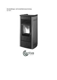
8.4. Quarterly cleaning<br />
ceramic glass<br />
ash compartment<br />
MANUAL<br />
PLATE POSITION<br />
8.4. Quarterly cleaning<br />
ceramic glass<br />
ash compartment<br />
PLATE POSITION<br />
UNSCREW THE PLATE<br />
-25-<br />
UNSCREW THE PLATE<br />
-25-<br />
display<br />
display<br />
Lift the glass panels<br />
VACUUM INSIDE<br />
Lift the glass panels<br />
VACUUM INSIDE<br />
clenaning stopper<br />
<strong>ILARIA</strong><br />
clenaning stopper<br />
MANUAL<br />
MANUAL<br />
<strong>ILARIA</strong><br />
In any case, check the firepot daily, as not all pellets have the same high quality standard.<br />
The glass is automatically cleaned by a flow of air; nonetheless, a slight grey film will tend to form<br />
on the glass after a few hours of operation. As mentioned previously, the <strong>ILARIA</strong> pellet <strong>stove</strong> must<br />
be fed with pellets with a diameter of 6 mm, however it can also be made to operate with pellets of<br />
different diameters; contact your ecoteck reseller for further details.<br />
3.1. Liability<br />
By providing this manual, ecoteck declines all liability, both civil and penal, for any accidents deriving<br />
from the failure to observe the instructions contained herein, in part or in full.<br />
Ecoteck declines all liability due to the improper use of the <strong>stove</strong>, incorrect operation by the user,<br />
unauthorised modifications and/or repairs, and the use of non-original spare parts for this model.<br />
The manufacturer declines all direct or indirect civil or penal liability due to:<br />
-poor maintenance<br />
-failure to observe the instructions contained in the manual<br />
-operation not compliant with the safety directives<br />
-installation not compliant with the national standards in force<br />
-installation by unqualified and untrained personnel<br />
-modifications and repairs not authorised by the manufacturer<br />
-use of non-original spare parts<br />
-extraordinary events<br />
3.2. Spare parts<br />
Only use original spare parts.<br />
Never wait for the components to be completely worn out before replacing them.<br />
Replace a worn component before it is completely broken, so as to prevent any accidents due to the<br />
sudden breakage of the components that may cause serious damage to people or things.<br />
Perform the periodical maintenance checks, as described in chapter 8.2.<br />
3.3. What are pellets wood?<br />
Wood pellets are made from sawdust and shavings of wood products produced in sawmills. The<br />
material used must not contain any other substances, for example glue, lacquer or synthetic substances.<br />
Subjected to high pressure, the wood is pressed through a die with holes; due to the high<br />
pressure, the sawdust heats up and the natural gums in the wood are activated. In this way, the<br />
pellets hold their shape even without the addition of adhesives. The density of wood pellets varies<br />
according to type of wood used, and may exceed 1.5 - 2 times the density of natural wood.<br />
-6-<br />
<strong>ILARIA</strong><br />
In any case, check the firepot daily, as not all pellets have the same high quality standard.<br />
The glass is automatically cleaned by a flow of air; nonetheless, a slight grey film will tend to form<br />
on the glass after a few hours of operation. As mentioned previously, the <strong>ILARIA</strong> pellet <strong>stove</strong> must<br />
be fed with pellets with a diameter of 6 mm, however it can also be made to operate with pellets of<br />
different diameters; contact your ecoteck reseller for further details.<br />
3.1. Liability<br />
By providing this manual, ecoteck declines all liability, both civil and penal, for any accidents deriving<br />
from the failure to observe the instructions contained herein, in part or in full.<br />
Ecoteck declines all liability due to the improper use of the <strong>stove</strong>, incorrect operation by the user,<br />
unauthorised modifications and/or repairs, and the use of non-original spare parts for this model.<br />
The manufacturer declines all direct or indirect civil or penal liability due to:<br />
-poor maintenance<br />
-failure to observe the instructions contained in the manual<br />
-operation not compliant with the safety directives<br />
-installation not compliant with the national standards in force<br />
-installation by unqualified and untrained personnel<br />
-modifications and repairs not authorised by the manufacturer<br />
-use of non-original spare parts<br />
-extraordinary events<br />
3.2. Spare parts<br />
Only use original spare parts.<br />
Never wait for the components to be completely worn out before replacing them.<br />
Replace a worn component before it is completely broken, so as to prevent any accidents due to the<br />
sudden breakage of the components that may cause serious damage to people or things.<br />
Perform the periodical maintenance checks, as described in chapter 8.2.<br />
3.3. What are pellets wood?<br />
Wood pellets are made from sawdust and shavings of wood products produced in sawmills. The<br />
material used must not contain any other substances, for example glue, lacquer or synthetic substances.<br />
Subjected to high pressure, the wood is pressed through a die with holes; due to the high<br />
pressure, the sawdust heats up and the natural gums in the wood are activated. In this way, the<br />
pellets hold their shape even without the addition of adhesives. The density of wood pellets varies<br />
according to type of wood used, and may exceed 1.5 - 2 times the density of natural wood.<br />
-6-
MANUAL<br />
<strong>ILARIA</strong><br />
The cylindrical pellets have a diameter of 5 - 7 mm, a length that varies between 10 and 50 mm,<br />
and a weight of around 650 kg/m 3 . The low moisture content (8 - 10%) means they have a higher<br />
calorific value.<br />
The DIN 51731 standards define the quality of the pellets:<br />
Length : approx. 10 - 30 mm<br />
Diameter: approx. 6 - 10 mm.<br />
Density: approx. 650 kg/m 3<br />
Calorific value: approx. 4.9 kWh/kg<br />
Residual moisture: approx. 6 - 12 %<br />
Ash: 1.0 kg/dm 3<br />
The pellets must be transported and stored completely dry. Upon contact with moisture they swell<br />
up and can no longer be used. Consequently, they need to be protected against humidity and<br />
moisture both during transport and storage.<br />
4. Safety devices<br />
The <strong>ILARIA</strong> pellet <strong>stove</strong> features sophisticated safety systems that, if one of the parts breaks or<br />
there are faults in the flue, prevent damage to the <strong>stove</strong> and the home.<br />
In any case, when a problem occurs, the pellet feed system is immediately stopped.<br />
-7-<br />
THE PELLETS<br />
MANUAL <strong>ILARIA</strong> MANUAL<br />
<strong>ILARIA</strong><br />
The cylindrical pellets have a diameter of 5 - 7 mm, a length that varies between 10 and 50 mm,<br />
and a weight of around 650 kg/m 3 . The low moisture content (8 - 10%) means they have a higher<br />
calorific value.<br />
The DIN 51731 standards define the quality of the pellets:<br />
Length : approx. 10 - 30 mm<br />
Diameter: approx. 6 - 10 mm.<br />
Density: approx. 650 kg/m 3<br />
Calorific value: approx. 4.9 kWh/kg<br />
Residual moisture: approx. 6 - 12 %<br />
Ash: 1.0 kg/dm 3<br />
The pellets must be transported and stored completely dry. Upon contact with moisture they swell<br />
up and can no longer be used. Consequently, they need to be protected against humidity and<br />
moisture both during transport and storage.<br />
4. Safety devices<br />
THE PELLETS<br />
The <strong>ILARIA</strong> pellet <strong>stove</strong> features sophisticated safety systems that, if one of the parts breaks or<br />
there are faults in the flue, prevent damage to the <strong>stove</strong> and the home.<br />
In any case, when a problem occurs, the pellet feed system is immediately stopped.<br />
MANUAL<br />
To clean the glass, use a damp rag with at most<br />
a few sprays of window cleaner.<br />
When cleaning the glass, always check<br />
that the grey gasket around the glass is in<br />
good condition; a worn gasket will affect the<br />
operation of the <strong>stove</strong>.<br />
To remove the flame trap, pull it out of the<br />
supports.<br />
Vacuum up all the ash that has deposited on the<br />
flame trap and reposition it correctly, with the bent<br />
side facing upwards, as shown in the figure.<br />
After a few hours of operation, it is normal for<br />
the flame trap to show deposits on surface.<br />
-7- -24-<br />
-24-<br />
<strong>ILARIA</strong>
MANUAL <strong>ILARIA</strong><br />
Only a clean and unblocked firepot will ensure trouble-free operation of the pellet <strong>stove</strong>. During operation,<br />
deposits may form in the firepot, and these must be removed immediately.<br />
The need to clean the firepot can be seen visually, and must be checked daily, at the latest after filling<br />
the pellets in the hopper. For rapid cleaning, the firepot can be left in the <strong>stove</strong>, however if the residues<br />
are hard to remove, take the firepot out and scrape it clean.<br />
The cleaning interval depends on the quality of the pellets used.<br />
Important: even with a new batch of pellets, despite being the same brand, there may be differences in<br />
combustion, and consequently the firepot may require more or less cleaning.<br />
8.3. Periodical cleaning ( every 3 to 5 days )<br />
8.3.1. Ash in the combustion chamber<br />
To remove the ash from the combustion chamber, the <strong>stove</strong> must already have cooled down and<br />
the switch must be moved to position “0”. Remove the firepot, remove the flame trap, open the ash<br />
compartment and use a cylinder vacuum cleaner with a fine mesh filter, so that the ash vacuumed<br />
up is not blown back into the room.<br />
Open the door and remove the ash compartment.<br />
Remove all the ash deposited inside<br />
using a cylinder vacuum cleaner. This operation<br />
will need to be performed at varying intervals,<br />
depending on the quality of pellets used<br />
MANUAL<br />
-23-<br />
<strong>ILARIA</strong><br />
Only a clean and unblocked firepot will ensure trouble-free operation of the pellet <strong>stove</strong>. During operation,<br />
deposits may form in the firepot, and these must be removed immediately.<br />
The need to clean the firepot can be seen visually, and must be checked daily, at the latest after filling<br />
the pellets in the hopper. For rapid cleaning, the firepot can be left in the <strong>stove</strong>, however if the residues<br />
are hard to remove, take the firepot out and scrape it clean.<br />
The cleaning interval depends on the quality of the pellets used.<br />
Important: even with a new batch of pellets, despite being the same brand, there may be differences in<br />
combustion, and consequently the firepot may require more or less cleaning.<br />
8.3. Periodical cleaning ( every 3 to 5 days )<br />
8.3.1. Ash in the combustion chamber<br />
To remove the ash from the combustion chamber, the <strong>stove</strong> must already have cooled down and<br />
the switch must be moved to position “0”. Remove the firepot, remove the flame trap, open the ash<br />
compartment and use a cylinder vacuum cleaner with a fine mesh filter, so that the ash vacuumed<br />
up is not blown back into the room.<br />
Open the door and remove the ash compartment.<br />
Remove all the ash deposited inside<br />
using a cylinder vacuum cleaner. This operation<br />
will need to be performed at varying intervals,<br />
depending on the quality of pellets used<br />
-23-<br />
MANUAL<br />
In any case, when a problem occurs, the pellet feed system is immediately stopped.<br />
There are two main “mechanical” safety devices:<br />
VACUUM SWITCH<br />
It measures the correct negative pressure<br />
(draught) in the flue; if there are draught problems<br />
or blockages along the flue gas exhaust pipes, the<br />
switch is activated, stopping the feed screw.<br />
MANUAL<br />
-8-<br />
<strong>ILARIA</strong><br />
If one of these safety mechanisms is activated, the display will show the corresponding error<br />
code.<br />
4.1. No flame in the fireport<br />
During the ignition phase, the flame may not ignite in the firepot. In this case, the control unit<br />
automatically shuts down the <strong>stove</strong>. There are various reasons why this may occur.<br />
4.2. Temporary power failure<br />
THERMOSTAT WHIT MANUAL<br />
RESET<br />
If the hopper should overheat due to the<br />
malfunction of the tangential fan, the thermostat is<br />
activated, stopping the feed screw<br />
If the power failure lasts only a few seconds, the <strong>stove</strong> resumes normal operation. If, on the other<br />
hand, it lasts a number of minutes, once the sensors measure a temperature below the threshold,<br />
the control unit will start the shutdown phase, and the <strong>stove</strong> will switch off after around 15 minutes.<br />
When there is no power, some smoke may be released into the room; this is not a problem, as<br />
there is always only a small quantity of pellets in the firepot. After shutdown, the control unit will<br />
start the <strong>stove</strong> again.<br />
In any case, when a problem occurs, the pellet feed system is immediately stopped.<br />
There are two main “mechanical” safety devices:<br />
VACUUM SWITCH<br />
It measures the correct negative pressure<br />
(draught) in the flue; if there are draught problems<br />
or blockages along the flue gas exhaust pipes, the<br />
switch is activated, stopping the feed screw.<br />
<strong>ILARIA</strong><br />
If one of these safety mechanisms is activated, the display will show the corresponding error<br />
code.<br />
4.1. No flame in the fireport<br />
During the ignition phase, the flame may not ignite in the firepot. In this case, the control unit<br />
automatically shuts down the <strong>stove</strong>. There are various reasons why this may occur.<br />
4.2. Temporary power failure<br />
THERMOSTAT WHIT MANUAL<br />
RESET<br />
If the hopper should overheat due to the<br />
malfunction of the tangential fan, the thermostat is<br />
activated, stopping the feed screw<br />
If the power failure lasts only a few seconds, the <strong>stove</strong> resumes normal operation. If, on the other<br />
hand, it lasts a number of minutes, once the sensors measure a temperature below the threshold,<br />
the control unit will start the shutdown phase, and the <strong>stove</strong> will switch off after around 15 minutes.<br />
When there is no power, some smoke may be released into the room; this is not a problem, as<br />
there is always only a small quantity of pellets in the firepot. After shutdown, the control unit will<br />
start the <strong>stove</strong> again.<br />
-8-
MANUAL<br />
5. Assembly, installation and start-up<br />
5.1. Assembly<br />
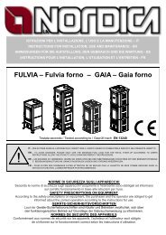
5.1.1. Dimensions<br />
45<br />
5.1.2. Positioning<br />
93<br />
45<br />
-9-<br />
33.5<br />
<strong>ILARIA</strong><br />
The position of the <strong>stove</strong> inside the home is fundamental to being able to uniformly heat the<br />
environment. Before deciding where to install the <strong>stove</strong>, remember that:<br />
- the combustion air must not be drawn in from a garage or a space without ventilation or fresh air,<br />
but rather from a free space or from the outside;<br />
- installation in bedrooms is not recommended;<br />
- installation is preferable in a large and central room of the home so as to ensure maximum<br />
circulation of the heat;<br />
- the <strong>stove</strong> should be plugged into an earthed power socket (if the cable supplied is not long<br />
enough to reach the power socket, use an extension cord running at floor level).<br />
MANUAL <strong>ILARIA</strong> MANUAL<br />
<strong>ILARIA</strong><br />
5. Assembly, installation and start-up<br />
5.1. Assembly<br />
5.1.1. Dimensions<br />
45<br />
5.1.2. Positioning<br />
93<br />
45<br />
33.5<br />
The position of the <strong>stove</strong> inside the home is fundamental to being able to uniformly heat the<br />
environment. Before deciding where to install the <strong>stove</strong>, remember that:<br />
- the combustion air must not be drawn in from a garage or a space without ventilation or fresh air,<br />
but rather from a free space or from the outside;<br />
- installation in bedrooms is not recommended;<br />
- installation is preferable in a large and central room of the home so as to ensure maximum<br />
circulation of the heat;<br />
- the <strong>stove</strong> should be plugged into an earthed power socket (if the cable supplied is not long<br />
enough to reach the power socket, use an extension cord running at floor level).<br />
19<br />
19<br />
MANUAL<br />
8. Cleaning and maintenance<br />
Before performing any maintenance operations on the <strong>stove</strong>, adopt the following precautions:<br />
8. Cleaning and maintenance<br />
Before performing any maintenance operations on the <strong>stove</strong>, adopt the following precautions:<br />
-9- -22-<br />
-22-<br />
<strong>ILARIA</strong><br />
- Check that all the parts of the <strong>stove</strong> are cold.<br />
- Make sure that the ash is completely extinguished.<br />
- Make sure that the main switch is in position zero.<br />
- Make sure that the <strong>stove</strong> is unplugged from the power socket, thus avoiding accidental contacts.<br />
- Always use suitable equipment, so as to avoid damaging the screws and require service by an<br />
authorised technical.<br />
- Following the maintenance phase, check that everything is the same condition as before starting<br />
the work.<br />
Important<br />
please heed the following cleaning instructions carefully! Failure to follow the<br />
instructions may cause operating problems of the <strong>stove</strong>.<br />
8.1. Cleaning the surfaces<br />
To clean the surfaces of the painted metal parts, use a rag dipped in water or soap and water. Note<br />
that the use of aggressive detergents or thinners will damage the surfaces of the <strong>stove</strong>.<br />
8.2. Daily cleaning<br />
Check that the firepot where combustion takes place is clean, and that any slag or residue does not<br />
block the holes, so as to always guarantee excellent combustion and avoid overheating that may<br />
cause the paint on the door to change colour or peel.<br />
Firepot properly cleaned with all the<br />
holes clearly visible<br />
Firepot that requires cleaning, with the<br />
holes blocked by the ash<br />
Firepot that requires cleaning, with the<br />
holes blocked by the ash
MANUAL <strong>ILARIA</strong><br />
7.5.3. Language<br />
The language can be selected from Italian, German, French and English.<br />
To access the setting, select the LINGUA [SET LANGUAGE] menu and use buttons P4 and P5 to<br />
select the desired language.<br />
7.5.4. Stove status<br />
The STATO STUFA [STOVE STATUS] menu displays the exhaust fan speed, the set room<br />
temperature and the status of the screw conveyor.<br />
7.5.5. Operating hours menu<br />
The ORE LAVORO [OPERATING HOURS] menu item shows the total operating hours of the<br />
<strong>stove</strong>.<br />
7.5.6. Display Settings menu<br />
Many of the operating parameters of the <strong>stove</strong> are loaded at power-up from an external flash<br />
memory to the microcontroller. To display these parameters and the corresponding values, enter the<br />
VEDI TARATURE [DISPLAY SETTINGS] menu and use P6 and P7 to scroll the list. The complete<br />
list is shown at the end of the chapter.<br />
7.5.7. Databank menu (password-protected)<br />
All the parameters can be set together based on a preset table (Database) resident in the ROM<br />
on the microcontroller. Enter the BANCA DATI [DATABANK] menu, use P5 to set the value “00” as<br />
the ACCESS KEY (or “o1”, “o2”,… if there is more than one databank) and confirm by pressing P6.<br />
The message “DATI CARICATI” [DATA LOADED] confirms the operation.<br />
MANUAL<br />
-21-<br />
-21-<br />
<strong>ILARIA</strong><br />
7.5.3. Language<br />
The language can be selected from Italian, German, French and English.<br />
To access the setting, select the LINGUA [SET LANGUAGE] menu and use buttons P4 and P5 to<br />
select the desired language.<br />
7.5.4. Stove status<br />
The STATO STUFA [STOVE STATUS] menu displays the exhaust fan speed, the set room<br />
temperature and the status of the screw conveyor.<br />
7.5.5. Operating hours menu<br />
The ORE LAVORO [OPERATING HOURS] menu item shows the total operating hours of the<br />
<strong>stove</strong>.<br />
7.5.6. Display Settings menu<br />
Many of the operating parameters of the <strong>stove</strong> are loaded at power-up from an external flash<br />
memory to the microcontroller. To display these parameters and the corresponding values, enter the<br />
VEDI TARATURE [DISPLAY SETTINGS] menu and use P6 and P7 to scroll the list. The complete<br />
list is shown at the end of the chapter.<br />
7.5.7. Databank menu (password-protected)<br />
All the parameters can be set together based on a preset table (Database) resident in the ROM<br />
on the microcontroller. Enter the BANCA DATI [DATABANK] menu, use P5 to set the value “00” as<br />
the ACCESS KEY (or “o1”, “o2”,… if there is more than one databank) and confirm by pressing P6.<br />
The message “DATI CARICATI” [DATA LOADED] confirms the operation.<br />
MANUAL<br />
5.1.3. Minimum distance between the <strong>stove</strong> and other materials<br />
MANUAL<br />
20cm<br />
If positioned in this way, leave at least 20 cm from the walls<br />
10cm<br />
-10-<br />
-10-<br />
10cm<br />
20cm<br />
If positioned in this way, leave at least 10 cm from the walls<br />
-side wall of the <strong>stove</strong> 20 cm<br />
-shelving above 20 cm<br />
-floor protection 20cm<br />
These indications may change due to regional or national standards. Always comply with the<br />
standards in force in the country where the <strong>stove</strong> is installed (contact your authorised ecoteck<br />
reseller).<br />
5.1.3. Minimum distance between the <strong>stove</strong> and other materials<br />
20cm<br />
If positioned in this way, leave at least 20 cm from the walls<br />
10cm<br />
10cm<br />
20cm<br />
If positioned in this way, leave at least 10 cm from the walls<br />
-side wall of the <strong>stove</strong> 20 cm<br />
-shelving above 20 cm<br />
-floor protection 20cm<br />
These indications may change due to regional or national standards. Always comply with the<br />
standards in force in the country where the <strong>stove</strong> is installed (contact your authorised ecoteck<br />
reseller).<br />
<strong>ILARIA</strong><br />
<strong>ILARIA</strong>
MANUAL<br />
5.2. Installation<br />
5.2.1. Stove gas exaust<br />
<strong>ILARIA</strong><br />
The gas exhaust system works due to the negative pressure in the combustion chamber and the<br />
slight positive pressure in the gas exhaust pipe. The gas exhaust system must therefore be airtight,<br />
using special pipes (steel, not aluminium) containing special silicone gaskets.<br />
The gas exhaust must run outside and must not terminate in closed or semi-closed spaces, such as<br />
garages, attics or any place where the gas may concentrate.<br />
The best solution for the gas exhaust recommended by ecoteck involves least 1.5 m of vertical steel<br />
pipe connected to the gas exhaust outlet on the rear of the <strong>stove</strong> via a T-joint, either inside or outside<br />
the room, and in any case then connected to the outside so as to create a natural current and<br />
prevent the possibility of smoke and odours being released inside when shutting down the <strong>stove</strong>.<br />
The surfaces of the outlet pipe may reach a high enough temperature as to cause burns when<br />
touched by children.<br />
For this reason use a non-combustible protective grate.<br />
5.2.2. Flue<br />
The operation of the pellet <strong>stove</strong> <strong>ILARIA</strong> is independent of the draught of the chimney, as the flue<br />
gas exhaust fan blows the gas from the combustion chamber into the chimney.<br />
If the draught in the chimney is very high, however, a regulating flap should be installed between the<br />
combustion chamber and the chimney<br />
5.2.2. Outside air intake<br />
In closed rooms with reduced air renewal, the operation of the pellet <strong>stove</strong> <strong>ILARIA</strong> may cause a<br />
reduction in the amount of oxygen present.<br />
With this outside air intake, the air required for combustion can be drawn in from the outside.<br />
5.3. Start-up<br />
MANUAL <strong>ILARIA</strong> MANUAL<br />
<strong>ILARIA</strong><br />
5.2. Installation<br />
5.2.1. Stove gas exaust<br />
The gas exhaust system works due to the negative pressure in the combustion chamber and the<br />
slight positive pressure in the gas exhaust pipe. The gas exhaust system must therefore be airtight,<br />
using special pipes (steel, not aluminium) containing special silicone gaskets.<br />
The gas exhaust must run outside and must not terminate in closed or semi-closed spaces, such as<br />
garages, attics or any place where the gas may concentrate.<br />
The best solution for the gas exhaust recommended by ecoteck involves least 1.5 m of vertical steel<br />
pipe connected to the gas exhaust outlet on the rear of the <strong>stove</strong> via a T-joint, either inside or outside<br />
the room, and in any case then connected to the outside so as to create a natural current and<br />
prevent the possibility of smoke and odours being released inside when shutting down the <strong>stove</strong>.<br />
The surfaces of the outlet pipe may reach a high enough temperature as to cause burns when<br />
touched by children.<br />
For this reason use a non-combustible protective grate.<br />
5.2.2. Flue<br />
The operation of the pellet <strong>stove</strong> <strong>ILARIA</strong> is independent of the draught of the chimney, as the flue<br />
gas exhaust fan blows the gas from the combustion chamber into the chimney.<br />
If the draught in the chimney is very high, however, a regulating flap should be installed between the<br />
combustion chamber and the chimney<br />
5.2.2. Outside air intake<br />
In closed rooms with reduced air renewal, the operation of the pellet <strong>stove</strong> <strong>ILARIA</strong> may cause a<br />
reduction in the amount of oxygen present.<br />
With this outside air intake, the air required for combustion can be drawn in from the outside.<br />
5.3. Start-up<br />
The <strong>ILARIA</strong> pellet <strong>stove</strong> should be installed by the distributor<br />
of an authorised installed<br />
5.3.1. Starting for the first time<br />
1- Before starting the <strong>stove</strong> carefully read the user and maintenance manual.<br />
2- Remove all the equipment placed inside the hopper when packing the <strong>stove</strong>.<br />
The <strong>ILARIA</strong> pellet <strong>stove</strong> should be installed by the distributor<br />
of an authorised installed<br />
5.3.1. Starting for the first time<br />
-11-<br />
1- Before starting the <strong>stove</strong> carefully read the user and maintenance manual.<br />
2- Remove all the equipment placed inside the hopper when packing the <strong>stove</strong>.<br />
-11-<br />
MANUAL<br />
-20-<br />
<strong>ILARIA</strong><br />
7.5.2. Timer thermostat<br />
The timer thermostat function allows the <strong>stove</strong> on/off times to be set for each day of the week,<br />
with two independent programs (PROGRAM 1 and PROGRAM 2). Select the SET CRONO [SET<br />
TIMER] menu item. Use buttons P6 and P7 to scroll the parameters, and P4 and P5 to change the<br />
values. The parameters can be set at any time, however they only become active when parameter<br />
UT01 in the SET OROLOGIO [SET CLOCK] menu is set to any value other than OFF (usually the<br />
current day).<br />
Parameter Description Possible values<br />
UT05 START PROGRAM 1 From 00:00 to 23:50 in steps of 10’<br />
UT06 STOP PROGRAM 1 From 00:00 to 23:50 in steps of 10’<br />
UT07 ON DAYS 1 On or off for days 1 to 7<br />
Pr36 PROGRAM 1 HEAT From 1 to 5<br />
UT09 START PROGRAM 2 From 00:00 to 23:50 in steps of 10’<br />
UT10 STOP PROGRAM 2 From 00:00 to 23:50 in steps of 10’<br />
UT11 ON DAYS 2 On or off for days 1 to 7<br />
Pr40 PROGRAM 2 HEAT From 1 to 5<br />
UT05-UT6 These two parameters indicate the start and stop times for PROGRAM 1.<br />
UT07 When the PROGRAM 1 setting is enabled, button P5 is used to select the day of<br />
the week, and button P4 enables/disables the operation of the <strong>stove</strong>.<br />
Pr36 This parameter indicates the heat output when PROGRAM 1 is running.<br />
UT09–UT10 These two parameters indicate the start and stop times for PROGRAM 2<br />
UT011 When the PROGRAM 2 setting is enabled, button P5 is used to select the day of<br />
the week, and button P4 enables/disables the operation of the <strong>stove</strong>.<br />
Pr40 This parameter indicates the heat output when PROGRAM 2 is running. In the<br />
following example, the <strong>stove</strong> is started on Saturday and Sunday from 08:00 to 13:00 at<br />
heat level 2, and everyday from 17:00 to 22:00 at heat level 3.<br />
PROGRAM 1 PROGRAM 2<br />
UT1=0800,UT2=1300,Pr36=2 UT09=1700,UT10=2200,Pr40=3<br />
Ut07 ON DAYS 1 Ut11 ON DAYS 2<br />
1 Off 1 On<br />
2 Off 2 On<br />
3 Off 3 On<br />
4 Off 4 On<br />
5 Off 5 On<br />
6 On 6 On<br />
7 On 7 On<br />
-20-<br />
7.5.2. Timer thermostat<br />
The timer thermostat function allows the <strong>stove</strong> on/off times to be set for each day of the week,<br />
with two independent programs (PROGRAM 1 and PROGRAM 2). Select the SET CRONO [SET<br />
TIMER] menu item. Use buttons P6 and P7 to scroll the parameters, and P4 and P5 to change the<br />
values. The parameters can be set at any time, however they only become active when parameter<br />
UT01 in the SET OROLOGIO [SET CLOCK] menu is set to any value other than OFF (usually the<br />
current day).<br />
Parameter Description Possible values<br />
UT05 START PROGRAM 1 From 00:00 to 23:50 in steps of 10’<br />
UT06 STOP PROGRAM 1 From 00:00 to 23:50 in steps of 10’<br />
UT07 ON DAYS 1 On or off for days 1 to 7<br />
Pr36 PROGRAM 1 HEAT From 1 to 5<br />
UT09 START PROGRAM 2 From 00:00 to 23:50 in steps of 10’<br />
UT10 STOP PROGRAM 2 From 00:00 to 23:50 in steps of 10’<br />
UT11 ON DAYS 2 On or off for days 1 to 7<br />
Pr40 PROGRAM 2 HEAT From 1 to 5<br />
UT05-UT6 These two parameters indicate the start and stop times for PROGRAM 1.<br />
UT07 When the PROGRAM 1 setting is enabled, button P5 is used to select the day of<br />
the week, and button P4 enables/disables the operation of the <strong>stove</strong>.<br />
Pr36 This parameter indicates the heat output when PROGRAM 1 is running.<br />
UT09–UT10 These two parameters indicate the start and stop times for PROGRAM 2<br />
UT011 When the PROGRAM 2 setting is enabled, button P5 is used to select the day of<br />
the week, and button P4 enables/disables the operation of the <strong>stove</strong>.<br />
Pr40 This parameter indicates the heat output when PROGRAM 2 is running. In the<br />
following example, the <strong>stove</strong> is started on Saturday and Sunday from 08:00 to 13:00 at<br />
heat level 2, and everyday from 17:00 to 22:00 at heat level 3.<br />
PROGRAM 1 PROGRAM 2<br />
UT1=0800,UT2=1300,Pr36=2 UT09=1700,UT10=2200,Pr40=3<br />
Ut07 ON DAYS 1 Ut11 ON DAYS 2<br />
1 Off 1 On<br />
2 Off 2 On<br />
3 Off 3 On<br />
4 Off 4 On<br />
5 Off 5 On<br />
6 On 6 On<br />
7 On 7 On
MANUAL <strong>ILARIA</strong><br />
7.5. Menu functions<br />
To access the menus, hold P4 for 2 seconds, scroll the list using P4/P5 until reaching the desired<br />
item and confirm by pressing P6. The following items are available:<br />
• SET OROLOGIO [SET CLOCK] menu<br />
• SET CRONO [SET TIMER] menu<br />
• LINGUA [LANGUAGE] menu<br />
• STATO STUFA [STOVE STATUS] menu<br />
• ORE LAVORO [OPERATING HOURS] menu<br />
• VEDI TARATURE [DISPLAY SETTINGS] menu<br />
• BANCA DATI [DATABASE MENU] (password-protected)<br />
• AZZERA ORE [RESET HOURS] menu (password-protected)<br />
• TARATURE FABBRICA [FACTORY SETTINGS] menu (password-protected)<br />
Some menus provide access to user functions, while others are for technicians only and require<br />
the password to be entered.<br />
7.5.1. Clock<br />
To use this function, the power board must be fitted with the optional module. Select the SET<br />
OROLOGIO [SET CLOCK] menu item. Use buttons P6 and P7 to scroll the parameters, and P4<br />
and P5 to change the values. The clock has the following parameters:<br />
Parameter Description Possible values<br />
UT01 CLOCK DAY OFF; Day1, ...;Day7<br />
UT02 CLOCK HOUR from 0 to 23<br />
UT03 CLOCK MINUTES from 00 to 60<br />
UT01 This parameter is used to set the current day or disable the programming of the timer<br />
thermostat.<br />
Day 1 Monday<br />
Day 2 Tuesday<br />
Day 3 Wednesday<br />
Day 4 Thursday<br />
Day 5 Friday<br />
Day 6 Saturday<br />
Day 7 Sunday<br />
Off Disabled<br />
UT02 This parameter is used to set the current hour<br />
UT03 This parameter is used to set the current minutes<br />
MANUAL<br />
7.5. Menu functions<br />
-19-<br />
<strong>ILARIA</strong><br />
To access the menus, hold P4 for 2 seconds, scroll the list using P4/P5 until reaching the desired<br />
item and confirm by pressing P6. The following items are available:<br />
• SET OROLOGIO [SET CLOCK] menu<br />
• SET CRONO [SET TIMER] menu<br />
• LINGUA [LANGUAGE] menu<br />
• STATO STUFA [STOVE STATUS] menu<br />
• ORE LAVORO [OPERATING HOURS] menu<br />
• VEDI TARATURE [DISPLAY SETTINGS] menu<br />
• BANCA DATI [DATABASE MENU] (password-protected)<br />
• AZZERA ORE [RESET HOURS] menu (password-protected)<br />
• TARATURE FABBRICA [FACTORY SETTINGS] menu (password-protected)<br />
Some menus provide access to user functions, while others are for technicians only and require<br />
the password to be entered.<br />
7.5.1. Clock<br />
To use this function, the power board must be fitted with the optional module. Select the SET<br />
OROLOGIO [SET CLOCK] menu item. Use buttons P6 and P7 to scroll the parameters, and P4<br />
and P5 to change the values. The clock has the following parameters:<br />
Parametro Descrizione Valori impastabili<br />
UT01 CLOCK DAY OFF; Day1, ...;Day7<br />
UT02 CLOCK HOUR from 0 to 23<br />
UT03 CLOCK MINUTES from 00 to 60<br />
UT01 This parameter is used to set the current day or disable the programming of the timer<br />
thermostat.<br />
Day 1 Monday<br />
Day 2 Tuesday<br />
Day 3 Wednesday<br />
Day 4 Thursday<br />
Day 5 Friday<br />
Day 6 Saturday<br />
Day 7 Sunday<br />
Off Disabled<br />
UT02 This parameter is used to set the current hour<br />
UT03 This parameter is used to set the current minutes<br />
-19-<br />
MANUAL<br />
MANUAL<br />
<strong>ILARIA</strong><br />
3- Unwind the room probe on the rear of the <strong>stove</strong>, making sure it doesn’t rest on hot surfaces.<br />
4- Correctly connect the pellet <strong>stove</strong> to the flue.<br />
5- Fill the hopper with pellets (diameter 6 mm).<br />
6- Open the door and check that the firepot is properly in position and that the flame trap is in place,<br />
towards the top of the combustion chamber.<br />
7- Close the door. Never open the door when the pellet <strong>stove</strong> is on.<br />
8- Connect the <strong>stove</strong> to a power socket using the special cable supplied.<br />
9- Move the switch located behind the <strong>stove</strong> to position “1”.<br />
10- Load the pellets, as described in the corresponding chapter.<br />
11- Press the start button for 2 seconds; the control unit will start the ignition cycle.<br />
5.3.2. Possible problems when starting for the first time<br />
No flame forms: When starting for the first time, too few pellets may fall into the firepot, thus<br />
preventing the flame from lighting.<br />
Solution: Open the door and empty the firepot. Replace the firepot in position and press the start<br />
button again. The ignition phase will recommence from the beginning.<br />
IMPORTANT:<br />
When starting for the first time make sure the room is well ventilated, as in the first few hours of<br />
operation unpleasant odours may be produced due to the fumes from the paint and the grease in<br />
the tube bundle.<br />
6. Tips<br />
Do not switch the <strong>stove</strong> on intermittently. This may cause sparks that shorten the life of the electrical<br />
components.<br />
Do not touch the <strong>stove</strong> with wet hands. The <strong>stove</strong> contains electrical components, and may<br />
cause discharges if not handled correctly. Only authorised technicians can resolve any operating<br />
problems.<br />
Do not remove any screws from the combustion chamber if they have not first been properly<br />
lubricated.<br />
Check that the firepot is correctly positioned.<br />
For any other problems contact your ecoteck installer<br />
<strong>ILARIA</strong><br />
3- Unwind the room probe on the rear of the <strong>stove</strong>, making sure it doesn’t rest on hot surfaces.<br />
4- Correctly connect the pellet <strong>stove</strong> to the flue.<br />
5- Fill the hopper with pellets (diameter 6 mm).<br />
6- Open the door and check that the firepot is properly in position and that the flame trap is in place,<br />
towards the top of the combustion chamber.<br />
7- Close the door. Never open the door when the pellet <strong>stove</strong> is on.<br />
8- Connect the <strong>stove</strong> to a power socket using the special cable supplied.<br />
9- Move the switch located behind the <strong>stove</strong> to position “1”.<br />
10- Load the pellets, as described in the corresponding chapter.<br />
11- Press the start button for 2 seconds; the control unit will start the ignition cycle.<br />
5.3.2. Possible problems when starting for the first time<br />
No flame forms: When starting for the first time, too few pellets may fall into the firepot, thus<br />
preventing the flame from lighting.<br />
Solution: Open the door and empty the firepot. Replace the firepot in position and press the start<br />
button again. The ignition phase will recommence from the beginning.<br />
IMPORTANT:<br />
When starting for the first time make sure the room is well ventilated, as in the first few hours of<br />
operation unpleasant odours may be produced due to the fumes from the paint and the grease in<br />
the tube bundle.<br />
6. Tips<br />
-12-<br />
Do not switch the <strong>stove</strong> on intermittently. This may cause sparks that shorten the life of the electrical<br />
components.<br />
Do not touch the <strong>stove</strong> with wet hands. The <strong>stove</strong> contains electrical components, and may<br />
cause discharges if not handled correctly. Only authorised technicians can resolve any operating<br />
problems.<br />
Do not remove any screws from the combustion chamber if they have not first been properly<br />
lubricated.<br />
Check that the firepot is correctly positioned.<br />
For any other problems contact your ecoteck installer<br />
-12-
MANUAL<br />
7. Operation<br />
7.1. Electronic board<br />
7.1.1. Wiring diagram<br />
Display connector<br />
Clock connector<br />
Serial<br />
connector<br />
<strong>ILARIA</strong><br />
MANUAL <strong>ILARIA</strong> MANUAL<br />
<strong>ILARIA</strong><br />
7. Operation<br />
7.1. Electronic board<br />
7.1.1. Wiring diagram<br />
Display connector<br />
Clock connector<br />
Serial<br />
connector<br />
Cn3<br />
Cn8<br />
Optional<br />
inputs<br />
Cn3<br />
Cn8<br />
Optional<br />
inputs<br />
Trasformator<br />
Trasformator<br />
Microprocessor<br />
Microprocessor<br />
Cn9<br />
Cn9<br />
Ignition relay<br />
Ignition relay<br />
N AL1 AL2 ACC COC<br />
N.PELLET N.H2O N.AMB TERM TC<br />
-13-<br />
Room probe<br />
External<br />
Thermostat<br />
Col. blue<br />
N AL1 AL2 ACC COC<br />
N.PELLET N.H2O N.AMB TERM TC<br />
Room probe<br />
External<br />
Thermostat<br />
Col. blue<br />
EXCH. GAS N L<br />
Flue Gas<br />
thermocouple<br />
EXCH. GAS N L<br />
Flue Gas<br />
thermocouple<br />
Col. red<br />
Col. red<br />
Cn6<br />
Cn6<br />
Cn4<br />
Cn4<br />
Cn7<br />
Cn7<br />
Cn1<br />
Cn1<br />
Heart<br />
Line<br />
Neutral 230 Vac<br />
Heart<br />
Transformer 5x20 “F“ 4A fuse<br />
Screw<br />
Transformer 5x20 “F“ 4A fuse<br />
Line<br />
Neutral 230 Vac<br />
Screw<br />
Exhaust fan<br />
room fan<br />
ALF ALD<br />
Ignition<br />
heater<br />
Exhaust fan<br />
room fan<br />
ALF ALD<br />
Ignition<br />
heater<br />
M<br />
ALF=General safety thermostat<br />
ALD=Draught safety thermostat<br />
Model C023<br />
M<br />
ALF=General safety thermostat<br />
ALD=Draught safety thermostat<br />
Model C023<br />
MANUAL<br />
Pressing button P3 for a few seconds cancels the message from the display.<br />
HOT FUMI [HOT FLUE GAS]<br />
The alarm is signalled if the flue gas probe reads a temperature above 280°C.<br />
<strong>ILARIA</strong><br />
SONDA FUMI [FLUE GAS PROBE]<br />
The alarm is signalled if the flue gas temperature probe is broken or disconnected. The <strong>stove</strong> starts<br />
the shutdown procedure; after around 10 minutes it will switch off completely.<br />
VENTOLA GUASTA [FAN FAULT]<br />
The alarm is signalled if the controller does not detect the movement of the flue gas exhaust fan.<br />
This may mean that either the fan or enco der is broken.<br />
HOT PELLET [HOT PELLETS]<br />
The alarm is signalled if the thermostat with manual reset in the hopper is activated.<br />
PELLET ESAURITI [PELLETS FINISHED]<br />
The alarm is signalled if there are no more pellets in the hopper.<br />
MANCATA ACCENS- [FAILED IGNITION]<br />
The alarm is signalled if the <strong>stove</strong> does not reach 50°C in the 16 minutes available (the temperature<br />
ramp required is 3°C/minute).<br />
TERMICO A RIARMO [THERMAL W. RESET]<br />
The alarm is signalled if the thermal contact (with manual reset) opens. The <strong>stove</strong> starts the<br />
shutdown procedure; after around 10 minutes it will switch off completely.<br />
MANCA DERESS-[NO DRAUGHT]<br />
The alarm is signalled if the draught safety thermostat contact opens. The <strong>stove</strong> starts the shutdown<br />
procedure; after around 10 minutes it will switch off completely.<br />
BLACKOUT [BLACKOUT]<br />
The alarm is signalled if there is no mains power supply during the operating phase. When power<br />
returns, the display will show “BLACKOUT”. The flue gas exhaust fan is operated at maximum<br />
speed and the screw is off. When the flue gas temperature falls below the start-up threshold, the<br />
<strong>stove</strong> begins the ignition procedure again.<br />
-13- -18-<br />
Pressing button P3 for a few seconds cancels the message from the display.<br />
HOT FUMI [HOT FLUE GAS]<br />
The alarm is signalled if the flue gas probe reads a temperature above 280°C.<br />
SONDA FUMI [FLUE GAS PROBE]<br />
The alarm is signalled if the flue gas temperature probe is broken or disconnected. The <strong>stove</strong> starts<br />
the shutdown procedure; after around 10 minutes it will switch off completely.<br />
VENTOLA GUASTA [FAN FAULT]<br />
The alarm is signalled if the controller does not detect the movement of the flue gas exhaust fan.<br />
This may mean that either the fan or enco der is broken.<br />
HOT PELLET [HOT PELLETS]<br />
The alarm is signalled if the thermostat with manual reset in the hopper is activated.<br />
PELLET ESAURITI [PELLETS FINISHED]<br />
The alarm is signalled if there are no more pellets in the hopper.<br />
MANCATA ACCENS- [FAILED IGNITION]<br />
The alarm is signalled if the <strong>stove</strong> does not reach 50°C in the 16 minutes available (the temperature<br />
ramp required is 3°C/minute).<br />
TERMICO A RIARMO [THERMAL W. RESET]<br />
The alarm is signalled if the thermal contact (with manual reset) opens. The <strong>stove</strong> starts the<br />
shutdown procedure; after around 10 minutes it will switch off completely.<br />
MANCA DERESS-[NO DRAUGHT]<br />
The alarm is signalled if the draught safety thermostat contact opens. The <strong>stove</strong> starts the shutdown<br />
procedure; after around 10 minutes it will switch off completely.<br />
BLACKOUT [BLACKOUT]<br />
The alarm is signalled if there is no mains power supply during the operating phase. When power<br />
returns, the display will show “BLACKOUT”. The flue gas exhaust fan is operated at maximum<br />
speed and the screw is off. When the flue gas temperature falls below the start-up threshold, the<br />
<strong>stove</strong> begins the ignition procedure again.<br />
-18-
MANUAL <strong>ILARIA</strong><br />
7.3.4. Economy phase (or flue gas modulation)<br />
The flue gas modulation phase occurs if the flue gas temperature reaches the maximum threshold<br />
of 250°C (parameter Pr14) or the room temperature reaches the “SET TEMPERATURE”. During<br />
this phase, the flue gas exhaust fan and the exchanger are operated at maximum speed, while<br />
the screw conveyor operates at minimum speed; the display will show the message “ECONOMIA”<br />
[ECONOMY]. The procedure has the purpose of lowering the flue gas temperature; when this<br />
returns below the threshold, the speeds of the three motors are restored according to the previous<br />
setting. To avoid possible shutdowns due to the strong draught and the low pellet feed during this<br />
phase, when the temperature falls below 90°C (parameter Pr12), the <strong>stove</strong> goes into ON1 mode<br />
(still displaying “ECONOMIA”) until reaching 105°C.<br />
7.3.5. Shtdown<br />
The <strong>stove</strong> is shut down by pressing P3 (ON/OFF) for a few seconds. The feed screw motor is<br />
stopped, the flue gas exhaust fan operates at the preset speed (parameter Pr58) and the display<br />
shows the message “PULIZIA FINALE” [FINAL CLEANING]. When the temperature of the flue gas<br />
falls to the minimum operating threshold (parameter Pr13), the exchanger is switched off, followed<br />
by the exhaust fan, after 10 minutes.<br />
7.4. Alarm managment<br />
If an operating fault occurs, the control system stops the <strong>stove</strong> and informs the user of the fault via<br />
an alarm message.<br />
Display Alarm<br />
HOT FUMI [HOT FLUE GAS] Flue gas temperature<br />
SONDA FUMI [FLUE GAS PROBE] Flue gas temperature probe<br />
VENTOLA GUASTA [FAN FAULT] Exhaust fan<br />
HOT PELLET [HOT PELLETS] <strong>Pellet</strong> temperature<br />
PELLET ESAURITI [PELLETS FINISHED] <strong>Pellet</strong> finished<br />
MANCATA ACCENS- [FAILED IGNITION] No ignition<br />
TERMICO A RIARMO [THERMAL W.RESET] General safety thermostat<br />
MANCA DEPRESS- [NO DRAUGHT] Draught safety thermostat<br />
BLACKOUT [BLACKOUT] No mains power<br />
MANUAL<br />
-17-<br />
<strong>ILARIA</strong><br />
7.3.4. Economy phase (or flue gas modulation)<br />
The flue gas modulation phase occurs if the flue gas temperature reaches the maximum threshold<br />
of 250°C (parameter Pr14) or the room temperature reaches the “SET TEMPERATURE”. During<br />
this phase, the flue gas exhaust fan and the exchanger are operated at maximum speed, while<br />
the screw conveyor operates at minimum speed; the display will show the message “ECONOMIA”<br />
[ECONOMY]. The procedure has the purpose of lowering the flue gas temperature; when this<br />
returns below the threshold, the speeds of the three motors are restored according to the previous<br />
setting. To avoid possible shutdowns due to the strong draught and the low pellet feed during this<br />
phase, when the temperature falls below 90°C (parameter Pr12), the <strong>stove</strong> goes into ON1 mode<br />
(still displaying “ECONOMIA”) until reaching 105°C.<br />
7.3.5. Shtdown<br />
The <strong>stove</strong> is shut down by pressing P3 (ON/OFF) for a few seconds. The feed screw motor is<br />
stopped, the flue gas exhaust fan operates at the preset speed (parameter Pr58) and the display<br />
shows the message “PULIZIA FINALE” [FINAL CLEANING]. When the temperature of the flue gas<br />
falls to the minimum operating threshold (parameter Pr13), the exchanger is switched off, followed<br />
by the exhaust fan, after 10 minutes.<br />
7.4. Alarm managment<br />
If an operating fault occurs, the control system stops the <strong>stove</strong> and informs the user of the fault via<br />
an alarm message.<br />
Display Alarm<br />
HOT FUMI [HOT FLUE GAS] Flue gas temperature<br />
SONDA FUMI [FLUE GAS PROBE] Flue gas temperature probe<br />
VENTOLA GUASTA [FAN FAULT] Exhaust fan<br />
HOT PELLET [HOT PELLETS] <strong>Pellet</strong> temperature<br />
PELLET ESAURITI [PELLETS FINISHED] <strong>Pellet</strong> finished<br />
MANCATA ACCENS- [FAILED IGNITION] No ignition<br />
TERMICO A RIARMO [THERMAL W.RESET] General safety thermostat<br />
MANCA DEPRESS- [NO DRAUGHT] Draught safety thermostat<br />
BLACKOUT [BLACKOUT] No mains power<br />
-17-<br />
MANUAL<br />
7.1.2. Description of the controls and the symbols on the display<br />
MANUAL<br />
-14-<br />
-14-<br />
<strong>ILARIA</strong><br />
P1 – Decrease heat: • When in set heat mode or in operating mode, and the room temperature is<br />
less than the temperature set point, this button is used to decrease the heat output set by the user,<br />
from the maximum value of 5 to the minimum value of 1; the value is shown on the display.<br />
P2 – Increase heat: • When in set heat mode or in operating mode, and the room temperature is less<br />
than the temperature set point, this button is used to increase the heat output set by the user, from<br />
the minimum value of 1 to the maximum value of 5; the value is shown on the display • During the<br />
ignition phase, if pressed for 3 seconds, the <strong>stove</strong> passes directly to the operating phase.<br />
P3 – ON/OFF: • ressed for two seconds, manually starts or stops the <strong>stove</strong>, depending on whether<br />
it is already off or on. • If alarms have occurred which forced the <strong>stove</strong> to shut down, this button<br />
resets the alarms and switches the operating status to off.<br />
P4 – Decrease temperature / Menu: • When in set room temperature mode, this button is used to<br />
set the desired value, from a maximum of 41°C to a minimum of 6°C. • Pressing for 3 seconds this<br />
button allows the access to the list of user/technician parameters and scrolls the list. • When setting<br />
the user/technician parameters, it decreases the value of the selected parameter.<br />
P5 – Increase temperature: • When in set room temperature mode, this button is used to set the<br />
desired value, from a minimum of 6°C to a maximum of 41°C. • Scrolls the list of menus. • When<br />
setting the user/technician parameters, it decreases the value of the selected parameter.<br />
P6 – Decrease pellet-air mixture / Select menu: • Pressed together with P7 it accesses the<br />
parameter for calibrating the pellet-air mixture and decreases the value, from a maximum of 100 to<br />
a minimum of 00. • Inside the list of menus, it selects a menu and scrolls the corresponding list of<br />
parameters.<br />
P7 – Incremento della miscela pellet-aria: • Pressed together with P6 it accesses the parameter<br />
for calibrating the pellet-air mixture and increases the value, from a minimum of 00 to a maximum<br />
of 100. • Inside a menu, it scrolls the list of parameters. If pressed inside the main list of menus, it<br />
directly accesses the STOVE STATUS menu.<br />
7.1.2. Description of the controls and the symbols on the display<br />
<strong>ILARIA</strong><br />
P1 – Decrease heat: • When in set heat mode or in operating mode, and the room temperature is<br />
less than the temperature set point, this button is used to decrease the heat output set by the user,<br />
from the maximum value of 5 to the minimum value of 1; the value is shown on the display.<br />
P2 – Increase heat: • When in set heat mode or in operating mode, and the room temperature is less<br />
than the temperature set point, this button is used to increase the heat output set by the user, from<br />
the minimum value of 1 to the maximum value of 5; the value is shown on the display • During the<br />
ignition phase, if pressed for 3 seconds, the <strong>stove</strong> passes directly to the operating phase.<br />
P3 – ON/OFF: • ressed for two seconds, manually starts or stops the <strong>stove</strong>, depending on whether<br />
it is already off or on. • If alarms have occurred which forced the <strong>stove</strong> to shut down, this button<br />
resets the alarms and switches the operating status to off.<br />
P4 – Decrease temperature / Menu: • When in set room temperature mode, this button is used to<br />
set the desired value, from a maximum of 41°C to a minimum of 6°C. • Pressing for 3 seconds this<br />
button allows the access to the list of user/technician parameters and scrolls the list. • When setting<br />
the user/technician parameters, it decreases the value of the selected parameter.<br />
P5 – Increase temperature: • When in set room temperature mode, this button is used to set the<br />
desired value, from a minimum of 6°C to a maximum of 41°C. • Scrolls the list of menus. • When<br />
setting the user/technician parameters, it decreases the value of the selected parameter.<br />
P6 – Decrease pellet-air mixture / Select menu: • Pressed together with P7 it accesses the<br />
parameter for calibrating the pellet-air mixture and decreases the value, from a maximum of 100 to<br />
a minimum of 00. • Inside the list of menus, it selects a menu and scrolls the corresponding list of<br />
parameters.<br />
P7 – Incremento della miscela pellet-aria: • Pressed together with P6 it accesses the parameter<br />
for calibrating the pellet-air mixture and increases the value, from a minimum of 00 to a maximum<br />
of 100. • Inside a menu, it scrolls the list of parameters. If pressed inside the main list of menus, it<br />
directly accesses the STOVE STATUS menu.
MANUAL<br />
Display<br />
The LCD shows all the messages required for the operation of the <strong>stove</strong>.<br />
IR Receiver<br />
IR receiver for remote control (optional).<br />
7.2. User functions<br />
<strong>ILARIA</strong><br />
7.2.1. Setting the heat output<br />
The heat output is set using buttons P1 and P2 on a value between 1 (minimum) and 5<br />
(maximum). The selected value is shown on the display. The setting can be made at any time,<br />
both before the ignition of the <strong>stove</strong> and when the <strong>stove</strong> is in operation, but not in the economy<br />
phase (see the paragraph on Economy phase).<br />
7.2.2. Setting the temperature<br />
The temperature setting can be made using buttons P4 and P5, between a minimum value of 7<br />
and a maximum value of 40. The selected value is shown on the display. The setting can be made<br />
at any time, both before the ignition of the <strong>stove</strong> and when the <strong>stove</strong> is in operation.<br />
7.2.3. Settaggio della miscela pellet-aria.<br />
Setting the air - pellet blend allows the speed of both the smoke engine and the pellet feeding<br />
screw to be changed simultaneously. This allows combustion to be adjusted according to the<br />
<strong>stove</strong>’s draught and according to the hardness of the pellet. To access adjustment press P6 and<br />
P7 together until “0 PELLET 0 DRAUGHT” appears.<br />
The quantity of pellet is changed with keys 4 and 5.<br />
The speed of the smoke engine is changed with keys 6 and 7.<br />
This screen will appear on the display<br />
Valori <strong>Pellet</strong><br />
From 0 to -5 i decrease the pellet load<br />
0 Default value that considers the set combustion as excellent<br />
From 0 to 5 i increase the falling pellet<br />
Valori Tiraggio<br />
From 0 to -5 To be carried out when there is too much draught and when there is no flame in the <strong>stove</strong><br />
0 Default value that considers the set combustion as excellent<br />
From 0 to 5 To be carried out when the pellet to be used is too hard and a stronger draught is required<br />
in the combustion chamber<br />
N.B. They are two independent headings!<br />
7.3. Staring the <strong>stove</strong><br />
The <strong>stove</strong> is started and stopped manually by pressing button P3 (ON/OFF) for a few seconds. A<br />
complete operating cycle usually involves five separate phases (ignition, flame stabilisation, normal<br />
operation, economy and shutdown) which alternate according to the flue gas temperature measured<br />
and other operating parameters. These phases are explained in detail below.<br />
MANUAL <strong>ILARIA</strong> MANUAL<br />
<strong>ILARIA</strong><br />
Display<br />
The LCD shows all the messages required for the operation of the <strong>stove</strong>.<br />
IR Receiver<br />
IR receiver for remote control (optional).<br />
7.2. User functions<br />
0<br />
PELLET<br />
0<br />
DRAUGHT<br />
MANUAL<br />
<strong>ILARIA</strong><br />
7.3.1. Ignition phase<br />
The <strong>stove</strong> is started by pressing the ON/OFF button for a few seconds. The procedure starts<br />
by activating the ignition heater and continuously filling the pellets using the screw. The display<br />
shows, in sequence, the messages ACCENDE [IGNITION], CARICA PELLET [FEEDING PEL-<br />
LETS] and ATTESA FIAMMA [AWAITING FLAME]. After around 50 seconds (parameter Pr55), the<br />
gear motor stops and the exhaust fan is started (at the speed set by parameter Pr16). Once the<br />
pellets have been ignited and the flue gas temperature reaches 50°C (parameter Pr13), the heater<br />
switches off and the flame stabilisation phase starts. The ignition phase ends when the temperature<br />
reaches 50°C, however for safety reasons and to protect the heater, this phase can last a<br />
maximum of 16 minutes (parameter Pr02). If the pellets are not ignited, that is, the <strong>stove</strong> does<br />
not reach 50°C in the 16 minutes available, the display will show the “MANCATA ACCENSIONE”<br />
[FAILED IGNITION] alarm.<br />
7.3.2. Flame stabilisation phase<br />
In this phase, the screw conveyor feeds the pellets at the preset speed (parameter Pr05). When<br />
the flue gas temperature exceeds 110°C (parameter Pr11) with a ramp of 3°C/minute, the <strong>stove</strong> is<br />
ignited. In this flame stabilisation phase, the flue gas exhaust fan reaches the preset speed (parameter<br />
Pr17) and the temperature is measured to make sure it remains stable for a certain time<br />
(parameter Pr02); after this, the operating phase starts. The initial start-up phases can be skipped<br />
by holding button P2 (increase heat) for around 3 seconds; this automatically skips to the normal<br />
operation phase.<br />
7.3.3. Operating phase<br />
The board has an input for an external thermostat. The operating mode of the <strong>stove</strong> changes according<br />
to the external thermostat setting, the room thermostat setting and the room temperature<br />
measured.<br />
T Amb :room temperature measured by the probe<br />
T SetAmb :room temperature set for the SET TEMP AMBIENTE [ROOM SET TEMP]<br />
T SetTerm<br />
: room temperature set on the external thermostat<br />
• :External thermostat closed (T Amb > T SetTerm ): The display shows the message “ton” and the<br />
<strong>stove</strong> works at the set heat output until the thermostat opens.<br />
• :External thermostat open (T Amb < T SetTerm ): The <strong>stove</strong> works at the set heat output until<br />
reaching T SetAmb (T Amb < T SetAmb ), after which the economy phase starts (T Amb > T SetAmb ).<br />
-15- -16-<br />
7.2.1. Setting the heat output<br />
The heat output is set using buttons P1 and P2 on a value between 1 (minimum) and 5<br />
(maximum). The selected value is shown on the display. The setting can be made at any time,<br />
both before the ignition of the <strong>stove</strong> and when the <strong>stove</strong> is in operation, but not in the economy<br />
phase (see the paragraph on Economy phase).<br />
7.2.2. Setting the temperature<br />
The temperature setting can be made using buttons P4 and P5, between a minimum value of 7<br />
and a maximum value of 40. The selected value is shown on the display. The setting can be made<br />
at any time, both before the ignition of the <strong>stove</strong> and when the <strong>stove</strong> is in operation.<br />
7.2.3. Settaggio della miscela pellet-aria.<br />
Setting the air - pellet blend allows the speed of both the smoke engine and the pellet feeding<br />
screw to be changed simultaneously. This allows combustion to be adjusted according to the<br />
<strong>stove</strong>’s draught and according to the hardness of the pellet. To access adjustment press P6 and<br />
P7 together until “0 PELLET 0 DRAUGHT” appears.<br />
The quantity of pellet is changed with keys 4 and 5.<br />
The speed of the smoke engine is changed with keys 6 and 7.<br />
This screen will appear on the display<br />
Valori <strong>Pellet</strong><br />
From 0 to -5 i decrease the pellet load<br />
0 Default value that considers the set combustion as excellent<br />
From 0 to 5 i increase the falling pellet<br />
Valori Tiraggio<br />
From 0 to -5 To be carried out when there is too much draught and when there is no flame in the <strong>stove</strong><br />
0 Default value that considers the set combustion as excellent<br />
From 0 to 5 To be carried out when the pellet to be used is too hard and a stronger draught is required<br />
in the combustion chamber<br />
N.B. They are two independent headings!<br />
7.3. Staring the <strong>stove</strong><br />
0<br />
PELLET<br />
0<br />
DRAUGHT<br />
The <strong>stove</strong> is started and stopped manually by pressing button P3 (ON/OFF) for a few seconds. A<br />
complete operating cycle usually involves five separate phases (ignition, flame stabilisation, normal<br />
operation, economy and shutdown) which alternate according to the flue gas temperature measured<br />
and other operating parameters. These phases are explained in detail below.<br />
7.3.1. Ignition phase<br />
The <strong>stove</strong> is started by pressing the ON/OFF button for a few seconds. The procedure starts<br />
by activating the ignition heater and continuously filling the pellets using the screw. The display<br />
shows, in sequence, the messages ACCENDE [IGNITION], CARICA PELLET [FEEDING PEL-<br />
LETS] and ATTESA FIAMMA [AWAITING FLAME]. After around 50 seconds (parameter Pr55), the<br />
gear motor stops and the exhaust fan is started (at the speed set by parameter Pr16). Once the<br />
pellets have been ignited and the flue gas temperature reaches 50°C (parameter Pr13), the heater<br />
switches off and the flame stabilisation phase starts. The ignition phase ends when the temperature<br />
reaches 50°C, however for safety reasons and to protect the heater, this phase can last a<br />
maximum of 16 minutes (parameter Pr02). If the pellets are not ignited, that is, the <strong>stove</strong> does<br />
not reach 50°C in the 16 minutes available, the display will show the “MANCATA ACCENSIONE”<br />
[FAILED IGNITION] alarm.<br />
7.3.2. Flame stabilisation phase<br />
In this phase, the screw conveyor feeds the pellets at the preset speed (parameter Pr05). When<br />
the flue gas temperature exceeds 110°C (parameter Pr11) with a ramp of 3°C/minute, the <strong>stove</strong> is<br />
ignited. In this flame stabilisation phase, the flue gas exhaust fan reaches the preset speed (parameter<br />
Pr17) and the temperature is measured to make sure it remains stable for a certain time<br />
(parameter Pr02); after this, the operating phase starts. The initial start-up phases can be skipped<br />
by holding button P2 (increase heat) for around 3 seconds; this automatically skips to the normal<br />
operation phase.<br />
7.3.3. Operating phase<br />
The board has an input for an external thermostat. The operating mode of the <strong>stove</strong> changes according<br />
to the external thermostat setting, the room thermostat setting and the room temperature<br />
measured.<br />
T Amb :room temperature measured by the probe<br />
T SetAmb :room temperature set for the SET TEMP AMBIENTE [ROOM SET TEMP]<br />
T SetTerm<br />
: room temperature set on the external thermostat<br />
• :External thermostat closed (T Amb > T SetTerm ): The display shows the message “ton” and the<br />
<strong>stove</strong> works at the set heat output until the thermostat opens.<br />
• :External thermostat open (T Amb < T SetTerm ): The <strong>stove</strong> works at the set heat output until<br />
reaching T SetAmb (T Amb < T SetAmb ), after which the economy phase starts (T Amb > T SetAmb ).<br />
-15- -16-