Extraflame Ecologica Idro Manual - Narvells
Extraflame Ecologica Idro Manual - Narvells
Extraflame Ecologica Idro Manual - Narvells

You also want an ePaper? Increase the reach of your titles
YUMPU automatically turns print PDFs into web optimized ePapers that Google loves.
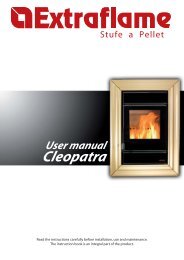
PELLET STOVES<br />
Instruction <strong>Manual</strong><br />
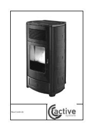
<strong>Ecologica</strong> <strong>Idro</strong><br />
Read these instructions carefully before installation, use and maintenance.<br />
The instruction booklet is an integral part of the product.
Congratulations! You are now the owner of an EXTRAFLAME stove!<br />
The EXTRAFLAME pellet stove is an ideal heating solution. It utilises the most advanced<br />
technology and is manufactured to the highest standards with a contemporary design,<br />
allowing you to enjoy the ambience and warmth of a natural flame in complete safety.<br />
This manual tells you how to use your stove correctly. Please read the entire manual<br />
carefully before using your stove.<br />
IMPORTANT<br />
Make sure that the dealer completes the following box with the details of the authorised<br />
specialist who will help you if you have any problems in using your new pellet stove.<br />
AUTHORISED SPECIALIST<br />
COMPANY________________________________________________________________<br />
NAME _______________________________________________________________<br />
ADDRESS _____________________________________________________________<br />
POST CODE ____________ CITY ____________________________________________<br />
TEL. ________________________ FAX _______________________________________<br />
All <strong>Extraflame</strong> products are manufactured according to the following directives:<br />
• 89/106 EEC (CPD) construction materials<br />
• 73/23 EEC (LVD) electrical safety<br />
• 98/37 EEC machinery<br />
• 2004/108 EEC (EMC) electromagnetic compatibility<br />
And the following standards:<br />
• EN14785<br />
• EN60335.1 EN50165 EN50366<br />
• EN292 EN294<br />
• EN55014.1 EN55014.2 EN61000-3-2 EN61000-3-3<br />
Page 2
Contents<br />
1 WARNINGS AND SAFETY 4<br />
2 TECHNICAL SPECIFICATIONS 5<br />
3 WHAT ARE PELLETS? 7<br />
3.1 Pellet storage 7<br />
3.2 Pellet loading 7<br />
4 SAFETY DEVICES 8<br />
4.1 Breakdown of hot air distribution fan 8<br />
4.2 Breakdown of flue gas extractor 8<br />
4.3 Breakdown of pellet load motor 8<br />
4.4 Failed ignition 8<br />
4.5 Temporary power cut 8<br />
4.6 Electrical safety device 8<br />
4.7 Flue gas exhaust safety device 8<br />
4.8 Pellet temperature safety device 8<br />
4.9 System pressure safety device 8<br />
4.10 Boiling water safety device 8<br />
4.11 External devices 8<br />
4.12 Installation and safety devices 9<br />
4.13 Safety devices for open tank systems 9<br />
4.14 Safety devices for closed tank systems 9<br />
5 ASSEMBLY AND INSTALLATION INSTRUCTIONS 10<br />
5.1 Glossary 10<br />
5.2 Installation 11<br />
5.2.1 Connection to the flue gas evacuation system 12<br />
5.2.2 Chimney or flue 13<br />
5.2.3 Connecting the appliance to the flue and evacuation of combustion products 15<br />
5.2.4 Chimney 15<br />
5.2.5 Connection to external air inlets 16<br />
5.2.6 Insulation, trims, facings and safety recommendations 16<br />
5.2.7 National, regional, provincial and municipal regulations 16<br />
6 CONTROL PANEL 17<br />
7 ADJUSTING CURRENT TIME 18<br />
8 USE 18<br />
9 IGNITION 18<br />
10 STOVE OPERATION 19<br />
10.1 Normal operation 19<br />
10.2 Switching-off 19<br />
10.3 Remote control 20<br />
11 ROOM THERMOSTAT 21<br />
11.1 Digital thermostat (standard) 21<br />
11.2 Mechanical thermostat (optional) 21<br />
11.2.1 Installation of mechanical thermostat (optional) 21<br />
11.2.2 Mechanical thermostat operation 21<br />
11.2.3 Mechanical thermostat operation in Stby mode (to be used with remote actuator) 21<br />
12 USER PARAMETERS 23<br />
12.1 Water temperature adjustment 23<br />
12.2 Weekly programmer 23<br />
12.3 Day/night temperature function 26<br />
12.4 Pellet load adjustment 28<br />
13 CLEANING 29<br />
13.1 Connection to the chimney 30<br />
14 WIRING DIAGRAM 31<br />
15 STOVE DISPLAY MESSAGE TABLES 33<br />
16 WARRANTY 36<br />
17 QUALITY CONTROL 38<br />
18 COMPATIBILITY WITH RoHS AND WEEE DIRECTIVES 39<br />
Page 3
1. WARNINGS AND SAFETY<br />
The stoves produced in our factory are built with<br />
maximum dedication to the individual components<br />
so as to protect both the user and the installer<br />
from accidents. Authorised personnel are therefore<br />
advised to pay special attention to the electrical<br />
connections, above all after any servicing<br />
operation on the product, especially with regard to<br />
the stripped part of the wires, which must not<br />
protrude in any way from the terminal block to<br />
prevent possible contact with the live parts of the<br />
wire.<br />
Installation must be carried out by<br />
authorised personnel, who have to provide a<br />
declaration of conformity of the appliance<br />
for the purchaser, who will then be fully<br />
responsible for the permanent installation<br />
and consequent correct operation of the<br />
installed product. It is necessary to bear in<br />
mind all the national, regional, provincial<br />
and municipal laws and regulations present<br />
in the country in which the appliance is<br />
installed.<br />
<strong>Extraflame</strong> S.p.A. may not be held<br />
responsible in the event of failure to observe<br />
these precautions.<br />
This instruction manual constitutes an integral part<br />
of the product. It must always accompany the<br />
appliance, also when it is transferred to another<br />
owner or user or moved to another location. If the<br />
manual gets damaged or lost, ask your local<br />
service centre for another copy.<br />
This stove must only be used for the applications<br />
for which it was expressly designed.<br />
The manufacturer declines any responsibility,<br />
contractually or extra-contractually, for any<br />
damage caused to persons, animals or property by<br />
errors in installation, adjustment, and<br />
maintenance, or by improper use.<br />
After removing the packaging, check to make sure<br />
that the contents are intact and complete.<br />
If this is not the case, contact the vendor from<br />
whom the appliance was purchased.<br />
The electrical components of the stove, to<br />
guarantee correct operation, must only be<br />
replaced with original spare parts from an<br />
authorised service centre.<br />
Page 4<br />
General stove maintenance must be carried out at<br />
least once a year, scheduled sufficiently in advance<br />
with the service centre.<br />
The following safety precautions must be<br />
observed:<br />
Do not allow the stove to be used by children or<br />
unassisted disabled persons.<br />
Do not touch the stove if you are bare-footed or if<br />
parts of your body are wet or damp.<br />
Modifying the safety or adjustment devices without<br />
the manufacturer’s approval or instructions is<br />
forbidden.<br />
Never pull, detach, or twist the electrical cables<br />
coming out of the stove, even if it is disconnected<br />
from the electrical power supply.<br />
Avoid blocking up or reducing the size of the air<br />
vents of the room in which the stove is installed.<br />
The air vents are critical for correct combustion.<br />
Keep the packaging materials out of the reach of<br />
children and unassisted disabled persons.<br />
During product operation the door of the furnace<br />
must always be closed.<br />
Avoid direct contact with parts of the appliance<br />
which tend to heat up during functioning.<br />
Check for the presence of any obstructions before<br />
switching the appliance on following a long<br />
standstill period.<br />
The stove has been designed to function in any<br />
climatic conditions (even critical), in particularly<br />
adverse conditions (strong wind, ice) safety<br />
systems may intervene, which switch the stove off.<br />
If this happens, contact the after-sales service and<br />
under no circumstances disable the safety systems.<br />
If the flue should catch fire use suitable systems to<br />
suffocate the flames or request help from the fire<br />
brigade.
2. TECHNICAL SPECIFICATIONS<br />
Features Unit<br />
Valore<br />
Value<br />
Weight kg 159<br />
Height mm 955<br />
Width mm 667<br />
Depth mm 671<br />
Flue gas exhaust pipe diameter mm 80<br />
Air extraction pipe diameter mm 50<br />
Max. overall thermal power kW 16<br />
Max. useful thermal power kW 12.5<br />
- output air power kW 1.0<br />
- output water power kW 11.5<br />
Min. useful thermal power kW 3.5<br />
- output air power kW 0.5<br />
- output water power kW 3.0<br />
Min. hourly fuel consumption kg/h 0.8<br />
Max. hourly fuel consumption kg/h 3.2<br />
Tank capacity kg ~ 30<br />
Recommended chimney draught Pa ~ 10<br />
Chimney draught at max useful power Pa 12<br />
Chimney draught at min useful power Pa 10<br />
Rated electrical power W 310<br />
Rated voltage Vac 230<br />
Rated frequency Hz 50<br />
Water inlet/outlet pipe diameter “ 3/4<br />
Automatic discharge pipe diameter “ -<br />
Pump head m 4<br />
Max accepted working water power bar 1.5<br />
CO measured at max useful power % 0.024<br />
CO measured at min useful power % 0.033<br />
Efficiency at max useful power % 80.8<br />
Efficiency at min useful power % 91.5<br />
Exhaust gas temp. at max useful power °C 214<br />
Exhaust gas temp. at min useful power °C 76.8<br />
Mass of gases emitted at max useful power g/s 15.17<br />
Mass of gases emitted at min useful power g/s 6.38<br />
Tests carried out using wooden pellets as fuel, with calorific value of 4.9 kW/h/kg.<br />
The data stated above is a reference and not binding. The manufacturer reserves the right to carry<br />
out any modifications in order to improve the performance of the product.<br />
Page 5
Page 6
3. WHAT ARE PELLETS?<br />
Pellets are made by applying very high pressure to sawdust; i.e. the residue of raw timber<br />
(without paint) produced by sawmills, carpentry works and other activities involved in processing<br />
wood.<br />
This type of fuel is completely environmentally friendly, as no binders of any kind are used to keep<br />
it compact. In fact, the compactness of the pellets over time is guaranteed by lignite, a natural<br />
substance found in the wood itself.<br />
As well as being an environmentally friendly fuel, since wood residues are exploited to the<br />
maximum, pellets also have technical advantages.<br />
While the heating power of wood is 4.4 kW/kg (with 15% humidity, after about 18 months<br />
seasoning), the power of pellets is 5.3 kW/kg.<br />
The density of the pellet is 650kg/m 3 and the water content is 8% of its weight. For this reason,<br />
pellets do not need to be seasoned to obtain a sufficient heating yield.<br />
The pellet used must conform to the characteristics of the following regulations:<br />
• Ö-Norm M 7135<br />
• DIN plus 51731<br />
• UNI CEN/TS 14961<br />
<strong>Extraflame</strong> recommends always using 6 mm pellets for its products.<br />
3.1 Pellet storage<br />
To guarantee problem-free combustion, the pellets must be stored in a dry place.<br />
3.2 Pellet loading<br />
To load the pellets, open the tank cover positioned on the upper part of the stove and empty the<br />
bag of pellets, paying attention not to let them escape.<br />
WARNING<br />
THE USE OF POOR QUALITY PELLETS OR ANY OTHER MATERIAL MAY DAMAGE YOUR STOVE<br />
AND MAY LEAD TO THE INVALIDATION OF THE WARRANTY AND THE RELATED<br />
RESPONSIBILITIES OF THE MANUFACTURER.<br />
Page 7
4. SAFETY DEVICES<br />
4.1 Breakdown of hot air distribution fan<br />
If the blower stops for any reason, the stove automatically shuts down to prevent overheating<br />
4.2 Breakdown of flue gas extractor<br />
If the extractor stops, the electronic unit immediately prevents pellet feeding.<br />
4.3 Breakdown of pellet load motor<br />
If the motor stops, the stove continues to operate until the minimum cooling level is reached.<br />
4.4 Failed ignition<br />
If no flame develops during the ignition phase, the appliance automatically attempts a new ignition, this<br />
time, though, without loading pellets.<br />
If, after this attempt, the stove still has no flame, the stove display shows “FAILED IGNITION”. If you<br />
attempt to light the stove again, the display shows “COOLING WAIT” which means “WAIT”.<br />
This function reminds you that before lighting the stove, you must be sure that the brazier is<br />
free of dirt and debris.<br />
4.5 Temporary power cut<br />
The appliance will re-light automatically after a brief power failure. When the power goes off, the stove may<br />
emit a minute quantity of smoke inside the house for a period of 3 to 5 minutes.<br />
THIS DOES NOT POSE ANY SAFETY RISK.<br />
4.6 Electrical safety device<br />
The stove is protected against violent changes in power by a master fuse on the rear of the stove (2A 250V<br />
delayed).<br />
4.7 Flue gas exhaust safety device<br />
If the exhaust system fails, an electronic pressure switch stops the stove and an alarm is signalled.<br />
4.8 Pellet temperature safety device<br />
In case of overheating inside the pellet tank, this safety device blocks stove operation; resetting is manual<br />
and must be performed by an authorised technician.<br />
4.9 System pressure safety device<br />
A mechanical pressure switch blocks any over-pressure in the system.<br />
Resetting is manual and must be carried out by an authorised technician.<br />
4.10 Boiling water safety device<br />
In the event of a lack or minimum quantity of water, this device blocks the pellet feed. Reset is manual and<br />
must be carried out by an authorised technician.<br />
4.11 External devices<br />
During stove installation, it is MANDATORY to adapt the system with a pressure gauge for viewing the water<br />
pressure and an automatic discharge valve calibrated at 3 bar pressure.<br />
Page 8
4.12 Installation and safety devices<br />
The installation and respective system connections, the start-up and final testing for correct operation must<br />
be carried out with all due diligence by authorised professional technicians (Italian Law no. 46 of 5 March<br />
1990), in full respect for the regulations in force, both national and regional, as well as for the instructions<br />
given in this manual.<br />
<strong>Extraflame</strong> S.p.A. declines any responsibility for damage to objects and/or persons caused by<br />
the system.<br />
4.13 Safety devices for open expansion tank system<br />
According to the UNI 10412-2 (2006) regulation, in force in Italy, systems with open expansion tank must be<br />
equipped with:<br />
• Open expansion tank<br />
• Safety tube<br />
• Loading tube<br />
• Thermostat for circulator control (excluded for systems with natural circulation)<br />
• Circulation system (excluded for systems with natural circulation)<br />
• Device for acoustic alarm activation<br />
• Acoustic alarm<br />
• Temperature indicator<br />
• Pressure indicator<br />
• Automatic cut-out switch (cut-out thermostat)<br />
The temperature safety sensors must be on-board the heat generator or at a distance no greater than 30 cm<br />
from the delivery connection.<br />
If the heat generators are not equipped with all the devices, the missing ones can be installed on the<br />
delivery piping of the generator, at a distance of no more than 1 m from it.<br />
4.14 Safety devices for closed tank system<br />
According to the UNI 10412-2 (2006) regulation, in force in Italy, closed systems must be equipped with:<br />
• Safety valve<br />
• Circulator control thermostat<br />
• Acoustic alarm activation thermostat<br />
• Temperature indicator<br />
• Pressure indicator<br />
• Acoustic alarm<br />
• Automatic thermal adjustment switch<br />
• Automatic thermal cut-out switch (cut-out thermostat)<br />
• Circulation system<br />
• Expansion system<br />
• Safety dissipation system incorporated into the generator with the blowdown valve (self-operated),<br />
if the appliance is not equipped with a self-regulating temperature system<br />
The temperature safety sensors must be on-board the heat generator or at a distance no greater than 30 cm<br />
from the delivery connection.<br />
If the generators are not equipped with all the devices, the missing ones can be installed on the delivery<br />
piping of the generator, at a distance of no more than 1 m from the machine.<br />
Domestic type automatic loading heating appliances must be equipped with a fuel blocking thermostat or a<br />
cooling circuit provided by the manufacturer of the appliance, activated by a thermal safety valve in order to<br />
guarantee that the temperature limit imposed by the regulation is not exceeded. The connection between<br />
the power supply unit and the valve must not have interceptions. The pressure upstream from the cooling<br />
circuit must be at least 1.5 bar.<br />
Page 9
5. ASSEMBLY AND INSTALLATION INSTRUCTIONS<br />
The installation must comply with:<br />
UNI 10683 (2005) heat generators fed with wood and other solid fuels: installation.<br />
The chimneys must comply with:<br />
UNI 9731 (1990) chimneys: classification according to thermal resistance.<br />
EN 13384-1 (2006) calculation method of the thermal and fluid-dynamic features of the chimney.<br />
UNI 7129 point 4.3.3 provisions, local rules and prescriptions of the fire brigade.<br />
UNI 1443 (2005) chimneys: general requirements.<br />
UNI 1457 (2004) chimneys: internal ducts in terracotta and ceramics.<br />
5.1 Glossary<br />
CLOSED HEARTH DEVICE<br />
Heat generator that can only be opened to load fuel during use.<br />
BIOMASS<br />
Material of organic origin, excluding the material incorporated in geological formations and<br />
fossilised.<br />
BIOFUEL<br />
Fuel produced directly or indirectly from biomass.<br />
FLUE or CHIMNEY<br />
Vertical pipe for collecting and expelling combustion products from a single appliance at a suitable<br />
height from the floor.<br />
EXHAUST PIPE or FITTING<br />
Pipe or connecting element between the heat generating device and the chimney for extracting<br />
the combustion products.<br />
INSULATION<br />
The series of measures taken and materials used to prevent heat transmission through a wall<br />
dividing rooms at different temperatures.<br />
CHIMNEY CAP<br />
Device located at the top of the chimney that facilitates dispersion of the combustion products in<br />
the atmosphere.<br />
CONDENSATE<br />
Liquid products that form when the temperature of the combustion gas is lower than or equal to<br />
the dew point of the water.<br />
HEAT GENERATOR<br />
Device that permits the production of thermal energy (heat) by the rapid transformation of the<br />
chemical energy of the fuel by means of combustion.<br />
AIR LOCK<br />
Mechanism for modifying the dynamic resistance of the combustion gases.<br />
Page 10
FLUE GAS VENTING SYSTEM<br />
A system for flue gas exhaust venting that is independent from the appliance, composed of a pipe<br />
or channel, chimney or single flue, and chimney cap.<br />
FORCED DRAUGHT<br />
Air circulation by means of a fan driven by an electric motor.<br />
NATURAL DRAUGHT<br />
Draught resulting in a chimney/flue due to the difference in the volume mass existing between the<br />
(hot) fumes and the surrounding atmospheric air, without any mechanical suction aid installed<br />
inside or on top of it.<br />
RADIANCE AREA<br />
Area immediately adjacent to the hearth in which the heat produced by combustion is diffused;<br />
this area must not contain any objects made of combustible material.<br />
REFLUX AREA<br />
Area in which the combustion products come out from the appliance towards the room in which it<br />
is installed.<br />
5.2 Installation<br />
Before carrying out installation, it is necessary to check the positioning of the chimneys, flues or<br />
exhaust terminal ducts of the appliance, bearing in mind the following:<br />
• Installation prohibitions<br />
• Legal clearances<br />
• Limitations set out by local administrative regulations or specific regulations of the<br />
authorities.<br />
• Common limitations deriving from building regulations, and easement or contract<br />
regulations.<br />
Admissible installations<br />
In the room in which the heat generator is to be installed, any existing or installed appliances must<br />
be airtight to the room and must not cause depression in the room with respect to the external<br />
environment.<br />
Appliances used for cooking foods and the related hoods without extractor can only be installed in<br />
rooms used as kitchens.<br />
Prohibited installations<br />
The room in which the heat generator is to be installed must not contain any of the following<br />
devices, either pre-existing or installed:<br />
- Hoods with or without extractor;<br />
- Ventilation ducts of the collective type.<br />
Should these devices be located in adjacent rooms communicating with the installation room, it is<br />
forbidden to use the heat generator simultaneously where there is the risk that one of the two<br />
rooms may be subject to depression with respect to the other.<br />
Page 11
5.2.1 Connection to the flue gas venting system<br />
Exhaust pipe or fitting<br />
For the assembly of the exhaust pipes it is imperative to use non-flammable materials that are<br />
resistant to combustion products and any condensates.<br />
It is forbidden to use flexible metal pipes and asbestos cement for connecting the stove to the<br />
flue, also for pre-existing exhaust channels.<br />
There must be continuity between the exhaust pipe and the flue so that the flue does not lean on<br />
the stove.<br />
The exhaust pipes must not pass through rooms in which the installation of combustion devices is<br />
forbidden.<br />
The assembly of the exhaust pipes must be carried out in such a way as to ensure that they are<br />
airtight for the operating conditions of the appliance, as well as to limit the formation of<br />
condensates and prevent them from being conveyed towards the appliance.<br />
The assembly of horizontal sections must be avoided where possible.<br />
Where roof or wall exhaust outlets have to be reached that are not coaxial in relation to the<br />
exhaust outlet from the appliance, the direction changes must be made using open elbows no<br />
greater than 45° (see figures below).<br />
Insulation<br />
45° 45°<br />
For heat generating devices equipped with an electric exhaust fan, i.e. all products made by<br />
<strong>Extraflame</strong>, it is necessary to observe the following instructions:<br />
• Horizontal sections must have a minimum slope of 3% upwards.<br />
• The length of the horizontal section must be as short as possible, and in any case no<br />
greater than 3 metres.<br />
• No more than four direction changes may be used, including the one resulting from the use<br />
of the “T”-element. (When four bends are used, use double wall piping with a 100 mm<br />
diameter.)<br />
In any case, exhaust pipes must be sealed in relation to combustion products and condensates, as<br />
well as insulated, if they pass outside the installation room.<br />
It is forbidden to use elements in counter-slope.<br />
The exhaust channel must allow soot recovery and cleaning using a swab.<br />
The exhaust channel must have a constant cross-section. Any changes in cross-section are allowed<br />
only at the flue connection. It is forbidden to run other air feed channels or piping for utilities<br />
inside the exhaust channels, even if they are oversized. No manual draught regulation devices can<br />
be mounted on forced draught appliances.<br />
Page 12<br />
Flue<br />
Inspection
5.2.2 Chimney or single flue<br />
The chimney or flue must meet the following requirements:<br />
- be sealed to combustion products, waterproof and properly insulated according to the usage<br />
conditions;<br />
- be made of materials suitable to resist normal mechanical stress, as well as heat and the action<br />
of combustion products and any condensates;<br />
- have a predominantly vertical layout with deviations from the axis no greater than 45°;<br />
- be situated at a proper distance from combustible or flammable materials by means of an air gap<br />
or suitable insulation material;<br />
A<br />
REFERENCES<br />
Minimum 80 cm²<br />
Flooring protection<br />
Flammable<br />
objects<br />
Page 13<br />
Non-flammable<br />
objects<br />
A 200 100<br />
B 1500 750<br />
C 200 100<br />
- preferably have a round internal section: square or rectangular sections must have rounded<br />
edges with radius no less than 20 mm;<br />
- have a constant, free and independent internal section;<br />
- have rectangular sections with a maximum ratio between sides of 1.5.<br />
The exhaust pipe should be equipped with a chamber for the collection of solid materials and any<br />
condensates located below the mouth of the exhaust pipe, so that it is easy to open and inspect<br />
from the airtight hatch.<br />
B<br />
20 cm<br />
C
Maximum 3 m<br />
cm<br />
3 – 5 %<br />
Inspection<br />
External<br />
insulated duct<br />
Inspection<br />
Page 14<br />
Maximum 3 m<br />
cm<br />
Flue<br />
Windproof<br />
chimney cap<br />
Inspection<br />
45° Inspection
5.2.3 Connecting the appliance to the flue and evacuation of combustion products<br />
The flue must receive exhaust from a single heat generator.<br />
Direct discharge towards enclosed areas, even when roofless, is forbidden.<br />
Direct discharge of combustion products must take place on the roof and the exhaust pipe must<br />
have the features set out in the section “Chimney or single flue”.<br />
5.2.4 Chimney cap<br />
The chimney cap must meet the following requirements:<br />
- have an internal section equivalent to that of the chimney;<br />
- have a useful outlet section no less than twice the internal section of the chimney;<br />
- be constructed in such a way as to prevent the penetration of rain, snow and foreign bodies into<br />
the chimney, as well as to assure the discharge of the combustion products also in the presence of<br />
winds coming from any direction and at any angle.<br />
- be positioned in such a way as to assure proper dispersion and dilution of the combustion<br />
products and, in any case, outside the reflux area in which the formation of counter-pressure is<br />
most likely to occur. This area has different sizes and shapes depending on the slope of the roof;<br />
therefore, it is necessary to use the minimum heights indicated in the figures below.<br />
The chimney cap must not have any mechanical suction devices.<br />
FLAT ROOF<br />
SLOPING ROOF<br />
H min<br />
< 5 m<br />
50 cm<br />
Distance > A<br />
Distance < A<br />
β<br />
Page 15<br />
> 5 m<br />
< 5 m<br />
50 cm beyond the ridge beam<br />
REFLUX AREA<br />
50 cm<br />
Reflux area height
Roof pitch<br />
CHIMNEYS, DISTANCES AND POSITIONING<br />
Distance between the<br />
crown and the chimney<br />
Page 16<br />
Minimum height of the chimney<br />
(measured from the outlet)<br />
β A (m) H (m)<br />
15° < 1.85 0.50 m beyond the crown<br />
> 1.85 1.00 m from the roof<br />
30° < 1.50 0.50 m beyond the crown<br />
> 1.50 1.30 m from the roof<br />
45° < 1.30 0.50 m beyond the crown<br />
> 1.30 2.00 m from the roof<br />
60° < 1.20 0.50 m beyond the crown<br />
> 1.20 2.60 m from the roof<br />
5.2.5 Connection to external air inlets<br />
To ensure correct operation, the appliance must have sufficient air available by means of external<br />
air inlets, which must meet the following requirements:<br />
a) They must have a total free section of at least 80 cm².<br />
b) They must be protected by a grate, metal mesh, or other suitable protection provided that it<br />
does not reduce the minimum section as per point a) and that it is positioned in such a way as to<br />
prevent the intakes from being obstructed.<br />
If the combustion air is collected directly from the outside by means of a pipe, it is necessary to fit<br />
a downward bend or a wind hood on the outside. In addition, no grating or similar device should<br />
be positioned. (<strong>Extraflame</strong> S.p.A. suggests creating an air intake directly communicating with the<br />
installation room, even if air is collected from outside by means of a pipe). Air inflow can also be<br />
obtained from a room adjacent to the installation room, provided that the flow can occur freely<br />
through permanent openings communicating with the outside.<br />
The adjacent room must not be subject to depression with respect to the outside as a result of the<br />
opposing draught caused by the presence of another utility device or suction device in this room.<br />
In the adjacent room, the permanent openings must meet the requirements described above.<br />
The adjacent room cannot be used as a garage, storage area for combustible material, or for<br />
activities involving fire hazards.<br />
5.2.6 Insulation, trims, facings, and safety precautions<br />
The facings, no matter what type of material they are made of, must constitute a self-bearing<br />
structure with reference to the heating assembly and not in contact with it.<br />
The beam and the trims in wood or combustible materials must be positioned outside of the<br />
radiant area of the hearth or be properly insulated.<br />
If the space above the heat generator has coverings made of combustible or heat-sensitive<br />
material, a protective membrane made of non-combustible insulating material must be placed<br />
between it and the generator.<br />
All elements made of combustible or flammable material, such as wooden furnishings, curtains,<br />
etc., which are directly exposed to the radiance of the hearth, must be placed at a safe distance.<br />
The installation of the appliance must guarantee easy access for cleaning the appliance itself, of<br />
the exhaust gas pipes and the flue.<br />
5.2.7 National, regional, provincial and municipal laws<br />
All the national, regional, provincial ad municipal laws of the country where the appliance has been<br />
installed must be taken into consideration
6. CONTROL PANEL<br />
REMOTE CONTROL SENSOR D1 D2<br />
1 ON/OFF BUTTON<br />
The stove can be turned on and off automatically by pressing button 1.<br />
2-3 AIR TEMPERATURE SETTING<br />
Buttons 2 and 3 are used to adjust the room temperature inside the house.<br />
4-5 OPERATING POWER<br />
Buttons 4 and 5 are used to adjust the heating power and warm air ventilation.<br />
D1 Display for showing the various messages<br />
D2 Display for showing the heat setting<br />
Page 17
7. CURRENT TIME AND DAY SETTINGS<br />
To adjust these parameters follow the procedure below:<br />
1. Disconnect and reconnect the power supply from the stove using the master switch or the<br />
power cable.<br />
2. The stove will firstly visualise the microprocessor version (Id_40 or later), “TIME”, “Li 3”<br />
and then “OFF”.<br />
3. When “TIME” appears, press button 5 to access the adjustment mode.<br />
4. Display D1 will show the current time, the hours flash while the minutes are fixed: use<br />
keys 2 and 3 to adjust the hours and then confirm using key 5.<br />
5. At this point the hours are fixed and the minutes will start to flash: using keys 2 and 3,<br />
adjust the minutes.<br />
To go back to hour selection press button 4 again or exit and confirm using key 1.<br />
8. USE<br />
BASIC INSTRUCTIONS<br />
The stove you have purchased uses pellets as fuel. This type of material is produced from natural<br />
waste from woodworking. By means of a special process, which does not require the use of any<br />
binders or additives, the shavings are compressed in industrial machines under high pressure and<br />
become solid wooden pellets. IT IS STRICTLY FORBIDDEN to burn any other material besides<br />
pellets in our stove.<br />
Failure to respect these instructions will void all warranties and may jeopardise the safety of the<br />
appliance.<br />
The first two or three times the stove is lit, the following recommendations should be observed:<br />
• No children should be present, as the vapours emitted can be harmful for health. Adults,<br />
too, should not stay in the vicinity for very long.<br />
• Do not touch the surfaces, as they could still be unstable.<br />
• Air the room thoroughly several times.<br />
• The hardening of the surfaces is completed after several heating processes.<br />
• This stove must not be used as a waste incinerator.<br />
9. IGNITION<br />
1. Before proceeding, check to make sure that:<br />
a. the tank is loaded with pellets<br />
b. the combustion chamber is clean<br />
c. the brazier is clean and free<br />
d. the fire door and the ash drawer are sealed<br />
e. the power cable is connected correctly<br />
f. the two-way switch on the back of the stove is in position 1<br />
2. Press button 1 for three seconds; display D1 will show the message “At 08”, with the<br />
numbers decreasing every second. During this stage, the stove carries out an automatic<br />
check on the efficiency of each single electrical component. When this cycle is completed,<br />
display D1 shows the message Ac 15 (the number of minutes for which the stove<br />
attempts the lighting stage, decreasing by 1 every minute that passes).<br />
Page 18
NOTE: The first time the stove is used, even if the tank is loaded with pellets, it is possible<br />
that the pellets are not distributed to the combustion chamber for the first 15 minutes<br />
because the worm screw for loading the pellets is empty. If the stove has not developed a<br />
flame after the fifteen minutes have elapsed, the display shows the message “NO ACC”.<br />
In this case, press button 1 for three seconds until D1 shows the message “OFF”. Then<br />
repeat steps 1 and 2.<br />
3. If steps 1 and 2 are carried out correctly, as soon as the flame develops the stove enters<br />
the start-up phase (“Au 07”).<br />
4. After the start-up phase, the stove goes into normal operation: display D1 shows the room<br />
temperature and D2 shows the heat setting.<br />
WARNING!<br />
1. NEVER USE FLAMMABLE LIQUIDS FOR LIGHTING.<br />
2. WHEN FILLING, DO NOT BRING THE SACK OF PELLETS INTO CONTACT WITH THE<br />
HOT STOVE.<br />
N.B.: In the event of continued lighting failures, contact an authorised technician.<br />
10. STOVE OPERATION<br />
10.1 Normal operation<br />
Once the stove is lit, you can adjust the heat setting using buttons 4 and 5. Pressing button 4<br />
decreases the heat setting and hourly pellet consumption; pressing 5 increases them. In addition<br />
to the feed rate, the room temperature can be set directly from the control panel using button 2<br />
and 3. To set the water temperature of the system, see the “Water temperature adjustment”<br />
chapter.<br />
The stove adjusts itself automatically in relation to the warm air ventilation.<br />
The contents of the tank should be monitored to prevent the flame going out due to a lack of fuel.<br />
ATTENTION!<br />
1. The cover of the pellet container must always be kept closed except when loading<br />
fuel.<br />
2. The sacks of pellets must be kept at least 1.5 metres away from the stove.<br />
3. The tank should always be kept at least half full.<br />
4. Before refilling, make sure that the appliance is switched off.<br />
10.2 Shutdown<br />
Press button 1 for three seconds.<br />
When the three seconds have elapsed, the stove automatically starts the shutdown stage, cutting<br />
off the pellet feed. Display D1 shows the message “OFF”, the current time, and the room<br />
temperature in alternation.<br />
Both the exhaust motor and warm air ventilation motor continue to run until the stove temperature<br />
has dropped sufficiently.<br />
Page 19
10.3 Remote control<br />
The heat setting, the room temperature, and automatic start/stop of the stove can be remote<br />
controlled.<br />
S = Light that indicates which keys have<br />
been pressed.<br />
Correspondence of display keys with<br />
remote control keys<br />
1 = p3+p5<br />
2 = p2<br />
3 = p3<br />
4 = p4<br />
5 = p5<br />
To light the stove, press buttons 3 and 5 at the same time and hold for three seconds (Fig. 21);<br />
the stove automatically enters the lighting stage. This is followed by the start-up phase, which<br />
allows the stove to develop and settle the flame.<br />
When the lighting stage is complete, the stove goes into normal operation. The heat setting can<br />
be adjusted using the buttons 4 and 5, and the room temperature setting can be adjusted using<br />
buttons 2 and 3.<br />
To switch off the stove, press buttons 3 and 5 at the same time and hold for three seconds.<br />
Display D1 will show the message “OFF”.<br />
The remote control operates with an MN21 12V battery (the kind used for gate opening remote<br />
controls).<br />
To replace the batteries, open the cover in the rear part as illustrated below.<br />
Open by pressing the part circled in the figure<br />
Page 20<br />
S<br />
P3<br />
P2<br />
P5<br />
P4
11. ROOM THERMOSTAT<br />
11.1 Digital thermostat (standard)<br />
The stove can control the room temperature by means of a digital thermostat whose function is to<br />
lower the heating power to the minimum when a pre-set temperature is reached.<br />
1. When the stove has been started and has entered normal operating mode, a number<br />
(e.g. 21°C ) appears on display D1 indicating the room temperature.<br />
2. The thermostat can be set using button 2 or 3. A message appears on the display<br />
which alternates the word “Set” with the temperature set each time one of the buttons<br />
is pressed. Pressing 2 decreases the value and pressing 3 increases it.<br />
3. Wait until the message “Set” disappears from the display.<br />
4. Use buttons 4 and 5 to adjust the heat setting as desired.<br />
When the appliance reaches the set temperature, it automatically goes to the minimum operating<br />
condition and LED 1 on display D1 goes off.<br />
If you wish to exclude the digital thermostat, use button 3 to set the temperature to the maximum<br />
until “HOT” appears on display D1.<br />
The same functions can be obtained by remote control.<br />
11.2 Mechanical thermostat (optional)<br />
N.B.: Installation must be carried out by an authorised technician.<br />
A thermostat can be placed in a room adjacent to the one in which the stove is installed. Just<br />
connect a mechanical thermostat (like those used for boilers) following the procedure described<br />
below. (We recommend positioning the optional thermostat at a height of 1.50 m above floor<br />
level.)<br />
11.2.1 Installing a mechanical thermostat (optional)<br />
N.B.: Installation must be carried out by an authorised technician.<br />
1. Switch off the appliance using the master switch on the back of the stove.<br />
2. Disconnect the plug from the socket.<br />
3. Referring to the electrical wiring diagram, connect the two thermostat wires to the<br />
respective terminals on the back side of the stove, one red and one black<br />
11.2.2 Mechanical thermostat operation<br />
1. Light the stove using button 1.<br />
2. Set the desired heating power using buttons 4 and 5.<br />
3. Bring the room temperature to minimum using button 2; the display will show “Lou”.<br />
4. Set the desired room temperature on the thermostat (e.g. 21C°); the display will show “t<br />
on”.<br />
5. When the stove reaches the desired temperature, it goes to the minimum operating<br />
condition (“Lou” appears on D1). If the temperature drops, the stove will pass to “t on”<br />
again, returning to the setting previously made.<br />
Page 21
11.2.3 Mechanical thermostat operation in Standby mode (to be used also for remote<br />
actuator)<br />
The Standby function is used to further reduce pellet consumption by switching off the stove when<br />
the desired temperature has been reached.<br />
As the temperature drops, the stove will automatically switch on again.<br />
1. Set the desired temperature using buttons 4 and 5.<br />
2. Using button 2, set the room temperature at the minimum position until display D1 shows<br />
“Lou” with “Set” flashing.<br />
3. While “Lou” and “Set” are flashing, press button 1 for three seconds; the display shows<br />
Stby, which means that the energy saving function is on.<br />
At this point the thermostat will control the stove as described below:<br />
• Thermostat with closed contact: the stove switches on and operates at the power set.<br />
Display D1 shows “t on”.<br />
• Thermostat with open contact: the stove switches off or stays off, and display D1 shows<br />
“Stby”.<br />
This function can also be suspended temporarily by pressing button 1 for three seconds.<br />
• If the stove is in “Stby” phase, the stove remains off. Display D1 shows “Stby”, “off” and<br />
the current time.<br />
• If the stove is in “t on” phase, the stove switches off. Display D1 shows “t on”, “off” and<br />
the current time.<br />
To return to using this function, press button 1 again.<br />
To exclude this function altogether, just raise the stove thermostat temperature using button 3.<br />
Page 22
12. USER PARAMETERS<br />
USER PARAMETERS<br />
WATER TEMPERATURE ADJUSTMENT<br />
Display D1 Display D2 Function<br />
70°C Water temperature adjustment<br />
WEEKLY PROGRAMMER<br />
Display D1 Display D2 Function<br />
off 0 Act./ Deact. Weekly programmer<br />
00:00 1 1st ignition time<br />
00:00 2 1st switch-off time<br />
off 1 3 Consents for 1 st ignition /switch-off for the various days<br />
00 4 Installer parameter<br />
00:00 5 2nd ignition time<br />
00:00 6 2nd switch-off time<br />
off 1 7 Consents for 2 nd ignition/switch off for various days<br />
00:00 8 3 rd ignition time<br />
00:00 9 3 rd switch-off time<br />
off 1 A Consents for 3 rd ignition /switch-off for the various days<br />
DAY-NIGHT TEMPERATURE FUNCTION<br />
Display D1 Display D2 Function<br />
06:00 B Start day period/ end night period<br />
22:00 C Start night period/ end day period<br />
25 D Day period max. temperature<br />
20 E Night period max. temperature<br />
PELLET LOAD ADJUSTMENT<br />
Display D1 Display D2 Function<br />
00 F % pellet load adjustment<br />
12.1 Water temperature adjustment<br />
This function allows the user to set the desired water temperature. Press and hold button 3 to<br />
access this parameter, press button 5 and release the 2 keys at the same time.<br />
In display D1 flashing “H2O” (water) and “70°C” will appear. This corresponds to the value that<br />
can be modified while nothing appears on display D2.<br />
Use keys 2 and 3 to adjust the desired temperature with a maximum range from 40 to 90°C. To<br />
confirm use key 1.<br />
12.2 Weekly programmer<br />
The weekly programmer functions allow the user to programme 3 phases within a day to use on<br />
all days of the week. The ignition and switch off times must be included within the span of one<br />
day, from 0 to 24, and not overlapping several days:<br />
E.g. ignition at 07:00 / switch-off at 18:00 OK<br />
ignition at 22:00 / switch-off at 05:00 ERROR<br />
Page 23
Before programming this function, you have to set the current time using “setting current day and<br />
time” in order to provide a reference for the programming function.<br />
To access programming press and hold button 3, then press button 5 and then release the 2<br />
buttons at the same time. Using button 5, scroll until display D2 shows “0” flashing.<br />
The table below shows all the parameters of the weekly programmer function.<br />
Parameter<br />
Display D2<br />
Function<br />
Adjustment<br />
keys<br />
Value<br />
Display D1<br />
Confirm<br />
key<br />
0 Act./ Deact. Weekly programmer 2 or 3 ON/OFF 5<br />
1 1st ignition time 2 or 3 OFF or from 00:00 to 23:50 5<br />
2 1st switch-off time<br />
Consents for 1<br />
2 or 3 OFF or from 00:00 to 23:50 5<br />
3<br />
st ignition /switch-off for<br />
the various days 2 or 3 ON/OFF 1, ON/OFF 2, … ON/OFF 7 5<br />
4 Installer parameter 2 or 3 00 5<br />
5 2nd ignition time 2 or 3 OFF or from 00:00 to 23:50 5<br />
6 2nd switch-off time<br />
Consents for 2<br />
2 or 3 OFF or from 00:00 to 23:50 5<br />
7<br />
nd ignition/switch off for<br />
various days 2 or 3 ON/OFF 1, ON/OFF 2, … ON/OFF 7 5<br />
8 3 rd ignition time 2 or 3 OFF or from 00:00 to 23:50 5<br />
9 3 rd switch-off time<br />
Consents for 3<br />
2 or 3 OFF or from 00:00 to 23:50 5<br />
A<br />
rd ignition /switch-off for<br />
the various days 2 or 3 ON/OFF 1, ON/OFF 2, … ON/OFF 7 1<br />
Let’s suppose that the weekly programmer is to be used and the 3 time periods are to be used in<br />
the following way:<br />
1st time period: from 08:00 to 12:00 every day of the week excluding Saturday and Sunday<br />
2nd time period: from 15:00 to 22:00 only Saturday and Sunday<br />
3rd time period: not used<br />
Let’s continue with weekly programming.<br />
Parameter 0 (D2=0(flashing); D1=on)<br />
Using buttons 2 or 3, activate the weekly programmer, setting the value to ON.<br />
Parameter 1 (D2=1(flashing); D1=E.g. “08:00”)<br />
Using buttons 2 or 3, set the time “08:00” which corresponds to the switching on time of the 1 st<br />
time period. To confirm and continue programming press button 5.<br />
To return to the previous parameter press button 4.<br />
Parameter 2 (D2=2(flashing); D1=E.g. “12:00”)<br />
Using buttons 2 or 3, set the time “12:00” which corresponds to the switching-off time of the 1 st<br />
time period. To confirm and continue programming press button 5.<br />
To return to the previous parameter press button 4.<br />
Parameter 3 (D2=3(flashing); D1= “off 1”)<br />
Activate the 1 st time period for every day of the week excluding Saturday and Sunday. To do this,<br />
use buttons 2 and 3 in the following way:<br />
a. button 3 – scrolls through the various days<br />
b. button 2 – enabled/disabled(ON/OFF) the 1 st time period for that day<br />
Page 24
Example:<br />
Day Initial value Function button 2 Final value Function button 3<br />
MONDAY OFF 1 OFF 1 ON 1 and vice versa ON 1(period active) Passes to the following day<br />
TUESDAY OFF 2 OFF 2 ON 2 and vice versa ON 2(period active) Passes to the following day<br />
WEDNESDAY OFF 3 OFF 3 ON 3 and vice versa ON 3(period active) Passes to the following day<br />
THURSDAY OFF 4 OFF 4 ON 4 and vice versa ON 4(period active) Passes to the following day<br />
FRIDAY OFF 5 OFF 5 ON 5 and vice versa ON 5(period active) Passes to the following day<br />
SATURDAY OFF 6 OFF 6 ON 6 and vice versa OFF 6(period deact.) Passes to the following day<br />
SUNDAY OFF 7 OFF 7 ON 7 and vice versa OFF 7(period deact.) Passes to the following day<br />
To confirm and continue programming press button 5.<br />
To return to the previous parameter press button 4.<br />
Parameter 4 (D2=4(flashing); D1= “00”)<br />
N.B. This parameter reserved for the assistance service and must not be modified.<br />
Parameter 5 (D2=5(flashing); D1=E.g. “15:00”)<br />
Using buttons 2 or 3 set the time “15:00” which corresponds to the switching-on time of the 2 nd<br />
time period. To confirm and continue programming press button 5.<br />
To return to the previous parameter press button 4.<br />
Parameter 6 (D2=6(flashing); D1=E.g. “22:00”)<br />
Using buttons 2 or 3 set the time “22:00” which corresponds to the switching-off time of the 2 nd<br />
time period. To confirm and continue programming press button 5.<br />
To return to the previous parameter press button 4.<br />
Parameter 7 (D2=7(flashing); D1=E.g. “off 1”)<br />
Activate the 2 nd time period only Saturday and Sunday. To do this, use buttons 2 and 3 in the<br />
following way:<br />
a. button 3 – scrolls through the various days<br />
b. button 2 – enabled/disabled (ON/OFF) the 1 st time period for that day<br />
Example:<br />
Day Initial value Function button 2 Final value Function button 3<br />
MONDAY OFF 1 OFF 1 ON 1 and vice versa ON 1(period deact.) Passes to the following day<br />
TUESDAY OFF 2 OFF 2 ON 2 and vice versa ON 2(period deact.) Passes to the following day<br />
WEDNESDAY OFF 3 OFF 3 ON 3 and vice versa ON 3(period deact.) Passes to the following day<br />
THURSDAY OFF 4 OFF 4 ON 4 and vice versa ON 4(period deact.) Passes to the following day<br />
FRIDAY OFF 5 OFF 5 ON 5 and vice versa ON 5(period deact.) Passes to the following day<br />
SATURDAY OFF 6 OFF 6 ON 6 and vice versa OFF 6(period active.) Passes to the following day<br />
SUNDAY OFF 7 OFF 7 ON 7 and vice versa OFF 7(period active) Passes to the following day<br />
To confirm and continue programming press button 5.<br />
To return to the previous parameter press button 4.<br />
Parameter 8 (D2=8(flashing); D1=E.g. “off”)<br />
Using buttons 2 or 3 set “off”, which can be found before “00:00”, in order to disable the<br />
switching on of the 3 rd time period.<br />
To confirm and continue programming press button 5.<br />
To return to the previous parameter press button 4.<br />
Page 25
Parameter 9 (D2=9(flashing); D1=E.g. “off”)<br />
Using buttons 2 or 3 set “off”, which can be found before “00:00”, in order to disable the<br />
switching on of the 3 rd time period.<br />
To confirm and continue programming press button 5.<br />
To return to the previous parameter press button 4.<br />
Parameter A (D2=A(flashing); D1=E.g. “off 1”)<br />
At this point, the values entered in this parameter no longer have any value as both the switchingon<br />
and –off of the 3 rd time period have been disabled.<br />
To confirm and continue programming press button 5.<br />
To return to the previous parameter press button 4.<br />
To exit press button 1.<br />
N.B.: When the weekly programmer is active on the control panel, the respective light will come<br />
on (see display message table description).<br />
TO DEACTIVATE THE WEEKLY PROGRAMMER enter in to programming mode by pressing<br />
button 3 and holding down button 5, display D2 shows “0” flashing, and set “off” on display D1<br />
using buttons 2 and 3. Then press button 1 to confirm and exit.<br />
<strong>Manual</strong> commands, from the display or using remote control, are always given priority compared<br />
to the programming.<br />
12.3 Day/Night temperature function<br />
The day/night temperature function makes it possible to switch the stove on/off automatically<br />
based on two selected temperatures.<br />
This function is particularly useful when the stove heat exceeds the setting of the room thermostat<br />
(e.g. due to mid-season temperatures or a stove that is oversized compared to the space).<br />
This system enables you to select one temperature for daytime and one for night.<br />
Before programming this function, you have to set the current day and time using the “current day<br />
and time setting” instructions to provide a reference for the programming function.<br />
To access the parameters of the day/night temperature function, press button 3 and hold it down,<br />
then press button 5 and release both buttons at the same time. When you have entered the<br />
function, press button 5 to move to parameter b (D2= b)<br />
Parameter b (D2 = b, D1 =Ex. “06.00” )<br />
Press button 2 or 3 to set the day period start/night period end.<br />
Press button 5 to confirm and go to the next parameter.<br />
Parameter c (D2 = c, D1 =Ex. “22.00” )<br />
Press button 2 or 3 to set the day period end/night period start.<br />
Press button 5 to confirm and go to the next parameter.<br />
Parameter d (D2 = d, D1 =Ex. “25°C” )<br />
Press button 2 or 3 to set the maximum temperature for the day period.<br />
Press button 5 to confirm and go to the next parameter.<br />
Parameter E (D2 = e, D1 =Ex. “20°C” )<br />
Press button 2 or 3 to set the maximum temperature for the night period.<br />
Press button 1 to confirm and exit.<br />
Page 26
When you have exited from the programming, to activate/deactivate the function, press button 4<br />
and hold it down, press button 5, then release both buttons at the same time.<br />
The corresponding LED on the control panel will light up/go off (see description in the display<br />
messages table).<br />
N.B. The stove must always be shut down while setting parameters.<br />
Summary table<br />
Display D1 Display D2 Function<br />
06:00 B Start day phase/end night phase<br />
22:00 C Start night phase/end day phase<br />
25°C D Day phase max. temperature<br />
20°C E Night phase max. temperature<br />
Once this function is active, it is still necessary to light the stove using button 1. When the stove<br />
switches off because the maximum temperature has been reached, the message “doff” appears<br />
on D1.The stove will switch on again automatically when the room temperature is 3°C lower than<br />
the maximum temperature set.<br />
e.g. Status of the stove – doff<br />
Max. temperature set – 25°C<br />
When the room temperature goes below 22°C (25 – 3 = 22°C), the stove will automatically start<br />
again.<br />
N.B.: This only occurs if the stove is in “doff” status, not in “off” status.<br />
<strong>Manual</strong> controls via the front panel or remote control take precedence over any programmed<br />
settings.<br />
Page 27
12.4 Pellet loading adjustment<br />
If the stove has operating problems due to the quantity of pellets, you can adjust the pellet load<br />
directly from the control panel.<br />
Problems related to the quantity of pellets fall into one of two categories:<br />
1 - LACK OF PELLETS<br />
• The stove cannot develop a suitable flame, tending to burn very poorly even at high<br />
speeds.<br />
• At the lowest speed, the stove tends to almost burn out, causing the stove to go into “NO<br />
PELL” alarm status.<br />
• When “NO PELL” is displayed, there may still be some unburned pellets in the brazier.<br />
2 - EXCESS PELLETS<br />
• The stove develops a very high flame even at low speeds.<br />
• The flame tends to soil the stove window, darkening it almost completely.<br />
• The brazier tends to get incrusted, blocking the air intake holes, due to the excessive pellet<br />
load that is only partially burned.<br />
N.B.: If this problem occurs just a few months after installation, check to make sure that the user<br />
is correctly carrying out the regular cleaning schedule described in the instruction manual.<br />
The adjustment is made on a percentage basis, and therefore any change of this parameter leads<br />
to a proportional variation on all loading speeds of the stove.<br />
To access the percentage adjustment of pellet feeding, you have to enter the user programming<br />
by pressing button 3, and while keeping it pressed, press button 5.<br />
At this point use button 5 to move through the menu until you see “F” flashing on D2.<br />
If you go beyond this parameter unintentionally, exit by pressing button 1 and repeat the<br />
procedure.<br />
The value “00” will be shown on D1: using buttons 2 and 3, you can set an increased/decreased<br />
percentage at 5 point intervals (the parameter can be modified with a maximum scale from -50 to<br />
+50).<br />
Adjustment table<br />
LACK OF<br />
PELLETS<br />
EXCESS<br />
PELLETS<br />
Increase the percentage by 5 percent and try the stove with this new setting<br />
for at least half an hour. If the problem is reduced but not resolved, increase<br />
by a further 5 percent. Repeat this process until the problem is resolved.<br />
If the problem cannot be resolved, contact the service centre.<br />
Decrease the value by 5 percent and try the stove with this new setting for at<br />
least half an hour. If the problem is reduced but not resolved, decrease by a<br />
further 5 percent. Repeat this process until the problem is resolved.<br />
If the problem cannot be resolved, contact the service centre.<br />
When the final adjustment has been made, press button 1 to confirm and exit the program.<br />
Page 28
13. CLEANING<br />
Maintenance operations guarantee correct functioning of the product through time.<br />
The lack of fulfilment of these operations can jeopardise safety of the product.<br />
1. CLEANING THE BRAZIER<br />
The brazier must be cleaned daily.<br />
• Remove the brazier from its container and clean the<br />
holes using the supplied relevant tool (see figure 1).<br />
• Remove the ash from the brazier using a Vacuum<br />
cleaner.<br />
• Suck-up the ash deposited in the brazier compartment.<br />
2. USE OF SCRAPERS<br />
Cleaning the heat exchangers guarantees a constant heat yield<br />
over time. This type of maintenance must be carried out at<br />
least once a day. Use the relevant scrapers positioned in the<br />
upper part of the stove, by carrying out several upward and<br />
downward movements (see figure 2).<br />
3. CLEANING OF ASH COLLECTION TANKS<br />
The ash collection tanks must be emptied when required using<br />
a vacuum cleaner.<br />
4. CLEANING THE HEAT EXCHANGER (Weekly)<br />
The heat exchanger chamber must be cleaned weekly. Remove<br />
the mobile wall as illustrated in figures 4 and 5.<br />
Once the heat exchanger compartment can be accessed,<br />
scrape using the supplied tool to remove the deposited soot<br />
(see figure 6) and only then use a vacuum cleaner to remove<br />
the ash completely. Once the operation has been terminated,<br />
re-mount the mobile wall, taking care to fix it correctly with the<br />
two screws- lever latches.<br />
Figure 5<br />
Page 29<br />
Figure 1<br />
Figure 2<br />
Figure 3<br />
Figure 4<br />
Figure 6
6. DOOR, ASH DRAWER AND BRAZIER SEALS<br />
The seals ensure that the stove is hermetically sealed and consequently that it operates correctly.<br />
The seals should be checked periodically and replaced immediately if worn or damaged.<br />
These operations must be carried out by an authorised technician.<br />
N.B.: To ensure correct operation, the stove should have general maintenance<br />
performed at least once a year by an authorised technician.<br />
If the power cable is damaged, it must only be replaced by the service centre or by a qualified<br />
technician, in order to avoid any risks.<br />
13.1 Chimney connection<br />
Once a year, or whenever needed, vacuum and clean the duct that leads to the chimney.<br />
If there are horizontal sections, remove any ash residues before they can obstruct passage of the<br />
smoke. FAILURE TO CLEAN jeopardises safety.<br />
Page 30
14. WIRING DIAGRAM<br />
Wiring diagram<br />
Page 31
Wiring Diagram<br />
Numbering Description<br />
1 Pump power supply terminal<br />
2 Circuit board power supply terminal<br />
3 Flue gas expulsion motor power supply terminal<br />
4 Cross-flow fan power supply terminal<br />
5 Pellet loading geared motor power supply terminal<br />
6 Spark plug power supply terminal<br />
7 Flue gas probe input terminal<br />
8 External thermostat input terminal<br />
9 Room probe input terminal<br />
10 Encoder input terminal<br />
11 Water probe input terminal<br />
12 Depression sensor input terminal<br />
13 Serial port<br />
14 Weekly programmer terminal<br />
15 Microprocessor base<br />
16 Display connector<br />
17 Serial port<br />
18 Depression control circuit board<br />
19 Water probe<br />
20 Remote bulb safety thermostat at 85°C<br />
21 Two-way switch<br />
22 Three-pin mains plug<br />
23 Power supply cable<br />
24 Room thermostat probe<br />
25 Spark plug<br />
26 Flue gas expulsion motor condenser<br />
27 Flue gas expulsion motor<br />
28 Flue gas probe<br />
29 Pellet loading geared motor<br />
30 Cross-flow fan<br />
31 Remote bulb safety thermostat at 100°C<br />
32 Min. pressure switch<br />
33 Max. pressure switch<br />
34 External thermostat (optional)<br />
35 Pump<br />
36 Display<br />
Page 32
15. TABLE OF DISPLAY MESSAGES<br />
Message<br />
Display<br />
MESSAGES<br />
Cause Solution<br />
Atte<br />
When the stove has just been shut down (normal<br />
shutdown or caused by an alarm situation), you have<br />
An attempt has been made to switch on a stove<br />
to wait until it is completely cold and then clean the<br />
again when it has just been shut down (normal<br />
brazier.<br />
shutdown or caused by an alarm situation).<br />
It is possible to re-start the stove only after having<br />
carried out this operation.<br />
In this operating mode the stove no longer has a<br />
Hot Room thermostat set at maximum value.<br />
temperature level but is working manually with all 5<br />
power levels. To exit this function, simply lower the<br />
room temperature by pressing button 2.<br />
In this operating mode, the stove works only at the<br />
Lou Room thermostat set at minimum value.<br />
1 st power level no matter what power is set.<br />
To exit this function, simply raise the room<br />
temperature by pressing button 3.<br />
T on<br />
Stby<br />
Doff<br />
Hoff<br />
Raf / Blac<br />
Out<br />
Pul<br />
An external thermostat has been connected.<br />
The room thermostat probe is disconnected.<br />
The room thermostat probe is interrupted.<br />
Page 33<br />
To exclude an external thermostat, just disconnect it.<br />
Any other resetting operations must be carried<br />
out by an authorised technician.<br />
In this mode, the stove can be switched on/off by<br />
means of a supplementary thermostat (see<br />
The stove is off and on standby to be re-<br />
“Mechanical thermostat with energy saving”).<br />
started.<br />
To exclude this function, simply raise the room<br />
temperature by pressing button 3.<br />
To stop the stove from starting again due to the<br />
“Day/Night Temperature Function”, press button 1<br />
The stove is off due to the “Day/Night<br />
and hold for three seconds, which switches the stove<br />
Temperature Function” and on standby to be<br />
off.<br />
re-started.<br />
To disable this function completely, press button 4<br />
and hold it down, then press button 5.<br />
The temperature of the water has exceeded<br />
the set threshold by 5°C.<br />
No power<br />
The automatic cleaning of the brazier is in<br />
progress.<br />
Check the correct functioning of the hydraulic system.<br />
When the temperature has lowered (5° under the set<br />
threshold) the machine will re-start automatically.<br />
To exclude the eventual re-ignition of the stove press<br />
button 1 for 3 seconds taking the stove to off.<br />
When the shutdown cycle is completed, the stove will<br />
light again automatically.<br />
The automatic cleaning of the brazier takes place at<br />
regular intervals of continuous operation.<br />
The automatic cleaning is not carried out when the<br />
stove is in power level 1 position.
Message<br />
Display D1<br />
Fum Fail<br />
Fumi tc<br />
High Temp<br />
Depr Fail<br />
No Acc<br />
No Acc<br />
Blac Out<br />
No pell<br />
Hight H2O<br />
Atte + allarme<br />
Nr. telefono<br />
- - - - - - - - - -<br />
ALARMS<br />
Cause Solution<br />
Indicates the presence of an alarm<br />
The flue gas motor is blocked.<br />
The speed control probe is faulty.<br />
No power supply to the flue gas motor.<br />
Page 34<br />
This indicator lights up when one of the alarms described<br />
below is in progress and is accompanied by the<br />
corresponding indication on display D1. To reset the alarm,<br />
press button 1 and hold for three seconds when the stove<br />
is completely cold.<br />
If the light is flashing, it indicates that the depression<br />
sensor is deactivated.<br />
All resetting operations must be carried out by an<br />
authorised technician<br />
All resetting operations must be carried out by an<br />
authorised technician<br />
The flue gas probe is broken.<br />
All resetting operations must be carried out by an<br />
The flue gas probe is disconnected from<br />
authorised technician<br />
the board.<br />
The cross-flow fan is faulty.<br />
Excessive pellet feed.<br />
No power supply to the cross-flow fan.<br />
The flue gas exhaust pipe is obstructed.<br />
The combustion chamber is dirty.<br />
The pressure sensor is faulty.<br />
The ash drawer is not closed properly.<br />
The door is not closed properly.<br />
The pellet tank is empty.<br />
The spark plug is faulty or out of position.<br />
Inadequate pellet load setting.<br />
No electricity during the lighting phase.<br />
The pellet tank is empty.<br />
Pellet feeding is insufficient.<br />
The feed motor still has to settle in.<br />
The geared motor is not loading pellets.<br />
The circulation pump is blocked.<br />
Insufficient system pressure.<br />
Presence of air in the system.<br />
Attempt to release alarm with stove still<br />
cooling<br />
Adjust the flow of pellets (see “Pellet Load Adjustment”).<br />
Other resetting operations must be carried out by an<br />
authorised technician.<br />
Check to make sure that the exhaust outlet and the<br />
combustion chamber are clean.<br />
Check to see if the drawer is sealed properly.<br />
Check to see if the door is sealed properly.<br />
Other resetting operations must be carried out by an<br />
authorised technician.<br />
Check the level in the pellet tank.<br />
Check the procedures described in “Ignition”.<br />
Adjust the flow of pellets (see “Pellet Load Adjustment”)<br />
Other resetting operations must be carried out by an<br />
authorised technician.<br />
Press button 1 to switch off the stove and repeat the<br />
procedure described in “Ignition”.<br />
Check the level in the pellet tank.<br />
Adjust the flow of pellets (see “Pellet Load Adjustment”).<br />
Other resetting operations must be carried out by an<br />
authorised technician.<br />
Check the pressure of the water system.<br />
Bleed the air from the system.<br />
Other resetting operations must be carried out by an<br />
authorised technician.<br />
Every time the stove visualises one of the above-listed<br />
alarms it will automatically switch off.<br />
The stove will block any attempt to release the alarm<br />
during this phase visualising the alarm itself and ATTE<br />
alternately .<br />
Release of the alarm using button 1 is only possible when<br />
the appliance is switched off.<br />
When an alarm occurs, the type of alarm detected<br />
and the telephone number of the service centre flash<br />
Display of the<br />
telephone number.<br />
service centre<br />
on the display in alternation.<br />
If the number has not been entered, the display<br />
shows a series of dashes.
LED indicator<br />
light<br />
INDICATOR LIGHTS<br />
Meaning Description<br />
Weekly Programmer function<br />
Room Thermostat function<br />
Day/Night Temperature function<br />
Spark plug deactivation<br />
Flue gas motor operation<br />
Pellet load motor operation<br />
Cross-over fan operation<br />
Indicates pump functioning<br />
Not used Not used<br />
Not used Not used<br />
Communication established between<br />
remote control and stove<br />
This LED is on/off when Weekly programmer is on/ off.<br />
For all the settings regarding this function, see the section<br />
Weekly programmer.<br />
Page 35<br />
This LED is on/off when the room temperature is lower/higher<br />
than the temperature set.<br />
To modify the temperature setting, use buttons 2 and 3 during<br />
normal operation.<br />
This led is on/off when the Day/Night Temperature function is<br />
on/off.<br />
To enable/disable the Day/Night Temperature function, press<br />
button 4 and hold it down, then press button 5. For all settings<br />
related to this function, see the section Day/Night Temperature<br />
Function.<br />
This LED is on/off when the spark plug is active/inactive.<br />
To reactivate the spark plug, contact an authorised<br />
technician.<br />
This LED is on/off when the flue motor is running/not running.<br />
This LED is on/off when the pellet load motor is running/not<br />
running.<br />
During normal operation, this LED lights up intermittently.<br />
This LED is on/off when the cross-over fan is running/not<br />
running.<br />
It is switched on/off when the circulation pump is<br />
activated/deactivated.<br />
Each time you press a button on the remote control, this LED<br />
should light up.<br />
If it stays on, it means that communication between the remote<br />
control and the stove is blocked.<br />
To reset component operation, contact an authorised<br />
technician.
16. WARRANTY<br />
EXTRAFLAME S.p.A. reminds you that the manufacturer possesses the rights stated on<br />
Italian Decree no. 24 from the 2 nd February, 2002, and that the following warranty<br />
does not jeopardise these rights.<br />
This warranty certificate by <strong>Extraflame</strong> S.p.A., with headquarters in Montecchio Precalcino (VI), Via<br />
dell’Artigianato, 10 (Italy), extends to all components of the stove supplied by <strong>Extraflame</strong> S.p.A.,<br />
and includes free repair or replacement of any faulty part of the stove, on condition that:<br />
• The defect is detected within 2 YEARS of the delivery date and is reported to an <strong>Extraflame</strong><br />
S.p.A. Technical Assistance Centre no longer than 2 months after its detection;<br />
• It is recognised as a defect by an <strong>Extraflame</strong> S.p.A. Technical Assistance Centre.<br />
The client will not be charged for any costs or expenses related to interventions carried out by the<br />
<strong>Extraflame</strong> S.p.A. Technical Assistance Centre if these are covered by the warranty conditions.<br />
WARRANTY CONDITIONS<br />
The warranty is considered valid on condition that:<br />
1. The stove is installed according to all related norms and to the information contained in the<br />
installation, use and maintenance manual, by qualified personnel.<br />
2. The warranty certificate has been filled in and signed by the customer and convalidated by<br />
an <strong>Extraflame</strong> S.p.A. Technical Assistance Centre or by the vendor.<br />
3. The document which proves the warranty, filled in and accompanied by the receipt, is duly<br />
conserved and shown to <strong>Extraflame</strong> S.p.A. personnel in the event of an intervention.<br />
The warranty is not considered valid in the following cases:<br />
1. Warranty conditions have not been respected.<br />
2. Installation has not been carried out respecting all related norms or the information in this<br />
manual.<br />
3. Whenever the client is judged to have been negligent due to incorrect or absent<br />
maintenance of the stove.<br />
4. Presence of electrical and hydraulic systems not compliant with the current norms.<br />
5. Damage caused by atmospheric, chemical or electrochemical agents, improper use of the<br />
product, modifications or tampering with the product, unsuitability of the flue/chimney,<br />
and/or any other causes not depending on the manufacture of the product<br />
6. Damage caused by normal corrosion phenomena or deposits typical of heating systems<br />
(condition valid for products using water).<br />
7. Damage caused by the use of non original spare parts or due to service performed by<br />
technical personnel not authorised by <strong>Extraflame</strong> S.p.A.<br />
8. Improper or negligent use of the stove.<br />
9. Any damage caused by transport. We therefore recommend that you carefully inspect the<br />
goods on receipt, immediately notifying the vendor of any damage and making note of<br />
such on the shipping document and on the shipper’s copy.<br />
Page 36
<strong>Extraflame</strong> S.p.A. is not liable for eventual damage which may be caused, either directly or<br />
indirectly, to people, things and pets as the result of not following the instructions indicated in this<br />
installation, use and maintenance manual or the current norms related to installation and<br />
maintenance of this product.<br />
The warranty excludes:<br />
• The gaskets, all ceramic or tempered glass, cast iron or Ironker facings or grills, painted,<br />
chromium-plated or gold-plated components, majolica, handles and electrical cables.<br />
• Chromatic variations, cracks and slight variation in size of the majolica pieces do not<br />
constitute a reason for contestation, as they are natural characteristics of the materials<br />
themselves.<br />
• Building works.<br />
• Parts for the production of domestic hot water not supplied by <strong>Extraflame</strong> S.p.A. (only<br />
products using water)<br />
• The heat exchanger is excluded from the warranty unless an anti-condensation circuit is<br />
installed (only products using water)<br />
• The warranty excludes any calibrations or adjustments of the product relating to the type<br />
of fuel or type of installation<br />
Other clauses<br />
Should any faulty or malfunctioning part be detected during normal use, these parts will be<br />
replaced free of charge by the vendor or by our local Technical Assistance Centre.<br />
This clause applies also to other countries, with the exception of particular conditions agreed upon<br />
during the contract-writing phase with the distribution agent abroad.<br />
Replacement of parts does not result in warranty extension.<br />
No compensation will be given for the period in which the product is out of use.<br />
This is the only valid warranty and no one is authorised to supply other warranties either in the<br />
name of or on behalf of EXTRAFLAME S.p.A.<br />
Recommended inspection (extra charge)<br />
<strong>Extraflame</strong> recommends having an operational inspection of the product by an <strong>Extraflame</strong><br />
Authorised Technical Assistance Centre which will supply all the information regarding its correct<br />
use.<br />
SERVICE UNDER WARRANTY<br />
The service request must be forwarded to the vendor.<br />
RESPONSIBILITY<br />
EXTRAFLAME S.p.A. shall not be liable for any direct or indirect damage caused by or<br />
depending on the product.<br />
COMPETENT COURT<br />
For any controversy, the competent court shall be the court of Vicenza, Italy.<br />
Page 37
17. QUALITY CONTROL<br />
Model<br />
Serial no.<br />
Tests carried out<br />
- automatic ignition<br />
- combustion air motor<br />
- convection air motor<br />
- appearance<br />
- packing/technical data label<br />
Technician’s signature ________________ Stamp<br />
Stamp<br />
Date of purchase ___________________<br />
Cut out and send to the manufacturer within 15 days of the date of purchase<br />
Name<br />
Surname<br />
Address<br />
Postcode<br />
City<br />
Telephone<br />
Model<br />
Serial number<br />
Vendor<br />
Date of purchase<br />
IMPORTANT: ○ I accept ○ I do not accept<br />
Notice as per Law 196/2003 – Your personal data is treated by our company with full respect for Italian Law 196/2003 for the<br />
entire duration of the contractual relationships established and also thereafter for the fulfilment of all legal obligations as well as to<br />
carry out effective management of the commercial relationships. The data may be communicated to other external subjects only for the<br />
purpose of overseeing credit matters and for the protection of our rights regarding the single commercial relationship, and may also be<br />
communicated to third parties for the fulfilment of specific legal obligations. The interested party has the right to exercise his rights as<br />
per Art.7 of the above-mentioned law.<br />
Page 38<br />
Stamp
18. COMPATIBILITY WITH RoHS AND WEEE DIRECTIVES<br />
European Directives<br />
The European Union has approved new Directives with the aim of reducing the potentially<br />
hazardous substances in order to reduce risks to health and the environment, as well as<br />
guaranteeing the safe disposal of electrical and electronic appliances through re-use, recycling and<br />
energetic recovery of the waste.<br />
RoHS Directive<br />
The 2002/95/EC European Directive dated 27.01.2003 (known as the RoHS Directive –<br />
“Restriction of Hazardous Substances”), starting from 01.07.2006, limits the use of the<br />
substances successively listed, used in electric and electronic appliances, which are considered<br />
dangerous to human health.<br />
Substances subject to the provisions:<br />
• Lead<br />
• Mercury<br />
• Hexavalent chromium<br />
• Polybrominated biphenyls (PBB)<br />
• Polybrominated diphenyl ether (PBDE)<br />
• Cadmium<br />
WEEE Directive<br />
The 2002/96/EC European Directive dated 27.01.2003 (known as the WEEE “Waste Electrical<br />
and Electronic Equipment” Directive) uses measures and strategies for the disposal of waste<br />
deriving from electric and electronic appliances.<br />
The directive applies the concept of the manufacturer’s extended responsibility: the manufacturers<br />
must pay for collection, storage, transport, recovery, recycling and correct disposal of their<br />
appliances once they have reached the end of the lives.<br />
It is important to note to note that these directives are not applied to products marketed before 1<br />
July 2006. This means that all products available in the warehouse before that date are not subject<br />
to the regulation and can be marketed without consequences.<br />
The directive is applied to all products where the symbol shown below appears in the technical<br />
data label.<br />
Page 39
PELLET STOVES<br />
EXTRAFLAME S.p.A.<br />
Via Dell’Artigianato, 10<br />
36030 MONTECCHIO PRECALCINO<br />
Vicenza - ITALY<br />
Tel. 0445/865911<br />
Fax 0445/865912<br />
http://www.extraflame.com<br />
E-mail: info@extraflame.com<br />
Page 40<br />
004275286 REV 006 16.04.2007<br />
<strong>Manual</strong>e Utente <strong>Ecologica</strong> <strong>Idro</strong>