3.2 Single <strong>H50</strong>/<strong>55</strong> Oil Return Components 4 6 7 2 14 9 8 10 9 8 10 Dual-vat Oil Return Manifold 12 15 16 11 18 3-2 5 12 7 17 1 Full-vat Oil Return Manifold ITEM PART # COMPONENT 1 108-1030 Mounting Bracket, Full-vat, Oil Return Valve 2 220-42<strong>55</strong> Mounting Bracket, Dual-vat, Oil Return Valve * 220-6187 Bracket, Valve (used to attach Item 3 to Item 1) 3 810-2201 Valve, ½" Ball 4 810-1003 Valve, 180° 3-way Ball 5 823-7366 H<strong>and</strong>le, Full-vat, Oil Return 6 823-7215 H<strong>and</strong>le, Dual-vat, Oil Return 7 809-0157 Set Screw, 1/16 Socket, Oil Return H<strong>and</strong>le 8 807-2104 Microswitch, Micro-roller <strong>and</strong> Lever 9 902-2348 Cover, Safety Switch 10 816-0220 Insulation, Switch 11 810-1669 Adapter, Female, 7/8" OD x ½" 12 813-0908 Adapter, ½" NPT, 90° 13 813-0165 Elbow, Street, ½" x ½ NPT, 90° Black Metal 14 813-0496 Nipple, ½" x 9.50 NPT, Black Metal 15 813-0362 Nipple, ½" x 7.50 NPT, Black Metal 16 813-0099 Nipple, ½" x 7.00 NPT, Black Metal 17 826-1264 Filter Pump <strong>and</strong> <strong>Gas</strong>ket Kit, 4 GPM, 2-piece (for gasket only, order P/N 816-0093) 18 Motor <strong>and</strong> <strong>Gas</strong>ket Kit, 50/60 Hz (for gasket only, order P/N 816-0093) 826-1785 100V 826-1712 115V 826-1756 208V 826-1270 220-240V 826-17<strong>55</strong> 250V * Not illustrated. 13 3 11
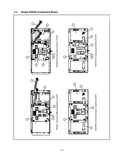
3.3 Single <strong>H50</strong>/<strong>55</strong> Component Boxes 3-3
- Page 1 and 2:
Pro H50/55-Series Gas Fryers Servic
- Page 3 and 4:
DANGER No structural material on th
- Page 5 and 6:
PRO H50/55-SERIES GAS FRYERS TABLE
- Page 7 and 8:
valve via a normally closed high-li
- Page 9 and 10:
FREQUENTLY USED TEST POINTS FOR INT
- Page 11 and 12:
4. On non-CE fryers only, place the
- Page 13 and 14:
1.6.2 Replacing the Temperature Pro
- Page 15 and 16:
1.6.5 Replacing an Ignitor Assembly
- Page 17 and 18:
6. Light the fryer in accordance wi
- Page 19 and 20:
ALL OTHER VALVES 4. Carefully unscr
- Page 21 and 22:
3. Position a container beneath the
- Page 23 and 24:
20. Remove the drain valve(s), temp
- Page 25 and 26:
To re-assemble with new insulation
- Page 27 and 28:
6 5 4 24 23 1 21 7 2 22 8 1-22 1 16
- Page 29 and 30:
valve handle appears to be in the c
- Page 31 and 32:
If these causes are ruled out, the
- Page 33 and 34:
• Shortening that remained in the
- Page 35 and 36:
the frypot until the rod loses cont
- Page 37 and 38:
The following processes will assist
- Page 39 and 40:
Heat Relay (K2 Replaceable) 2 (PWR)
- Page 41 and 42:
1. If resistance is not 5 mega-Ohms
- Page 43 and 44:
1.9.2 Wiring Diagram for Full-Vat S
- Page 45 and 46: 1.10 Principal Wiring Connections F
- Page 47 and 48: 1.11.2 Pro H50/55-Series Fryer, Sin
- Page 49 and 50: 1.11.4 Pro H50/55-Series Fryer, Sin
- Page 51 and 52: 1.11.6 Transformer/Filter Boxes 1.1
- Page 53 and 54: 1.11.6.4 FPPH 350/355 Transformer/F
- Page 55 and 56: 1.11.8 Modular Basket Lift (208/250
- Page 57 and 58: 2.1 Accessories 6 8 PRO H50/55-SERI
- Page 59 and 60: ITEM PART # COMPONENT 1 200-2942 Mo
- Page 61 and 62: ITEM PART # COMPONENT 1 Back, Singl
- Page 63 and 64: ITEM PART # COMPONENT 1 Frame, Cont
- Page 65 and 66: ITEM PART # COMPONENT 1 Frame, Cont
- Page 67 and 68: 2.5 Drain, Filtration, and Oil Retu
- Page 69 and 70: 2.5.2 Drain Valves and Associated C
- Page 71 and 72: 2.5.3 Oil Return Line Components Th
- Page 73 and 74: 2.5.4 Oil Return Handle, Oil Dispos
- Page 75 and 76: 2.5.5 Oil Disposal Wand Assembly 1
- Page 77 and 78: ITEM PART # COMPONENT 1 Valve Assem
- Page 79 and 80: 2.6 Electronics and Electrical Comp
- Page 81 and 82: 2.6.2 Transformer Boxes 15 10 34 20
- Page 83 and 84: 2.6.3 High-Limit Thermostat and Tem
- Page 85 and 86: ITEM PART # COMPONENT 1 106-1019SP
- Page 87 and 88: ITEM PART # COMPONENT 1 106-1018SP
- Page 89 and 90: ITEM PART # COMPONENT 1 Ignitor (in
- Page 91 and 92: ITEM PART # COMPONENT 1 Valve, Non-
- Page 93 and 94: Main Wiring Harnesses U.S. and Non-
- Page 95: PRO H50/55-SERIES GAS FRYERS CHAPTE
- Page 99 and 100: 3.5 Single H50/55 Transformer Boxes