Instruction Manual - Magnetrol International
Instruction Manual - Magnetrol International
Instruction Manual - Magnetrol International

You also want an ePaper? Increase the reach of your titles
YUMPU automatically turns print PDFs into web optimized ePapers that Google loves.
INTERNAL<br />
CIRCUIT<br />
(LEFT)<br />
SWITCH 4<br />
1<br />
5<br />
6<br />
2<br />
3<br />
INTERNAL<br />
CIRCUIT<br />
(RIGHT)<br />
SWITCH<br />
LOAD LOAD<br />
Close on high level (NO)<br />
Close on high level (NO)<br />
COMMON (C)<br />
COMMON (C)<br />
Close on low level (NC)<br />
Close on low level (NC)<br />
LINE<br />
LOAD<br />
LOAD<br />
LINE<br />
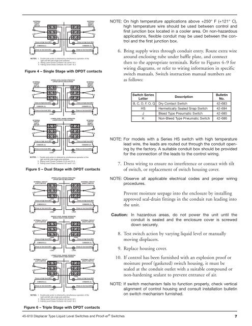
NOTES: 1. Double pole action is obtained by simultaneous operation of the<br />
right and left side single pole switches.<br />
2. Rising Level Closes Contacts 5 & 6 and 2 & 3.<br />
3. Falling Level Closes Contacts 4 & 5 and 1 & 2.<br />
Figure 4 – Single Stage with DPDT contacts<br />
INTERNAL<br />
CIRCUIT<br />
(LEFT)<br />
SWITCH<br />
INTERNAL<br />
CIRCUIT<br />
(LEFT)<br />
SWITCH<br />
UPPER LEVEL RANGE OPERATES<br />
UPPER SWITCH MECHANISM<br />
4<br />
5<br />
6<br />
4<br />
5<br />
1<br />
2<br />
3<br />
1<br />
2<br />
INTERNAL<br />
CIRCUIT<br />
(RIGHT)<br />
SWITCH<br />
LOAD LOAD<br />
Close on high level (NO)<br />
Close on high level (NO)<br />
COMMON (C)<br />
COMMON (C)<br />
Close on low level (NC)<br />
Close on low level (NC)<br />
LINE<br />
LOAD<br />
LOAD<br />
LINE<br />
LOWER LEVEL RANGE OPERATES<br />
LOWER SWITCH MECHANISM<br />
INTERNAL<br />
CIRCUIT<br />
(RIGHT)<br />
SWITCH<br />
6<br />
3<br />
LOAD LOAD<br />
Close on high level (NO)<br />
Close on high level (NO)<br />
COMMON (C)<br />
COMMON (C)<br />
Close on low level (NC)<br />
Close on low level (NC)<br />
LINE<br />
LOAD<br />
LOAD<br />
LINE<br />
NOTES: 1. Double pole action is obtained by simultaneous operation of the<br />
right and left side single pole switches.<br />
2. Rising Level Closes Contacts 5 & 6 and 2 & 3.<br />
3. Falling Level Closes Contacts 4 & 5 and 1 & 2.<br />
Figure 5 – Dual Stage with DPDT contacts<br />
INTERNAL CIRCUIT<br />
(LEFT) SWITCH<br />
UPPER LEVEL RANGE OPERATES<br />
UPPER SWITCH MECHANISM<br />
4<br />
5<br />
1<br />
2<br />
INTERNAL CIRCUIT<br />
(RIGHT) SWITCH<br />
6<br />
3<br />
LOAD LOAD<br />
Close on high level (NO)<br />
Close on high level (NO)<br />
COMMON (C)<br />
COMMON (C)<br />
Close on low level (NC)<br />
Close on low level (NC)<br />
LINE<br />
LOAD<br />
LOAD<br />
LINE<br />
MIDDLE LEVEL RANGE OPERATES<br />
MIDDLE SWITCH MECHANISM<br />
INTERNAL CIRCUIT<br />
(LEFT) SWITCH<br />
4<br />
5<br />
1<br />
2<br />
INTERNAL CIRCUIT<br />
(RIGHT) SWITCH<br />
6<br />
3<br />
LOAD LOAD<br />
Close on high level (NO)<br />
Close on high level (NO)<br />
COMMON (C)<br />
COMMON (C)<br />
Close on low level (NC)<br />
Close on low level (NC)<br />
LINE<br />
LOAD<br />
LOAD<br />
LINE<br />
LOWER LEVEL RANGE OPERATES<br />
LOWER SWITCH MECHANISM<br />
INTERNAL CIRCUIT<br />
(LEFT) SWITCH<br />
4<br />
5<br />
6<br />
1<br />
2<br />
3<br />
INTERNAL CIRCUIT<br />
(RIGHT) SWITCH<br />
LOAD LOAD<br />
Close on high level (NO)<br />
Close on high level (NO)<br />
COMMON (C)<br />
COMMON (C)<br />
Close on low level (NC)<br />
Close on low level (NC)<br />
LINE<br />
LOAD<br />
LOAD<br />
LINE<br />
NOTES: 1. Double pole action is obtained by simultaneous operation of the<br />
right and left side single pole switches.<br />
2. Rising Level Closes Contacts 5 & 6 and 2 & 3.<br />
3. Falling Level Closes Contacts 4 & 5 and 1 & 2.<br />
Figure 6 – Triple Stage with DPDT contacts<br />
NOTE: On high temperature applications above +250° F (+121° C),<br />
high temperature wire should be used between control and<br />
first junction box located in a cooler area. On non-hazardous<br />
applications, flexible conduit may be used between the control<br />
and the first junction box.<br />
6. Bring supply wires through conduit entry. Route extra wire<br />
around enclosing tube under baffle plate, and connect<br />
then to the appropriate terminals. Refer to Figures 4–9 for<br />
wiring diagrams, or refer to wiring information in specific<br />
switch manuals. Switch instruction manual numbers are<br />
as follows:<br />
Switch Series<br />
Bulletin<br />
Description<br />
Letter No.<br />
B, C, D, F, O, Q Dry Contact Switch 42-683<br />
HS Hermetically Sealed Snap Switch 42-694<br />
J Bleed Type Pneumatic Switch 42-685<br />
K Non-Bleed Type Pneumatic Switch 42-686<br />
NOTE: For models with a Series HS switch with high temperature<br />
lead wire, the leads are routed out through the conduit opening<br />
by the factory. A suitable conduit box should be provided<br />
for the connection of the leads to the control wiring.<br />
7. Dress wiring to ensure no interference or contact with tilt<br />
of switch, or replacement of switch housing cover.<br />
NOTE: Observe all applicable electrical codes and proper wiring<br />
procedures.<br />
Prevent moisture seepage into the enclosure by installing<br />
approved seal-drain fittings in the conduit run leading into<br />
the unit.<br />
Caution: In hazardous areas, do not power the unit until the<br />
conduit is sealed and the enclosure cover is screwed<br />
down securely.<br />
8. Test switch action by varying liquid level or manually<br />
moving displacers.<br />
9. Replace housing cover.<br />
10. If control has been furnished with an explosion proof or<br />
moisture proof (gasketed) switch housing, it must be<br />
sealed at the conduit outlet with a suitable compound or<br />
non-hardening sealant to prevent entrance of air.<br />
NOTE: If switch mechanism fails to function properly, check vertical<br />
alignment of control housing and consult installation bulletin<br />
on switch mechanism furnished.<br />
45-610 Displacer Type Liquid Level Switches and Proof-er ® Switches 7