Commissioning of Electrical Systems for Command, Control
Commissioning of Electrical Systems for Command, Control
Commissioning of Electrical Systems for Command, Control

Create successful ePaper yourself
Turn your PDF publications into a flip-book with our unique Google optimized e-Paper software.
TM 5-694<br />
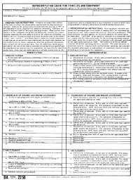
per<strong>for</strong>med in strict accordance with the drawings, systems operations documents, systems operation and<br />
maintenance manuals (provided by contractor), and the engineer’s and manufacturer’s instructions <strong>for</strong><br />
each piece <strong>of</strong> equipment. The manufacturer typically provides the instructions in the <strong>for</strong>m <strong>of</strong> diagrams<br />
indicating how to connect the test instruments as well as charts indicating acceptable and unacceptable<br />
values. The engineer’s instructions will be found in the system specifications and drawings, and the<br />
manufacturer’s instructions are found in the equipment manuals and drawings. IEEE, NEMA, National<br />
Fire Protection Association (NFPA), and other standards also include acceptable procedures <strong>for</strong> the<br />
per<strong>for</strong>mance <strong>of</strong> the tests. As the acceptance tests and energization is per<strong>for</strong>med; failures and repairs,<br />
availability <strong>of</strong> equipment and personnel, schedules, weather, and other items may cause the delay or nonper<strong>for</strong>mance<br />
<strong>of</strong> a test. In any <strong>of</strong> these cases, the missing, failed, newly required, or postponed test should<br />
be noted in the test documentation along with the reason <strong>for</strong> missing the test and the technical<br />
consequences. An evaluation should be made as to whether the system can be energized without this test<br />
noting the possible effect on safety, personnel, and equipment operation; and noting when or even if the<br />
test should be per<strong>for</strong>med in the future. If the test yet to be per<strong>for</strong>med or needs to be per<strong>for</strong>med to prove<br />
the adequacy <strong>of</strong> a repair, the test should be scheduled with the system operations personnel as part <strong>of</strong> an<br />
on-going maintenance program.<br />
(1) Field inspection and installation checks. Include inspection <strong>of</strong> impact recorders, verification <strong>of</strong><br />
removal <strong>of</strong> shipping braces, inspection <strong>of</strong> installation against drawings and nameplates, inspecting <strong>of</strong><br />
components <strong>for</strong> damage and cleanliness, inspection <strong>of</strong> insulators <strong>for</strong> cracking, inspection <strong>of</strong> anchorage<br />
and grounding, sizing check <strong>of</strong> fuses and breakers, alignment and adjustment checks, mechanical<br />
operation and interlock checks, remove CT shorting jumpers, lubrication application, verification <strong>of</strong><br />
insulating liquid or gas level or pressure, and verification that local safety equipment is in place.<br />
(2) De-energized component testing. Include pressure and level checks, megger and insulation<br />
resistance testing <strong>of</strong> equipment and connections including grounds, turns ratio measurements, polarity<br />
tests, insulating liquid dielectric and moisture testing, power factor or dissipation factor tests,<br />
overpotential tests, contact resistance measurements, operation time travel analysis, battery and cell<br />
voltage measurements, charger/UPS (uninterruptible power supply)/generator current and voltage<br />
measurements, and equipment/systems impedance or resistance tests.<br />
(3) Verification <strong>of</strong> instrument and relay operation and calibration. Include verification <strong>of</strong><br />
auxiliary device operation, calibration <strong>of</strong> instruments and relays, functional testing <strong>of</strong> individual<br />
instruments/gauges/alarms/relays/limit switches/etc.<br />
(4) Visual check <strong>of</strong> all wiring. Include visual inspection <strong>of</strong> all wiring against the schematic and<br />
wiring, both internal and external, diagrams.<br />
(5) Continuity checking <strong>of</strong> control circuits. Include continuity and voltage testing <strong>of</strong> all control<br />
circuits against schematic diagrams.<br />
(6) Energized functional testing <strong>of</strong> control circuits. Include energizing <strong>of</strong> control circuits and<br />
checking all remote and local close/trip operations, protective relay operations, safety and interlock<br />
operations, and all process and communication operations.<br />
(7) Megger testing <strong>of</strong> power circuits. Include megger testing <strong>of</strong> power, current trans<strong>for</strong>mer, and<br />
potential trans<strong>for</strong>mer buses and cables after connection.<br />
(8) Phase out testing <strong>of</strong> power circuits. Include primary and/or secondary injection testing <strong>for</strong><br />
circuit impedance and polarity checks.<br />
2-4