Commissioning of Electrical Systems for Command, Control
Commissioning of Electrical Systems for Command, Control
Commissioning of Electrical Systems for Command, Control

You also want an ePaper? Increase the reach of your titles
YUMPU automatically turns print PDFs into web optimized ePapers that Google loves.
TM 5-694<br />
be increased to compensate <strong>for</strong> the current being supplied by the charging source to the battery. Read and<br />
record the individual cell voltages and the battery terminal voltage. The readings should be taken while<br />
the load is applied at the beginning and at the completion <strong>of</strong> the test and at specified intervals. There<br />
should be a minimum <strong>of</strong> three sets <strong>of</strong> readings. Individual cell voltage readings should be taken between<br />
respective posts <strong>of</strong> like polarity <strong>of</strong> adjacent cells so as to include the voltage drop <strong>of</strong> the intercell<br />
connectors. Maintain the discharge rate and record the elapsed time at the point when the battery terminal<br />
voltage decreases to a value equal to the minimum average voltage per cell as specified by the design <strong>of</strong><br />
the installation times the number <strong>of</strong> cells.<br />
3-8<br />
b. Capacity check. The capacity <strong>of</strong> the battery is checked using the following equation:<br />
Where:<br />
Percent Capacity at the test rate at 25ºC (77ºF) = (ta / ts) x 100<br />
ta is the actual time <strong>of</strong> the test to specified terminal voltage as corrected <strong>for</strong> temperatures<br />
ts is the rated time to specified terminal voltage<br />
3-11. Battery chargers<br />
The first step towards acceptance <strong>of</strong> any device is verification <strong>of</strong> nameplate data. The nameplate on all<br />
equipment shall be checked against one-lines and schematics. All equipment shall be carefully examined<br />
upon receipt to ensure that no damage has occurred during shipment. A visual inspection should be<br />
per<strong>for</strong>med to verify the completeness <strong>of</strong> the equipment, correctness <strong>of</strong> installations, supports, grounding,<br />
and wiring. The rating plate shall be checked to ensure that both the ac supply to the charger and the<br />
battery to be connected corresponds to the charger’s parameters. Confirm that all shipping and other<br />
debris in and around the charger cabinet have been removed. Check settings <strong>of</strong> the charger and calibrate<br />
per manufacturer’s manual to match the battery (float and equalizing levels). If the battery charger has<br />
been factory set, check the charger float and equalizing voltage levels against drawings and specifications.<br />
If not, set the charger float and equalizing voltage levels to those listed on drawings and specifications.<br />
Be<strong>for</strong>e connecting to the battery, measure the output voltage provided by the charger and record. Verify<br />
that all charger functions and alarms operate correctly. Verification that the battery is connected to the<br />
battery charger properly is extremely important. The negative wire from the negative terminal <strong>of</strong> the<br />
battery must be connected to the negative terminal <strong>of</strong> the charger. Similarly, the positive wire from the<br />
positive terminal <strong>of</strong> the battery must be connected to the positive terminal <strong>of</strong> the charger. A battery<br />
charger is an electronic device that converts ac power to dc power. The charger supplies this dc power to<br />
the battery. As with all electronic devices, this device should not be megger tested.<br />
3-12. UPS systems<br />
The first step towards acceptance <strong>of</strong> any device is verification <strong>of</strong> nameplate data. The nameplate on all<br />
equipment shall be checked against one-lines and schematics. All equipment shall be carefully examined<br />
upon receipt to ensure that no damage has occurred during shipment. The Static UPS System consists <strong>of</strong><br />
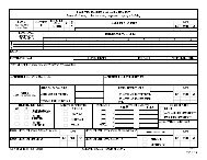
the battery charger, inverter, battery, transfer switch, circuit breakers, and cables. A picture <strong>of</strong> a typical<br />
UPS systems is seen in figure 3-1. Of the UPS system, the component testing <strong>for</strong> the battery charger,<br />
battery, transfer switch, circuit breakers, and cables are described individually in this manual. The<br />
inverter is similar in construction to the charger. It converts dc power to ac power using solid state<br />
electronics. There<strong>for</strong>e, this device should not be megger tested. The completeness <strong>of</strong> the assembly shall<br />
be confirmed. A visual inspection should be per<strong>for</strong>med to verify the correctness <strong>of</strong> installations, supports,<br />
grounding, and wiring. Verify that the air inlets are not obstructed. The interconnections shall be<br />
checked against the wiring schematic to ensure the proper phasing and voltage connections. For example,<br />
both the battery charger connections to the battery and the battery to the inverter should be checked to insure that