Commissioning of Electrical Systems for Command, Control
Commissioning of Electrical Systems for Command, Control
Commissioning of Electrical Systems for Command, Control

Create successful ePaper yourself
Turn your PDF publications into a flip-book with our unique Google optimized e-Paper software.
TM 5-694<br />
4-2. Operation <strong>of</strong> main power system<br />
Examples <strong>of</strong> operating modes <strong>for</strong> the main power system are as follows. These are some <strong>of</strong> the steps that would<br />
be included in a systems operation document (SOD). As a rule <strong>of</strong> thumb, all main power systems should be<br />
dynamically tested in all modes <strong>of</strong> operation.<br />
a. Normal condition. Both utility feeders available, both circuit switchers closed, both trans<strong>for</strong>mers<br />
energized, both switchgear breakers closed, tie breaker open, and load breakers closed.<br />
b. Abnormal condition. One utility feeder is not available. Associated circuit switcher and switchgear<br />
breaker open automatically, other circuit breaker and switchgear breaker remain closed, and tie breaker closes<br />
automatically into dead bus. Return to normal condition. Test abnormal condition again with the other utility<br />
feeder not available.<br />
c. Maintenance condition. Manually open up main circuit breaker. Corresponding circuit switcher should<br />
operate, open, and tie circuit breaker should close. Return to normal condition. Repeat procedure with other<br />
main circuit breaker and circuit switcher.<br />
NOTE: Automatic closing <strong>of</strong> the tie breaker during protective relay functions is a dead bus transfer. Manually<br />
closing <strong>of</strong> tie breaker or closing <strong>of</strong> incoming breaker with tie breaker closed will parallel both trans<strong>for</strong>mers and<br />
sync check relays will not permit breaker closing if the busses are not synchronized.<br />
4-3. <strong>Commissioning</strong> test plan <strong>for</strong> main power system<br />
A system verification and functional per<strong>for</strong>mance test should be per<strong>for</strong>med on the main power system.<br />
These tests will include installation inspections, individual component testing, verification and continuity<br />
testing on wiring, control and interlock function checks, equipment energization, system operating<br />
measurements, functional tests, and a system test under all modes <strong>of</strong> operation including the pull-the-plug<br />
test.<br />
4-4. Installation inspections and component testing <strong>of</strong> main power system<br />
The following components are part <strong>of</strong> a typical main power system. These should be inspected and tested in<br />
accordance with in<strong>for</strong>mation specified below and in chapter 3. The inspection can be considered part <strong>of</strong> prechecks<br />
and/or the functional per<strong>for</strong>mance tests (FPTs).<br />
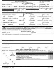
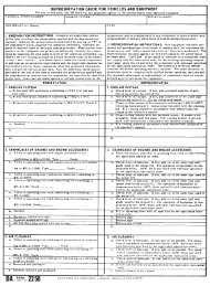
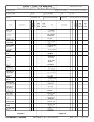
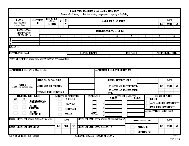
a. Circuit switcher. Verify nameplate data, sizing, and settings against drawings, completeness <strong>of</strong> assembly,<br />
loose parts and insulation damage, alignment and operation including limit switches and interlocks, insulation<br />
resistance test on each pole, interrupter time travel analysis and proper grounding. Figure 4-8 on page 4-14<br />
shows a sample <strong>of</strong> a completed DA Form 7463-R <strong>for</strong> a circuit switcher.<br />
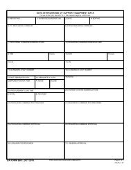
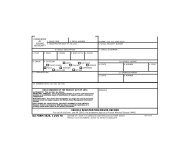
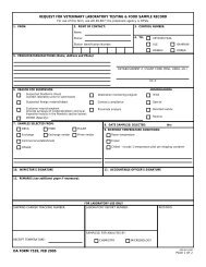
b. Oil-filled trans<strong>for</strong>mer. Verify nameplate data, size and settings against drawings, completeness <strong>of</strong><br />
assembly, loose parts and insulator damage, seals and oil levels, auxiliary device operation and settings <strong>for</strong><br />
radiators, fans, cooling, alarms, gauges, tap changer, etc., proper grounding, insulating liquid analysis <strong>for</strong><br />
dielectric breakdown, acidity, interfacial tension, power factor, color test, etc. Other tests should include<br />
insulation resistance phase-to-phase, phase-to-ground, current trans<strong>for</strong>mers, turns ratio – high-to-low windings at<br />
all taps, current trans<strong>for</strong>mers at all taps and impedance and polarity on current trans<strong>for</strong>mers. Figure 4-9 shows a<br />
sample <strong>of</strong> a completed DA Form 7464-R <strong>for</strong> a trans<strong>for</strong>mer.<br />
c. Metal clad switchgear. Verify nameplate data, sizing, and settings against drawings, completeness <strong>of</strong><br />
assembly, loose parts and insulation damage, breaker alignment and operation (leave open) including limit<br />
4-2