Chapter 3 Time-to-live Covert Channels - CAIA
Chapter 3 Time-to-live Covert Channels - CAIA
Chapter 3 Time-to-live Covert Channels - CAIA

You also want an ePaper? Increase the reach of your titles
YUMPU automatically turns print PDFs into web optimized ePapers that Google loves.
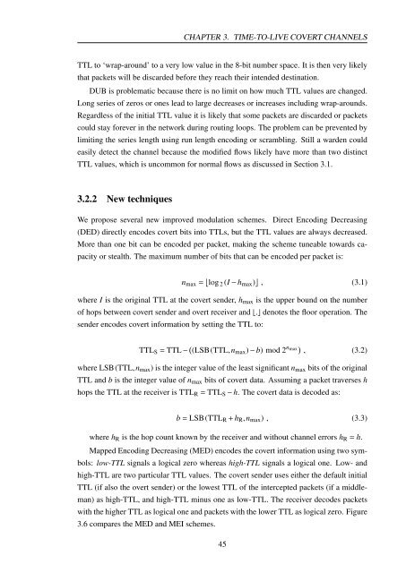
CHAPTER 3. TIME-TO-LIVE COVERT CHANNELS<br />
TTL <strong>to</strong> ‘wrap-around’ <strong>to</strong> a very low value in the 8-bit number space. It is then very likely<br />
that packets will be discarded before they reach their intended destination.<br />
DUB is problematic because there is no limit on how much TTL values are changed.<br />
Long series of zeros or ones lead <strong>to</strong> large decreases or increases including wrap-arounds.<br />
Regardless of the initial TTL value it is likely that some packets are discarded or packets<br />
could stay forever in the network during routing loops. The problem can be prevented by<br />
limiting the series length using run length encoding or scrambling. Still a warden could<br />
easily detect the channel because the modified flows likely have more than two distinct<br />
TTL values, which is uncommon for normal flows as discussed in Section 3.1.<br />
3.2.2 New techniques<br />
We propose several new improved modulation schemes. Direct Encoding Decreasing<br />
(DED) directly encodes covert bits in<strong>to</strong> TTLs, but the TTL values are always decreased.<br />
More than one bit can be encoded per packet, making the scheme tuneable <strong>to</strong>wards ca-<br />
pacity or stealth. The maximum number of bits that can be encoded per packet is:<br />
nmax = ⌊︀ log 2 (I − hmax) ⌋︀ , (3.1)<br />
where I is the original TTL at the covert sender, hmax is the upper bound on the number<br />
of hops between covert sender and overt receiver and ⌊.⌋ denotes the floor operation. The<br />
sender encodes covert information by setting the TTL <strong>to</strong>:<br />
TTLS = TTL − (︀ (LSB(TTL,nmax) − b) mod 2 nmax )︀ , (3.2)<br />
where LSB(TTL,nmax) is the integer value of the least significant nmax bits of the original<br />
TTL and b is the integer value of nmax bits of covert data. Assuming a packet traverses h<br />
hops the TTL at the receiver is TTLR = TTLS − h. The covert data is decoded as:<br />
b = LSB(TTLR + hR,nmax) , (3.3)<br />
where hR is the hop count known by the receiver and without channel errors hR = h.<br />
Mapped Encoding Decreasing (MED) encodes the covert information using two sym-<br />
bols: low-TTL signals a logical zero whereas high-TTL signals a logical one. Low- and<br />
high-TTL are two particular TTL values. The covert sender uses either the default initial<br />
TTL (if also the overt sender) or the lowest TTL of the intercepted packets (if a middle-<br />
man) as high-TTL, and high-TTL minus one as low-TTL. The receiver decodes packets<br />
with the higher TTL as logical one and packets with the lower TTL as logical zero. Figure<br />
3.6 compares the MED and MEI schemes.<br />
45