
You also want an ePaper? Increase the reach of your titles
YUMPU automatically turns print PDFs into web optimized ePapers that Google loves.
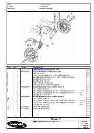
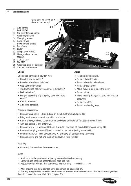
7.4 Backrestadjusting<br />
18<br />
1 Gas spring<br />
2 Fork M10x1<br />
3 Trip lever for gas spring<br />
4 Adjustment screw<br />
5 Clamping screw<br />
6 Bowden wire<br />
7 Bowden wire sleeve<br />
8 Backframe<br />
9 Clutch<br />
10 Wing screw M6x10<br />
11 Hexagon head screw<br />
M10x35<br />
12 2 discs 10,5<br />
13 Nut M10<br />
14 Adjusting lever for backrest<br />
15 Cap for bowden wire<br />
Gas spring and bowden<br />
wire compl.<br />
Check Action<br />
Check gas spring and bowden wire!<br />
• Bowden wire defective?<br />
• Bowden wire sleeve defective?<br />
• Gas spring defective?<br />
• Trip lever does not move easily or is defective?<br />
• Fork defective?<br />
• Hanger assembly of gas spring does not move<br />
easily?<br />
• Clutch defective?<br />
• Adjusting defective?<br />
> Readjust bowden wire.<br />
> Replace bowden wire.<br />
> Replace bowden wire sleeve.<br />
> Replace gas spring.<br />
> Make moving or replace trip lever<br />
> Replace fork.<br />
> Make moving hanger assembly or replace<br />
screwing.<br />
> Replace clutch.<br />
> Replace adjusting lever.<br />
Complete disassembly<br />
• Release wing screw (10) and draw off clutch (9) from backframe (8).<br />
• Bring seat system in service position and arrest.<br />
• Release hexagon head screw <strong>with</strong> nut and discs and take off fork (2) from seat frame.<br />
• Turn gas spring (1)out of fork (2).<br />
• Release screw (11) <strong>with</strong> nut (13) and discs (12) and take off clutch (9) from gas spring (1).<br />
• Release clamping screws (5) and nuts and screw out adjusting screws (4).<br />
• Pinch off caps (15) from bowden wire (6) and take off bowden wire sleeve (7).<br />
• Release screw and nut and take off trip lever(3) from fork (2).<br />
Assembly<br />
• Assembly is carried out in reverse order.<br />
3<br />
14<br />
15<br />
2<br />
4 6, 7<br />
NOTE:<br />
• Mark or note the position of adjusting screws beforedisassembly.<br />
• Screw in gas spring at assembly until stop into fork.<br />
• Adjust bowden wire so, that at screwed in gas spring??????????????????<br />
5<br />
• After drawing in a new bowden wire, caps must be squeezed on.<br />
• The adjusting lever is stored in seat frame and arrested <strong>with</strong> a starlock cap. For disassembly you first<br />
have to remove the seat shell. See chapter 7.5.<br />
4<br />
6, 7<br />
1<br />
11, 12, 13<br />
8<br />
10<br />
9