
You also want an ePaper? Increase the reach of your titles
YUMPU automatically turns print PDFs into web optimized ePapers that Google loves.
Invacare ®<br />
<strong>G40</strong> <strong>with</strong> <strong>ACS</strong>-<strong>System</strong><br />
S E R V I C E -M A N U A L<br />
The manual contains:<br />
Information on troubleshooting<br />
Information on testing parts<br />
Repair instructions<br />
Edition: 12.2001
2<br />
General information<br />
This service manual contains all information necessary for maintenance and servicing of the “<strong>G40</strong>” wheelchair.<br />
• Maintenance and servicing work is to be carried out in accordance <strong>with</strong> this service manual.<br />
• Comply <strong>with</strong> all safety instructions<br />
• Information on operation, general maintenance and servicing can be found in the operating manual of “<strong>G40</strong>”.<br />
• Refer to the replacement parts catalog for information on ordering replacement parts.<br />
• Maintenance and repair work on the “<strong>G40</strong>” may onla be performed by qualified personnel.<br />
-Maintenance technicians should at least be trained in a relevant field, e.g. as a two-wheeled vehicle or<br />
orthopaedics technician, or have an equivalent amount of professional experience.<br />
-Personnel should also be familiar <strong>with</strong> electrical measurement equipment (multimeters).<br />
• Should you encounter difficulties or have any questions, please contact INVACARE-SERVICE:<br />
Switchboard: Tel. +049 (0)5731-754-0<br />
Fax. +049 (0)5731-754-111<br />
Service: Tel. +049 (0)5731-7545-(70-80)<br />
Fax. +049 (0)5731-7542-(08-16)<br />
Adress: Invacare Deutschland GmbH<br />
Dehmer Str. 66<br />
D-32549 Bad Oeynhausen<br />
PO Box: Invacare Deutschland GmbH<br />
Postfach 60 01 06<br />
D-32 527 Bad Oeynhausen<br />
• INVACARE can not be held liable for changes to the “<strong>G40</strong>” resulting from maintenance and servicing work<br />
carried out incorrectly or not according to the relevant instructions.<br />
Information concerning transportation<br />
• If the wheelchair has to be sent away to the manufacturer for more serious repairs, always use the original<br />
packaging for transportation.<br />
• Please include a detailed account of the fault.<br />
• We reserve the right to make changes in the interests of technical progress.<br />
You will notice the following symbols in this repair manual:<br />
NOTE:<br />
This symbol indicates general information concerning special features and helpful advice for installation.<br />
ACAUTION:<br />
Please pay special attention to this symbol. It indicates<br />
>Safety instructions
1.0 Safety and installation instructions . . . . . .4<br />
2.0 List of tools . . . . . . . . . . . . . . . . . . . . . . . .5<br />
3.0 Inspection plan . . . . . . . . . . . . . . . . . . . . .6<br />
4.0 Operation troubles . . . . . . . . . . . . . . . . . . .8<br />
4.1 General instructions . . . . . . . . . . . . . . . . . .8<br />
4.2 Troubleshooting . . . . . . . . . . . . . . . . . . . . .8<br />
5.0 Error messages at remote . . . . . . . . . . . . .10<br />
5.1 Error codes of remote . . . . . . . . . . . . . . .10<br />
6.0 Arrangement of assembly groups, components<br />
and operation elements . . . . . . . . . . . . . .12<br />
7.0 Checks and repair work at seatsystem<br />
14<br />
7.1 Armrests and sides . . . . . . . . . . . . . . . . .14<br />
7.2 Legrests . . . . . . . . . . . . . . . . . . . . . . . . .15<br />
7.3 Backrest <strong>with</strong> frame, upholstery and hand<br />
grip . . . . . . . . . . . . . . . . . . . . . . . . . . . . .16<br />
7.4 Backrest adjusting . . . . . . . . . . . . . . . . . .18<br />
7.5 Seatframe, seat shell and padding . . . . .19<br />
8.0 Checks and repair work at chassis . . . . . .20<br />
8.1 Chassis covering, grips and cover coating20<br />
8.2 Wheels and tyres . . . . . . . . . . . . . . . . . . .21<br />
8.3 Back-wheel suspension . . . . . . . . . . . . . .22<br />
8.4 Front.wheel suspension . . . . . . . . . . . . . .23<br />
8.5 Handbrake . . . . . . . . . . . . . . . . . . . . . . . .24<br />
9.0 Checks and repair work at motor, gears,<br />
servo and steering . . . . . . . . . . . . . . . . . .26<br />
9.1 Driving motor and gears . . . . . . . . . . . . .26<br />
9.2 Power-assisted steering unit . . . . . . . . . .28<br />
Contents<br />
10.0 Checks and repair work at<br />
power supply<br />
10.1 Batteries, battery box and check of . . . . . .<br />
battery voltage . . . . . . . . . . . . . . . . . . . . .29<br />
10.2 Battery charging . . . . . . . . . . . . . . . . . . .30<br />
10.3 Battery charger unit . . . . . . . . . . . . . . . . .31<br />
11.0 Checks and repair work at<br />
lighting system . . . . . . . . . . . . . . . . . . . . .32<br />
11.1 Front lighting system . . . . . . . . . . . . . . .32<br />
11.2 Back lighting system . . . . . . . . . . . . . . . .33<br />
12.0 Checks and repair work at<br />
electronics . . . . . . . . . . . . . . . . . . . . . . . .34<br />
12.1 Main module . . . . . . . . . . . . . . . . . . . . . .34<br />
12.2 Remote . . . . . . . . . . . . . . . . . . . . . . . . . .35<br />
12.3 Light servo module . . . . . . . . . . . . . . . . .36<br />
12.4 Speedometer . . . . . . . . . . . . . . . . . . . . .37<br />
13.0 Continuity check of cables . . . . . . . . . . . .38<br />
14.0 Programming of wheelchair . . . . . . . . . . .39<br />
15.0 Storing of wheelchair . . . . . . . . . . . . . . . .39<br />
3
1.0 Safety and installation instructions<br />
4<br />
The safety instructions are provided in the interests of working safety and must under all circumstances be<br />
complied <strong>with</strong>.<br />
Prior to all inspection and repair work:<br />
• Read this service manual and the appertaining user manual.<br />
• Ensure that minimum qualifications for performing relevant work are fulfilled (see chapter entitled “General<br />
information”).<br />
Caution:<br />
• Note that some components are heavy. You should take this into account above all when removing<br />
the batteries.<br />
• The power supply for the wheelchair must be switched off before any conductive parts are removed.<br />
Remove the batteries.<br />
• When performing tests on conductive parts, ensure that the contacts are not short-circuited.<br />
> Danger of fire and injury from burns <<br />
• Only use tools which are in perfect working order and are not damaged.<br />
During work and assembly:<br />
• Mark the current settings of the wheelchair (seat, armrests, back etc.) and the combination of cable connections<br />
before carrying out disassembly work. This will make assembly an easier task afterwards.<br />
ACHTUNG:<br />
• Support the raised wheelchair <strong>with</strong> suitable supports before you begin assembly. Use the bottom tube<br />
. frames of the chassis. Also see the illustration <strong>G40</strong>, bottom view, chapter 6.0.<br />
• You should under no circumstances use “normal” nuts instead of self-locking nuts.<br />
• Always use correctly-sized washers or separators.<br />
Note:<br />
• All plug connectors are fitted <strong>with</strong> mechanical clamps which prevent slipping when the wheelchair is in<br />
operation.<br />
• These clamps must be pressed in to release the connectors.<br />
• When carrying out assembly work, ensure that the clamps are fitted properly.<br />
• For checks and repair works you can fold up the seat system and arrest. This position is called<br />
service position.<br />
Prior to initial use / after repair work:<br />
Caution:<br />
• Check firm mounting of all fastening screws.<br />
• Check that all parts are properly locked in place.<br />
• Check regulation tyre pressure (2.5 bar) before starting the machine.<br />
• Always perform a test-drive after repair work.
2.0 List of tools<br />
A standard toolkit comprising the following minimum inventory is required:<br />
Combination ring and open-end spanner SW 6, 7, 8, 10, 11, 12, 13, 17, 19<br />
Allan key 2,5 mm, 3mm, 4mm, 5 mm, 6 mm, 8mm, 10mm<br />
Torque wrench (commercially available)<br />
Socket spanner set<br />
Screwdrivers for slotted screws various<br />
Crosstip screwdriver No.1, No.2<br />
Side-cutting pliers<br />
Flat pliers<br />
Round pliers<br />
Cable lug pliers<br />
Wooden or plastic hammer<br />
Tyre repair set (commercially available)<br />
Air pressure gauge<br />
Valve extraction tools<br />
Special tool for removing wheel bearing<br />
Multimeter <strong>with</strong> test points and various cable clips<br />
Bridging cable<br />
Soldering iron 30W<br />
Assembly pliers for Starlock caps (commercially available)<br />
Removing tools for font wheel hub (available by INVACARE-Service)<br />
You will require the following for setting at the <strong>ACS</strong> control:<br />
Programming unit Item no.<br />
Software package, incl. interface cable and dongle Item no.<br />
5
3.0 Inspecton plan<br />
6<br />
Component<br />
Armrests and sides<br />
Check<br />
• Damage to and attachment<br />
of armrests<br />
• Damage to and attachment<br />
of side panels<br />
• Mirrors<br />
Action<br />
> Tighten screws. Replace<br />
overlay.<br />
> Tighten screws. Replace<br />
sides.<br />
> Replace.<br />
Seat • Damage and screw<br />
> Tighten screws. Repla-<br />
fastenings, stitching<br />
ce parts.<br />
Backrest <strong>with</strong> safety<br />
belt<br />
Latching mechanism<br />
of seat in service<br />
position<br />
Chassis <strong>with</strong> frame,<br />
side grips and covering<br />
Wheel suspension and<br />
wheels<br />
• Adjustment function<br />
• Damage and screw<br />
fastenings, stitching<br />
• Belt and belt buckle<br />
• Damage and secure latching<br />
into place<br />
• Screw attachments, welded<br />
joints, damages<br />
• Function and damage of<br />
shock absorbers<br />
• Wheel suspension<br />
• Wheel bearing<br />
• Tyre equipment<br />
> Adjust or replacebowden<br />
wire, gas spring.<br />
> Tighten screws. Replace<br />
parts.<br />
> Replace.<br />
> Make moving<br />
> Tighten screws.<br />
Replace parts.<br />
> Tighten, replace.<br />
> Replace.<br />
> Replace.<br />
> Adjust, replace.<br />
> Fit on new ones.<br />
Hand brake • Function<br />
> Adjust, replace.<br />
Drive and steering<br />
asssembly<br />
• Loose bowden wires, sleeves<br />
damaged<br />
• Wear, damage of brake<br />
discs and brake calipers<br />
• Check function in driving<br />
and freewheel operation<br />
• Check toggle link<br />
> Tighten, adjust,<br />
replace.<br />
> Replace.<br />
> Adjust, replace.<br />
> Adjust, replace.<br />
Legrests • Welded joint, lock, screw<br />
attachment<br />
> Tighten, replace.<br />
• Footboard<br />
> Tighten, replace.<br />
Chapter<br />
7.1<br />
7.5<br />
7.3<br />
7.5<br />
8.1<br />
8.2<br />
bis<br />
8.4<br />
8.5<br />
9.0<br />
7.2<br />
!
Component<br />
Batteries<br />
Light-servo module<br />
and lighting system<br />
Drive electronic and<br />
main module<br />
Drive electronic<br />
Remote<br />
Check<br />
• Damage of battery and<br />
box, corrosion on<br />
contacts<br />
• Check of contacts and<br />
pole clips<br />
• Check battery voltage<br />
• Function servo- and light<br />
module<br />
• Damage of lights<br />
• Function of light bulbs<br />
• Status display flashes<br />
• Voltage supply<br />
• Attachment<br />
• Cables, plug connections<br />
• Function joystick<br />
• Voltage supply<br />
Action<br />
> Clean contacts, replace<br />
battery or box<br />
> Tighten, replace.<br />
> Charge battery, replace.<br />
> Replace cable, connector<br />
or module.<br />
> Replace lights.<br />
> Replace light bulbs.<br />
> Replace module.<br />
> Replace cable, connector<br />
or module.<br />
> Tighten, replace.<br />
> Replace.<br />
> Replace remote.<br />
> Replace cable, connector<br />
or panel.<br />
Speedometer • Check function<br />
> Replace batteries, cable,<br />
connector, speedometer or<br />
sensor.<br />
Chapter<br />
10.1<br />
bis<br />
10.2<br />
12.3<br />
und<br />
11.0<br />
12.1<br />
12.2<br />
12.4<br />
!<br />
7
4.0 Operation troubles<br />
4.1 General instructions<br />
Do the following if there are any troubles in driving mode, at lighting system or power supply:<br />
• Analyze the in 4.2 described troubleshooting.<br />
• Check the status display at remote and analyze the error codes like in chapter 5.1.<br />
• Do the required checks / repair work. Note the cross references in the appertaining chapters in the manual or<br />
in the appertaining documentation.<br />
4.2 Troubleshooting<br />
Störungen<br />
8<br />
Wheelchair doesn´t drive<br />
Drive motor / steering<br />
servo motor disengaged<br />
Status display at<br />
remote off<br />
Status display at<br />
remote flashes<br />
Microswitch defective<br />
(nur TÜV-Version 10 km/h)<br />
Drive motor runs in a jerky manner<br />
Motor defective<br />
Incorrect programming<br />
Battery defective<br />
Battery deep<br />
discharged<br />
Power supply<br />
interrupted<br />
Engage motors<br />
Replace battery<br />
Pre-charge battery<br />
check overload<br />
protector<br />
check voltage at<br />
remote<br />
check voltage at<br />
main module<br />
Error code 1 - 12 Check error code<br />
Check microswitch<br />
Replace motor<br />
Check programming<br />
Chapter 6.0<br />
Chapter 10.1<br />
Chapter 10.2<br />
not correct<br />
Chapter 12.2<br />
Chapter 12.1<br />
Chapter 5<br />
not correct<br />
Chapter 9.1<br />
Manual for programming<br />
unit or<br />
PCD-software
Störungen<br />
Steering servo motor reacts slowly /<br />
irregularly<br />
Motor defective<br />
Incorrect programming<br />
Light-/servo module<br />
defective<br />
Status display flashes, after 4 sec. the<br />
driving mode display also flashes<br />
Joystick not in<br />
neutral position<br />
when switch on<br />
Replace motor<br />
Check programming<br />
Switch remote off<br />
and on<br />
Remote defective Replace remote<br />
Lighting system defective<br />
Light bulb defective<br />
Cable / connector<br />
defective<br />
Light-/servo module<br />
defective<br />
Charging batteries impossible<br />
Battery defective<br />
Charging unit<br />
defective<br />
Replace light-<br />
/servo module<br />
Replace light bulb<br />
Check / replace<br />
cable / connector<br />
Replace light-<br />
/servo module<br />
Replace battery<br />
Replace charging<br />
unit<br />
Chapter 9.1<br />
Manual for programming<br />
unit or<br />
PCD-software<br />
Chapter 12.3<br />
Chapter 12.2<br />
Chapter 12.2<br />
Chapterl 11.1/11.2<br />
Chapter 11.1/11.2<br />
Chapter 12.3<br />
chapter 10.1<br />
Chapter 10.3<br />
Signal horn defective Replace remote Chapter 12.2<br />
Speedometer defective<br />
Replace speedometer<br />
Chapter 12.4<br />
9
5.0 Error messages at remote<br />
5.1 Error codes of remote<br />
10<br />
The following error codes refer to the <strong>G40</strong> standard model <strong>with</strong> remote, main module and servo-/light module.<br />
Do the follwing check before analyzing the error codes:<br />
• Switch on and off the remote several times.<br />
Wait five sec. before switching on again.<br />
This check determines whether the error can automatically be corrected by the electronic system in which case<br />
the flashing of status display is automatically deactivated.<br />
If this is not the case, localize the error <strong>with</strong> the flash code.<br />
Flash codes on remote status display:<br />
1 x flash Elektronic module defective<br />
2 x flashes<br />
Steering servo disengaged<br />
5 x flashes Motor connection loose/defective<br />
6 x flashes<br />
Cable/connector loose, defective<br />
Servo-/light module defective<br />
Back turn signal bulb defective **<br />
Short circuit in Lighting system<br />
Check / replace status display of<br />
modules<br />
Engage servo (Driving mode)<br />
Check/replace connector/cable<br />
Replace servo-/light module<br />
Steering servo motor defective Check/replace servo motor<br />
Replace turn signal bulb<br />
Check lighting system<br />
3 x flashes Drive motor disengaged* Engage motor (Driving mode)<br />
4 x flashes Motor connection loose/defective Check/replace cable/connector<br />
Drive motor defective Check/replace motor<br />
Check/replace cable/connector<br />
Drive motor defective Check/replace motor<br />
Motor connection loose/defective Check/replace cable/connector<br />
Brake error at motor Check motor brake<br />
Check/replace motor<br />
* Flash code can only be activated when you move the joystick in freewheel operation.<br />
** Flash code can only be activated when the turn signal is also switched on.<br />
The flash codes can be generally deactivated by switching off and on at remote.<br />
Chapter 12.0<br />
Chapter 9.2<br />
Chapter 13.0<br />
Chapter 12.3<br />
Chapter 9.2<br />
Chapter 11.2<br />
Chapter 11.0<br />
Chapter 9.1<br />
Chapter 19.0<br />
Chapter 9.1<br />
Chapter 13.0<br />
Chapter 9.1<br />
Chapter 9.1<br />
Chapter 9.1<br />
Chapter 9.1
7 x flashes Battery deep discharged<br />
8 x flashes Battery voltage too high<br />
9 x flashes Incorrect data transfer between<br />
the modules<br />
10 x flashes<br />
11 x flashes<br />
12 x flashes<br />
Power-assisted steering- or<br />
drive motor overloaded<br />
Compatibilityproblems between<br />
the modules<br />
Charge batteries<br />
Check charging unit<br />
Check modules and Programming,<br />
inform INVACARE-service<br />
Switch off and on the remote<br />
Repair by INVACARE-service<br />
necessary<br />
Chapter 10.2<br />
Chapter 10.3<br />
Chapter 14.0<br />
11
6.0 Arrangement of assemblies, components and features<br />
12<br />
The following illustrations show the arrangement of the main assemblies, components and features for righthanded<br />
people. The terms are the same as the component terms in the replacement parts catalog.<br />
1 Leg rests complete, appertaining to seat<br />
system<br />
2 Chassiscovering<br />
3 Seat shell, appertaining to seat system<br />
4 Seat padding, appertaining to seat system<br />
5 Back padding, appertaining to seat system<br />
6 Mirror<br />
7 Front lighting system, integrated in<br />
seat shell<br />
8 Front wheels, powered<br />
9 Back wheel, steerable<br />
12<br />
21<br />
10<br />
15<br />
11<br />
9<br />
<strong>G40</strong>, side view<br />
14<br />
13<br />
20<br />
2<br />
19<br />
18<br />
16<br />
17<br />
8<br />
<strong>G40</strong>, front view<br />
8<br />
7<br />
1<br />
2<br />
3<br />
1<br />
4<br />
10 Frame <strong>with</strong> back shell 11 and grip<br />
grip 12<br />
13 Sides complete <strong>with</strong> arm rests<br />
14 Side grip<br />
15 Covering<br />
5<br />
16 Remote <strong>with</strong> speedometer<br />
17 Hand brake complete <strong>with</strong> brake<br />
disc 18<br />
8<br />
19 Back rest adjusting, complete<br />
20 Walking stick holder<br />
21 Walking stick loop<br />
7<br />
9<br />
6
1 Chassis (Tube frame back, bottom)<br />
2 Seat frame, appertaining to seat system<br />
3 Seat shell <strong>with</strong> indentations for electronic<br />
modules<br />
4 Locking mechanism of seat support for<br />
service<br />
5 Locking mechanism of seat in closed<br />
position<br />
6 Gas spring for back rest adjusting<br />
7 Batteries in battery box<br />
8 Battery box<br />
9 Cable form for drive motor<br />
<strong>G40</strong>, back view<br />
12<br />
1<br />
12<br />
14<br />
14<br />
13 13<br />
15<br />
15 Disengaging lever for servo motor<br />
16 Gear box <strong>with</strong> front axle<br />
17 Drive motor, flange mounted to gear box<br />
18 Main module of drive electronics<br />
19 Servo steering <strong>with</strong> motor<br />
20 Wheel suspension, back<br />
2<br />
<strong>G40</strong>, service view<br />
5<br />
11<br />
3<br />
9<br />
8<br />
10<br />
7<br />
10 Disengaging lever for drive motor<br />
11 Cable form for servo-/light module<br />
12 Lighting system back, integrated in chassis<br />
6<br />
13 Shock absorbers, back<br />
14 Steering rod, appertaining to power-assisted<br />
steering<br />
<strong>G40</strong>, bottom view<br />
1<br />
17<br />
8<br />
1<br />
18<br />
19<br />
16<br />
7<br />
3<br />
20 20<br />
4<br />
2<br />
13
7.0 Checks and repair work at seat system<br />
7.1 Arm rests and sides<br />
14<br />
Right side, complete Left side, complete<br />
1<br />
2<br />
12, 11<br />
6<br />
9<br />
Check Action<br />
5<br />
1 Arm rest tube frame 2 Arm rest<br />
3 Side covering 4 Bag (not illustrated)<br />
5 Side mount 6 Clip lever M8x60<br />
7 Mirror 8 Wing screw M6x10<br />
9 Hexagon head screw M6x16 10 Nut M8, self locking <strong>with</strong> cap<br />
11 Hexagon head screw M5x35 12 Disc 5,4<br />
13 Nut M8<br />
• Arm rest damaged?<br />
• Screws of arm rest loose?<br />
• Bag damaged?<br />
• Side covering damaged?<br />
• Arm rest tube frame damaged?<br />
• Side mount damaged?<br />
• Clip lever damaged?<br />
• Mirror damaged?<br />
NOTE:<br />
8<br />
3<br />
1<br />
2<br />
12, 11<br />
6<br />
> Replace arm rest.<br />
> Tighten screws.<br />
> Replace bag.<br />
> Replace side covering.<br />
> Replace arm rest tube frame.<br />
> Replace side mount.<br />
> Replace clip lever.<br />
> Replace mirror.<br />
If there´s an arm rest <strong>with</strong> integrated remote:<br />
Switch off wheelchair, take plug out of remote, release remote and take it out of arm rest.<br />
Complete disassembly<br />
• Bring seat system in service position and arrest.<br />
• Release wing screw (8) and draw off sides <strong>with</strong> arm rest sideways away from chassis.<br />
• Release clip lever and draw off side mount downwards.<br />
• Release bag (4) from side covering (3) (velcro fastener).<br />
• Release screws (11) <strong>with</strong> discs (12) at side covering and draw off arm rest (2).<br />
• Release plastic rivets at bottom of side covering <strong>with</strong> a screw driver and draw off side covering (3)<br />
from arm rest tube frame.<br />
• Remove cap, release nut (10) and draw off mirror (7) out of arm rest tube frame (1).<br />
Assembly<br />
• The assembly is carried out in reverse order.<br />
13<br />
5<br />
7<br />
10
7.2 Legrests<br />
6<br />
4<br />
Legrests compl. 22<br />
Legrest<br />
Parts<br />
6<br />
1<br />
1<br />
11 2<br />
6<br />
12<br />
5<br />
8<br />
10<br />
4<br />
2<br />
1 Legrest, top 2 Insertion tube 3 Footplate mount<br />
4 Footplate 5 Calfsupport holder 6 Calfsupport<br />
7 Calf pad mount 8 Calfsupport pivot 9 2 Plastic discs 17x6,5<br />
10 Clamping lever M6x10 11 Hexagon head screw M6x10 12 Fillister-head screw M6x16<br />
13 Countersunk screw M5x25 14 Nut M5 (self locking) 15 Screw M6x45<br />
16 Nut M6 17 Nut M8 18 Disc 8,4<br />
19 Fillister-head self-tapping screw 20 Hat nut M6 21 Slide SL 18<br />
22 Slide F30x15 23 Clamping sleeve 5x20 (Not shown, belongs to 7 and 8.)<br />
Check Action<br />
• Screws loose?<br />
• Calfsupport damaged?<br />
• Footplate damaged?<br />
• Footplate mount damaged?<br />
• Welded joints or insertion tube defective?<br />
• Welded joints or top legrest defective?<br />
• Calfsupport pivot goes heavily, defective?<br />
• Slides missing or damaged?<br />
9<br />
2<br />
20<br />
3<br />
17<br />
18<br />
19<br />
15,16 21<br />
> Tighten screws.<br />
> Replace calfsupport.<br />
> Replace footplate.<br />
> Replace footplate mount.<br />
> Replace insertion tube.<br />
> Replace top of legrest.<br />
> Make pivot moving or replace.<br />
> Replace slide.<br />
Complete disassembly:<br />
• Bring seat system in service position and arrest.<br />
• Release clamping lever (10) and draw off legrest from chassis.<br />
• Release hexagon head screw und draw off top of legrest from insertion tube.<br />
• Release fillister-head screwand draw off calfsupport.<br />
• Release countersunk screws (13 and nuts (14) and remove calf pad mount(7).<br />
• Remove nut (17) and disc (18)and remove calfsupport holder (5) from pivot (8).<br />
• Remove clamping sleeve (23) and remove calfsupport pivot (8) from clip part (7).<br />
• Remove tin screws (19) and draw off footplate (4) from footplate mount.<br />
• Remove screw (15) <strong>with</strong> hatnut (20) and discs (9) and draw off footplate mount from insertion tube.<br />
• Release slide (21/22) from footplate mount/top of legrest <strong>with</strong> a screwdriver.<br />
Assembly<br />
• Assembly is carried out in reverse order.<br />
NOTE:<br />
• The screw (15) <strong>with</strong> nut (16) serves for adjusting of footplate.<br />
• Don´t tighten the screw (15) <strong>with</strong> hatnut (20) and nut (17) too strong.<br />
7<br />
4<br />
13<br />
14<br />
15
7.3 Backrest <strong>with</strong> frame, padding and grip<br />
16<br />
Backrest, front view, <strong>with</strong>out padding Backrest, back view<br />
14<br />
15<br />
13<br />
2<br />
2<br />
1<br />
3, 4, 5, 16<br />
15<br />
10<br />
11, 12<br />
7, 8<br />
1 Back shell 2 Backframe<br />
3 Backmount socket 4 Starlock caps 16,0<br />
5 Disc 17,0 6 Backpadding (not shown)<br />
7 Clutch part for gas spring 8 Wing screw M6x10<br />
9 Safety belt (not shown) 10 Mounting plate for safety belt<br />
11 Hexagon head screw M6x20 12 Disc 6,4<br />
13 Threaded bolt M6x6 14 Walking stick loop<br />
15 Grip 16 Chassis<br />
Check Action<br />
• Backpadding damaged?<br />
• Screws at backframe loose?<br />
Backshell damaged?<br />
• Backframe damaged, welded joints<br />
defective?<br />
• Grip damaged?<br />
• Walking stick loop damaged?<br />
• Safety belt damaged?<br />
• Backframe does not go easily?<br />
> Replace backpadding.<br />
> Tighten screws.<br />
> Replace back shell.<br />
1<br />
10<br />
> Replace backframe.<br />
> Replace grip.<br />
> Replace walking stick holder.<br />
> Replace safety belt.<br />
> Make moving or replace backmount socket.<br />
Complete disassembly:<br />
• Draw off backpadding from seat shell (velcro fasteners).<br />
• Release crosstip screw and remove walking stick loop (14).<br />
• Release threaded bolts (13) and pull out grip (15).<br />
• Release wing screw (8) and pull out clutch part from backframe (2) downwards.<br />
• Release hexagon head screws (11) <strong>with</strong> discs (12) and remove safety belt (9) <strong>with</strong> mounting plate (10).<br />
• Pull out backshell (1) from backframe (2) downwards.<br />
• Note position of discs (5).<br />
• Release starlock caps (4) <strong>with</strong> a flat screwdriver and remove backmount socket (3) <strong>with</strong> discs (5).<br />
• Remove backframe (2) from chassis.
Assembly<br />
• Assembly is carried out in reverse order.<br />
NOTE:<br />
• Use new starlock caps (4) for assembly.<br />
• During assembly of backframe (2) take care, that the discs (5) are pushed into the backmount socket<br />
in right order.<br />
For assembly of backframe at chassis do the following:<br />
• Positon chassis, back- and side frame so, that you can insert backmount socket (3) <strong>with</strong> discs.<br />
• Put in the starlock caps into the pliers as you can see below.<br />
• Position pliers <strong>with</strong> caps (4) on both sides on the backmount socket and tighten.<br />
• Tighten pliers <strong>with</strong> a ring spanner until the caps are completely pressed on.<br />
• Release starlock pliers and take off.<br />
• Complete assembly of backrest.<br />
Starlock pliers <strong>with</strong> caps Insertion of caps<br />
4<br />
17
7.4 Backrestadjusting<br />
18<br />
1 Gas spring<br />
2 Fork M10x1<br />
3 Trip lever for gas spring<br />
4 Adjustment screw<br />
5 Clamping screw<br />
6 Bowden wire<br />
7 Bowden wire sleeve<br />
8 Backframe<br />
9 Clutch<br />
10 Wing screw M6x10<br />
11 Hexagon head screw<br />
M10x35<br />
12 2 discs 10,5<br />
13 Nut M10<br />
14 Adjusting lever for backrest<br />
15 Cap for bowden wire<br />
Gas spring and bowden<br />
wire compl.<br />
Check Action<br />
Check gas spring and bowden wire!<br />
• Bowden wire defective?<br />
• Bowden wire sleeve defective?<br />
• Gas spring defective?<br />
• Trip lever does not move easily or is defective?<br />
• Fork defective?<br />
• Hanger assembly of gas spring does not move<br />
easily?<br />
• Clutch defective?<br />
• Adjusting defective?<br />
> Readjust bowden wire.<br />
> Replace bowden wire.<br />
> Replace bowden wire sleeve.<br />
> Replace gas spring.<br />
> Make moving or replace trip lever<br />
> Replace fork.<br />
> Make moving hanger assembly or replace<br />
screwing.<br />
> Replace clutch.<br />
> Replace adjusting lever.<br />
Complete disassembly<br />
• Release wing screw (10) and draw off clutch (9) from backframe (8).<br />
• Bring seat system in service position and arrest.<br />
• Release hexagon head screw <strong>with</strong> nut and discs and take off fork (2) from seat frame.<br />
• Turn gas spring (1)out of fork (2).<br />
• Release screw (11) <strong>with</strong> nut (13) and discs (12) and take off clutch (9) from gas spring (1).<br />
• Release clamping screws (5) and nuts and screw out adjusting screws (4).<br />
• Pinch off caps (15) from bowden wire (6) and take off bowden wire sleeve (7).<br />
• Release screw and nut and take off trip lever(3) from fork (2).<br />
Assembly<br />
• Assembly is carried out in reverse order.<br />
3<br />
14<br />
15<br />
2<br />
4 6, 7<br />
NOTE:<br />
• Mark or note the position of adjusting screws beforedisassembly.<br />
• Screw in gas spring at assembly until stop into fork.<br />
• Adjust bowden wire so, that at screwed in gas spring??????????????????<br />
5<br />
• After drawing in a new bowden wire, caps must be squeezed on.<br />
• The adjusting lever is stored in seat frame and arrested <strong>with</strong> a starlock cap. For disassembly you first<br />
have to remove the seat shell. See chapter 7.5.<br />
4<br />
6, 7<br />
1<br />
11, 12, 13<br />
8<br />
10<br />
9
7.5 Seatframe, seat shell and padding<br />
Seatframe Seat shell<br />
1<br />
Check Action<br />
• Padding damaged?<br />
• Seat shell damaged?<br />
• Seatframe warped or<br />
welded joints defective?<br />
• Screwed connections of latching<br />
mechanism loose?<br />
• Latching mechanism warped<br />
or defective?<br />
Complete disassembly<br />
• Remove backframe and backshell. See chapter 7.3.<br />
• Secure frame (1) <strong>with</strong> sockets and remove padding (3) from seat shell (2) (velcro fasteners).<br />
• Release plug from light-/servomodule and take module out of seat shell (2).<br />
• Bring seat in service position and fix it.<br />
• Take off gas spring from seat frame and release bowden wire from gas spring.<br />
• Remove plastic rivets <strong>with</strong> a screw driver and take off the front lighting carefully out of seat shell downwards.<br />
• Draw off plug from connector row (6), remove cable connector, disengage lighting cable carefully and<br />
remove lamps completely.<br />
• Release screws from seat support and remove both parts of support from seatframe (1).<br />
• Remove securing socket again and take off frame (1) <strong>with</strong> seat shell (2) from chassis.<br />
• Press seat shell (2) at front and sides carefully outwards and take off from frame (1).<br />
Assembly<br />
• Assembly is carried out in reverse order.<br />
1<br />
6<br />
5<br />
4<br />
2<br />
1 Seatframe 2 Seat shell<br />
3 Padding (not shown) 4 Latching mechanism<br />
5 Front lighting equipment, compl. 6 Connector row for lighting system<br />
> Replace padding.<br />
> Replace seat shell.<br />
> Straighten frame.<br />
> Replace frame.<br />
> Tighten screws.<br />
> Straighten or replace.<br />
Light-/servo module<br />
NOTE:<br />
• Take care during disassembly / assembly that the cable forms to the front lighting,<br />
to light-/servomodule and to remote run freely and aren´t damaged.<br />
• Before disassembly of seatframe and seat shell you first have to remove backframe and backshell.<br />
After that secure seatframe <strong>with</strong> fitting sockets at chassis.<br />
2<br />
19
8.0 Checks and repair work at chassis<br />
8.1 Chassiscovering, grips and cover coating<br />
20<br />
Chassiscovering Side grip<br />
3<br />
8<br />
Check Action<br />
• Cover coating loose or damaged?<br />
• Side grip or rosette damaged?<br />
• Chassiscovering damaged?<br />
• Stick holder damaged?<br />
Disassembly side grip<br />
• Bring seat system in service position and arrest.<br />
• Remove caps (9), remove hexagon head screws (10) <strong>with</strong> discs (11) and take off grip (2) <strong>with</strong> rosettes<br />
(4).<br />
Assembly<br />
• Assembly is carried out in reverse order.<br />
1<br />
4<br />
2<br />
5<br />
disassembly chassiscovering<br />
6<br />
7<br />
2<br />
9, 10, 11<br />
1 Chassiscovering 2 Side grip 3 Cover coating<br />
4 Rosettes 5 Stick holderr 6 Plastic rivet<br />
7 Brake lever 8 Wing screw M6x10 9 Cap SKS 8<br />
10 Hexagon head screw 11 Securing disc Schnorr M8<br />
NOTE:<br />
> Stick or replace coating.<br />
> Replace side grip or rosette.<br />
> Replace chassiscovering.<br />
> Replace stick holder.<br />
9, 10, 11<br />
Before thedisassembly of chassiscovering you first must disassemble the seat system completely.<br />
See chapter 7.1 to 7.5.<br />
• Remove hexagon head screws <strong>with</strong> nuts and take off stick holder (5).<br />
• Release wing screw (8) and take off brake lever (7).<br />
• Remove side grips (2) <strong>with</strong> rosettes (4).<br />
• Remove the eight plastic rivets (6), two at sides, two at front, two at back.<br />
For doing that you first must draw off the pins (in covering) <strong>with</strong> pliers out of the rivets.Then remove the<br />
rivets from outside <strong>with</strong> a screwdriver.<br />
• Take off chassiscovering from chassis upwards.<br />
Assembly<br />
• Assembly is carried out in reverse order.
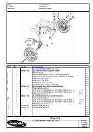
8.2 Wheels and tyres<br />
NOTE:<br />
• Back and front wheels are all fixed <strong>with</strong> four countersunk<br />
screws on the wheel hubs.<br />
• Construction of rims is equal.<br />
• Because of that the disassembly is identical.<br />
1 Front wheel, compl. 7 Back wheel, compl.<br />
2 Rim (part 1) <strong>with</strong> 3 (part2) 8 Rim (part 1) <strong>with</strong> 9 (part 2)<br />
4 Tyre casing <strong>with</strong> tube 5 10 Tyre casing <strong>with</strong> tube 11<br />
6 Countersunk screw <strong>with</strong> - 12 Had cap screw <strong>with</strong> hexa<br />
hexagon socket<br />
Check Action<br />
• Tyre looses air?<br />
• Tyre casing damaged?<br />
• Screws loose?<br />
• Rims damaged??<br />
> Repair or replace tube.<br />
> Check casing on<br />
foreign substance.<br />
> Replace tyre casing.<br />
> Tighten screws.<br />
> Replace rims.<br />
Back wheel,<br />
disassembled<br />
Complete disassembly<br />
• Release countersunk screws (6) crosswise.<br />
• Prop up wheel chair, so that the wheel is free.<br />
• Screw out countersunk screws (6) completely and take off wheel (1or7).<br />
• Let out air, release head screw (12) crosswise and remove.<br />
• Disassemble rim (part1, part 2).<br />
• Remove tube out of tyre casing.<br />
• Repair or renew tube (size 3.00-10 front, 3.00-8 back).<br />
Assembly<br />
• Fill in little air until tube is round.<br />
• Put tube in tyre casing and put in both rim halfs from outside into casing.<br />
CAUTION:<br />
• The recesses of rim halfs must surround the valve.<br />
• The tube must not be squeezed between the rim halfs.<br />
7<br />
6<br />
2, 3<br />
8, 9<br />
• Put in head screw (12), drive in crosswise and tighten <strong>with</strong> torque wrench (25 to 30 Nm).<br />
• Pump up tyre to a pressure of 2,5 bar and screw on valvecap.<br />
• Put wheel on hub, set in countersunk screws (6) and tighten crosswise <strong>with</strong> 25 Nm.<br />
CAUTION:<br />
12<br />
Front wheel,<br />
assembled<br />
• The countersunk screws (6) must not be greased.<br />
• During factory assembly the screws are set in <strong>with</strong> plasbolt. They can be assembled / disassembled<br />
up to 6 times.<br />
• At the latest screws must be cleaned during 7. assembly and then set in <strong>with</strong> Loctite.<br />
• Tighten screws <strong>with</strong> 25 Nm.<br />
1<br />
4<br />
5<br />
10<br />
11<br />
21
8.3 Wheel suspension back<br />
22<br />
NOTE:<br />
• Change or repair of steering column (4) must be<br />
done by INVACARE-service.<br />
1 Shock absorber, soft 2 Stub axle<br />
3 floating socket 4 Steering column<br />
in steering column 5 Head screw M12x120<br />
6 Nut M12 7 Disc 13,0<br />
8 Wheel hub 9 Socket (in hub)<br />
10 Ball bearing 6001ZZ 11 Nut M8<br />
(in hub)) 12 Disc 8,4<br />
13 Telescopic spring mount 14 Screw M8x55<br />
15 Head screw M8x35 16 Stopper SL35<br />
17 Securing disc M8 (not shown)<br />
(13, 15 and 17 top<br />
at steering column))<br />
Check Action<br />
• Shock absorber defective?<br />
• Screwings loose?<br />
• Wheel does not run easily?<br />
Hub damaged?<br />
Stub axle defective?<br />
> Replace shock absorber.<br />
> Tighten screws.<br />
> Replace wheel bearing.<br />
> Replace hub.<br />
> Replace stub axle.<br />
14<br />
12<br />
11<br />
Disasssembly shock absorber<br />
• Prop up wheel chair so that shock absorber is accessible.<br />
• Remove screw (15) <strong>with</strong> disc (17) from telescopic spring mount (13).<br />
• Remove screw (14) <strong>with</strong> nut (11) and disc (12) and take off shock absorber.<br />
Assembly<br />
• Assembly is carried out in reverse order.<br />
Wheel suspension back<br />
4<br />
1<br />
8<br />
6<br />
7<br />
2<br />
5, 7<br />
13, 15<br />
17<br />
4<br />
9, 10<br />
Disassembly of stub axle and wheel hub<br />
• Disassemble back wheel. See chapter 8.2.<br />
• Disassemble shock absorber. See above.<br />
• Remove nuts (6) and discs (7) from floating socket (3).<br />
• Screw out screw (5) out of stub axle (2) and remove <strong>with</strong> disc (7) from steering column.<br />
• Take off stub axle (2) <strong>with</strong> wheel hub (8) from steering column (4).<br />
• Remove stopper (16) from wheel hub (8).<br />
• Remove nut (6) <strong>with</strong> disc (7), draw off screw (5) <strong>with</strong> disc (7) out of wheel hub (8) and take wheel hub from<br />
stub axle (2).<br />
• Remove ball bearing (10) <strong>with</strong> a special tool out of hub (8) and remove socket (9).<br />
Assembly<br />
• Assembly is carried out in reverse order.<br />
NOTE:<br />
• Before set in ball bearing (10) you must set in the socket (9).<br />
• Do not cant bearing during pressing in.<br />
• Do not forget floating socket (3) during assembly of stub axle.<br />
• Do not forget discs and stick on in right order.<br />
• Hold up nuts (6) during assembly.<br />
6<br />
7<br />
3<br />
5, 7
8.4 Wheel suspension front<br />
NOTE:<br />
• Change or repair of front axle (5), gear rocker arm<br />
(2) and all components appertaining to gear must<br />
be done by INVACARE-service.<br />
1 Shock absorber, hard 2 Gear rocker arm<br />
3 Wheel hub 4 Brake disc 160x2<br />
5 Front axle, compl.. 6 Bowden wire, compl..<br />
7 Brake caliper, compl.. 8 Cable socket<br />
9 Roundmagnet 625-6.0 10 Mounting for sensor<br />
(for speedometer sensor) (<strong>with</strong> speedom. sensor<br />
11 Head screw M6x12 12 Head screw. M8x35<br />
13 Nut M8 14 Disc 8,4<br />
15 Wheel nut M12x1,5 16 Disc 13,0<br />
17 Mounting of brake caliper 18 Stopper SL35<br />
(not shown)<br />
Check Action<br />
• Shock absorber defective?<br />
• Screwings loose?<br />
• Hub damaged?<br />
> Replace shock absorbers.<br />
> Tighten screws.<br />
> Replace hub.<br />
7<br />
Wheel suspension front<br />
8, 9<br />
18<br />
2<br />
1<br />
4<br />
12, 13, 14<br />
17<br />
6<br />
5<br />
11<br />
10<br />
15, 16 12, 13, 14<br />
Disassembly shock absorbers<br />
• Disassemble front wheel See chapter 8.2.<br />
• Bring seat system in service position and arrest.<br />
• Remove screw (12) <strong>with</strong> disc (14) and nut (13) at bottom and remove mounting (10) <strong>with</strong> sensor.<br />
• Remove screw (12) <strong>with</strong> disc (14) and nut (13) at top of chassis and take off shock absorbers.<br />
Assembly<br />
• Assembly is carried out in reverse order<br />
Disassembly wheel hub<br />
NOTE:<br />
• Disassemble front wheel. See chapter 8.2.<br />
• Muttern und Scheiben zu Schrauben (11) nicht ver-<br />
• Release two screws (11) and remove brake caliper (7) lieren. Die Muttern sind im Bremssattel eingelassen.<br />
from mounting (17).<br />
• Paßfeder für Radnabe (in Vorderachse eingelas-<br />
• Release stopper (18).<br />
sen) nicht verlieren.<br />
• Remove wheel nut (15) and disc (16) and take off wheel hub (3) and brake disc (4)<br />
<strong>with</strong> a removing tool<br />
• Release four countersunk screws (M6 <strong>with</strong> hexagon) and take off brake disc (4) from hub (3).<br />
Assembly<br />
• Assembly is carried out in reverse order.<br />
CAUTION:<br />
• The front axle must not be greased.<br />
• Dirt or rust is to be removed. Use rust remover or fine emery paper.<br />
NOTE:<br />
• Put on hub during assembly in such way, that the feather glides<br />
into the free space of hub <strong>with</strong>out canting.<br />
• For tightening the nut (15) engage motor.<br />
3<br />
23
8.5 Handbrake<br />
24<br />
1<br />
25<br />
Brake disc,<br />
disassembled<br />
14<br />
Check Action<br />
• Brake shoes defective? > Replace brake shoes.<br />
• Brake disc defective? > Replace brake discs.<br />
• Brake does not apply? > Adjust brake.<br />
• Brake lever defective? > Replace brake lever.<br />
Disassembly brake lever<br />
• Release wing screw (1) and take of brake lever (2).<br />
Handbrake, diagram of bowden wires<br />
15, 16<br />
6<br />
17<br />
7<br />
Brake caliper<br />
Disassembly brake caliper<br />
• Disassemble front wheel. See chapter 8.2.<br />
• Remove screws (9) <strong>with</strong> discs and nut and take off brake caliper (5).<br />
• Release cable clamp screw <strong>with</strong> nut and disc, pull out bowden wire (6) and remove brake caliper completely.<br />
Should the occasion arise you first must pinch off the caps of bowden wire.<br />
• Release screws (13) <strong>with</strong> discs and nuts and disassemble the halfs of brake caliper.<br />
• Release cross slotted screws and remove brake shoes (10).<br />
Assembly<br />
• Assembly is carried out in reverse order.<br />
2<br />
1 Wing screw Mx10<br />
2 Brake lever<br />
3 Brake straps, riveted compl.<br />
4 Bowden wire holder<br />
5 Brake caliper<br />
6 Bowden wire<br />
7 Cable clamp screw<br />
8 Bowden wire sleeve<br />
9 Hexagon head screw M6x25<br />
10 Brake shoes<br />
11 Fixing screw<br />
12 Mounting<br />
13 Hexagon head screw M6x35<br />
14 Brake disc<br />
15 Roundmagnet 625-6.0<br />
16 Cable socket<br />
17 Speedometer sensor<br />
18 Wheel nut M12x1,5<br />
19 Hub<br />
20 Sockets<br />
21 Starlock caps 8,0<br />
22 Nut M8<br />
23 Cap SKS 8<br />
24 Disc 8,4<br />
25 Brake lever button<br />
3<br />
Chassis<br />
20<br />
19<br />
4<br />
7<br />
18<br />
21<br />
8<br />
5<br />
13<br />
5<br />
23<br />
22<br />
24<br />
11<br />
10<br />
10<br />
11<br />
12<br />
NOTE:<br />
• Adjust brake so, that the bowden wire has a<br />
play of 15mm. Brake completely released or<br />
completely applied.<br />
6<br />
12<br />
8<br />
9<br />
9
Disassembly Brake disc<br />
• Disassemble front wheel. See also chapter 8.2.<br />
• Remove brake caliper (5) from mounting (12). See above.<br />
• Remove nut (18) and disc and take off wheel hub (19) <strong>with</strong> brake disc from axle.<br />
• Release four countersunk screws (M6 <strong>with</strong> hexagon) and take off brake disc (14) from hub.<br />
Assembly<br />
• Assembly is carried out in reverse order..<br />
Disassembly brake straps and bowden wire<br />
• Release wing screw (1) and take off brake lever (2).<br />
• Remove chassis covering. See chapter 8.1.<br />
• Disassemble brake calipers (5) (at both front wheels). See above.<br />
• Remove cap (23) and release nut (22) until you can draw the bowden wires (6) out of the holder (4).<br />
• Remove starlock caps (21) <strong>with</strong> a screwdriver (dislever) and take off discs (24).<br />
• Take off brake straps (3) <strong>with</strong> sockets (20) from chassis and take apart bowden wires (6) from brake straps.<br />
If necessary pinch up the caps of bowden wires.<br />
• Disassemble bowden wires (6) <strong>with</strong> bowden wire sleeves (8) from chassis.<br />
Assembly<br />
• Assembly is carried out in reverse order.<br />
NOTE:<br />
• During assembly new starlock caps must be used.<br />
• For assembling of caps see chapter 7.3,<br />
assembly of starlock caps at backrest.<br />
NOTE:<br />
• Do not forget roundmagnet and socket.<br />
25
9.0 Checks and repair work at motor, gear, servo and steering<br />
9.1 Driving motor and gear<br />
26<br />
1 Chassis<br />
2 Driving motor 450W<br />
3 Stopper <strong>with</strong> carbon brush<br />
4 Disengaging lever<br />
5 Gear, compl.<br />
6 Thread rod <strong>with</strong><br />
square hinge<br />
7 Shock absorber<br />
8 Mounting<br />
9 Hexagon head screw.<br />
M5x20<br />
10 Gear rocker arm<br />
11 Hexagon head screw<br />
M8x35<br />
12 Rubber support<br />
13 Socket 12x1,8; 8x18<br />
14 Disc 8,4<br />
15 Nut M8<br />
16 Brake caliper<br />
16<br />
8, 9<br />
NOTE:<br />
• Motor and gear are maintenance-free. Only basical<br />
checks can be done<br />
• The driving unit can only be replaced completely.<br />
Check Action<br />
7<br />
4<br />
1<br />
Driving motor<br />
• Motor vibrates, has operation sounds? > Check or replace motor.<br />
• Motor does not start?<br />
> Check or replace motor.<br />
• Elektric brake does not apply? > Check or replace brake.<br />
• Gear has operation sounds or blocks?<br />
> Replace driving unit.<br />
Check circuit of motor<br />
• Bring seat system in service position and arrest.<br />
• Take off both motor plugs from main module.<br />
• Engage motor (driving mode).<br />
• Check <strong>with</strong> multimeter (measuring range Ohm) as shown in diagram.<br />
It must show circuit.<br />
• Disengage motor (freewheel operation ) and repeat measurement.<br />
The measured value should ascend to infinite when driving operation is<br />
changed into freewheel operation.<br />
Check electric brake<br />
• Check <strong>with</strong> multimeter (measuring range Ohm) as shown in diagram.<br />
The measured value should lie between 20 and 200 Ohm.<br />
7<br />
3<br />
3<br />
2<br />
6<br />
10, 11, 12,<br />
13, 14, 15<br />
Check circuit of motor<br />
Check electric brake<br />
Check carbon brush<br />
Length<br />
Check carbon brush<br />
• Remove the four closure caps (3) and take out carbon brushes.<br />
• Measure length of brushes. The original length lies at 13mm. The<br />
abrasion limit is 11mm.<br />
Working surface<br />
• Check working surface visually. The working surface must not show any<br />
grooves.<br />
min. 11 mm<br />
5
Setting in of carbon brushes<br />
• Set in carbon brushes carefully into the carbon brush mounting of motor.<br />
NOTE:<br />
• The carbon bruh must not cant.<br />
• Press feather of carbon brush <strong>with</strong> soldering cap carefully down, until it sticks in mounting.<br />
• Screw on closure cap.<br />
Disassembly of driving unit<br />
CAUTION:<br />
• Note the weight of driving unit.<br />
> Danger uf crushing<<br />
• Bring seat system in service position and arrest.<br />
• Remove both motor plugs at main module and also plug connection at voltage supply.<br />
• Remove cable binder at motor cable if necessary.<br />
• Prop up wheelchair that it is accessible from below and supply driving unit in addition to that.<br />
• Disassemble front wheels. See chapter 8.2.<br />
• Disassemble wheel hubs <strong>with</strong> brake discs. See chapter 8.3.<br />
• Release three screws (9) and remove mounting of brake caliper (8).<br />
• If necessary remove speedometer sensor carefully.<br />
• Remove screwing at bottom of shock absorber (7)so far, that the shock absorbers are freed from front axle<br />
• Remove screwing from thread rod (6) so far, that the thread rod is freed from gear.<br />
• Release screws (11) and nuts and remove rubber support (12) <strong>with</strong> sockets (13) and discs (14),<br />
so that the driving unit is freed from gear rocker arms (10).<br />
• Remove driving unit downwards out of wheelchair.<br />
Assembly<br />
• Assembly is carried out in reverse order.<br />
NOTE:<br />
• The driving unit can only be completely replaced.<br />
• Repairwork at driving unit must be done by<br />
INVACARE-service.<br />
27
9.2 Power-assisted steering unit<br />
28<br />
NOTE:<br />
• The power.assisted steerin unit is maintenance-free.<br />
• Only basical checks can be done.<br />
• The unit can only be completely replaced.<br />
• Repairwork at power-assisted steering unit must be<br />
done by INVACARE-service.<br />
Disassembly of power-assisted steering unit, compl.<br />
• Remove seat padding, so that light-servo module is accessible.<br />
• Release connector to power-assisted steering unit.<br />
• Prop up wheelchair so far, that the power-assisted steering unit is accessible.<br />
NOTE:<br />
5<br />
7<br />
4 6<br />
7<br />
4<br />
• Release screwings and free up thread rods (4) from steering rod (5).<br />
• Release four hexagon head screws (7) and remove power-assisted steering servo (1) <strong>with</strong> connector<br />
cable downwards out of wheelchair.<br />
• Release screwings and take off thread rods (4) from steering bracket (3).<br />
• Release nuts and screw off square hinges from thread rods.<br />
• Remove hexagon head screw (M5x20) <strong>with</strong> disc and take off steering bracket (3) from power-assisted<br />
steering unit.<br />
Assembly<br />
• Assembly is carried out in reverse order.<br />
3<br />
2<br />
1<br />
• Before disassembling mark /note the adjustment of square hin<br />
ges on the thread rods.<br />
5<br />
Power-assisted steering unit<br />
View from below<br />
1 Power-asswisted steering unit, compl.<br />
2 Servo motor<br />
3 Steering bracket<br />
4 Thread rods M8x188 RL <strong>with</strong> square hinges,<br />
nuts and split pins<br />
5 Steering rod<br />
6 Disengaging lever<br />
7 Hexagon head screws M5x15<br />
Check Action<br />
• Steeering servo<br />
does not react?<br />
• Steering bracket or<br />
gear rocker arms<br />
damaged?<br />
NOTE:<br />
• During assembly take care, that the thread rods <strong>with</strong> square hinges are<br />
adjusted in right length.<br />
• Before assembly the balls and ball pans of square hinges must be cleaned<br />
and greased again.<br />
• The square hinges must show upwards during assembly.<br />
• The correct position of securing pins must be checked.<br />
• The square hinges must be countered <strong>with</strong> the appertaining nuts.<br />
> Replace powerassisted<br />
steering<br />
unit.<br />
> Replace defective<br />
parts.
10.0 Checks and repair work at voltage supply<br />
10.1 Check of batteries, battery box and batteryvoltage<br />
NOTE:<br />
• Secure that both batteries are loaded.<br />
If total voltage lies under 24 V, load batteries completely (see chapter 10.2).<br />
• Sinks batteryvoltage during operation under 24 V, the voltage supply to the motor is interrup<br />
ted and remote display flashes.<br />
• The voltage of each battery should not sink under 11.5 V.<br />
• A fall of voltage can be checked in driving mode <strong>with</strong> switched on lighting system and<br />
applied hand brake.<br />
CAUTION:<br />
• Be careful <strong>with</strong> tools..<br />
Do not bridge battery poles.<br />
> Danger of short circuit <<br />
• Note the high weight of batteries.<br />
>Danger of crushing <<br />
1 Battery box<br />
2 Battery box cover (not shown)<br />
3 Double tension belt<br />
4 Connections <strong>with</strong> cable form<br />
5 Battery pole plate<br />
6 Battery pole clips<br />
7 Cable bridge<br />
8 Gel batteries 12V 60Ah<br />
Batteries complete<br />
8 8<br />
7<br />
Measure voltage<br />
• Bring seat system in service position and arrest.<br />
• Pull double tension belts (3) upwards and remove sidewards from battery box cover (2).<br />
• Remove battery box cover (2) upwards out of wheelchair.<br />
• Check single and total voltage of batteries <strong>with</strong> a multimeter (range 50V / 25V DC).<br />
Disassembly<br />
• Release screwings and remove connections (4), battery pole clips (6), cable form (7) and battery pole<br />
plate (5).<br />
• Pull up grips and remove batteries (8) carefully upwards out of wheelchair.<br />
• Release cross slotted screws on left and right side at bottom of battery box (1) and take out box.<br />
• Release screws and nuts M5 and remove double tension belts.<br />
Assembly<br />
• Assembly is carried out in reverse order.<br />
3<br />
Grip<br />
6<br />
+<br />
6<br />
6<br />
5, 6<br />
Check Action<br />
• Voltage of a battery under 11.5 V?<br />
• Voltage falls heavily down under load<br />
(driving operation, handbrake applied,<br />
> Load batteries (see chapter 10.2).<br />
switched on lighting system) ?<br />
> Load batteries (see chapter 10.2) or replace.<br />
• Battery contacts corrosioned or damaged? > Clean or replace contacts.<br />
• Check all cables and plug connections. > Replace if necessary.<br />
• Battery box or battery box coverdamaged? > Replace if necessary.<br />
• Double tension belt damaged?<br />
> Replace double tension belt.<br />
• Grip <strong>with</strong> carrying strap damaged?<br />
> Replace if necessary.<br />
4<br />
1<br />
+<br />
3<br />
Grip<br />
29
10.2 Load batteries<br />
30<br />
NOTE:<br />
Also note the loading instructions for batteries<br />
• in the user manual of “<strong>G40</strong>”,<br />
• in the user manual of charging unit,<br />
• on front and rear of charging unit.<br />
For care and maintenance of mechanical components<br />
of batteries see chapter 10.1.<br />
CAUTION:<br />
• Exercise care when checking / loading. Avoid<br />
short circuit at battery poles.<br />
> Danger of short circuit <<br />
Check Action<br />
• Status display at remote flashes 7<br />
times (deep discharging)?<br />
• Status display at remote flashes 8<br />
times (excess voltage )?<br />
• Measure voltage of batteries:<br />
- Voltage under 11,5V?<br />
- Voltage under 8V?<br />
(Battery deep discharged.)<br />
Different voltage<br />
(Tolerance ±0,2 V) at both batteries?<br />
Loading process<br />
CAUTION:<br />
> Measure battery voltage.<br />
> Charging unit defective.<br />
See chapter 10.3.<br />
INVACARE-Charging unit<br />
Mains cable<br />
> Load <strong>with</strong> original charging<br />
unit<br />
> Pre-load <strong>with</strong> unregulated<br />
charging unit up to 9V.<br />
(Description see below.)<br />
> Replace batteries.<br />
Charging plug<br />
NOTE:<br />
• Processing during loading of batteries <strong>with</strong> INVACARE-charging unit:<br />
Also see user manual of <strong>G40</strong>.<br />
• Pay attention to connecting order of INVACARE-charging unit:<br />
First connect charging plug, then mains plug.<br />
Charging socket<br />
• Deep discharged batteries can not be loaded <strong>with</strong> INVACARE-charging unit.<br />
• If batteries are not loaded completely they must be replaced.<br />
Charging<br />
cable<br />
Remote<br />
• During loading batteries must not lie on side or stand edgewise. The batterypoles must show<br />
upwards.<br />
• At <strong>G40</strong> <strong>with</strong> <strong>ACS</strong> use only gelbatteries (loading power maximal 7 A).<br />
Wetbatteries (loading power max. 10 A) overload cables.<br />
• Batteries and charging unit must be set out ambient temperature because the loading is also<br />
controlled <strong>with</strong> temperature sensors. Elongated cables and different locations of charging unit<br />
and batteries cause faulty loading.<br />
• During full loading the display “full loading” on charging unit must light.<br />
When a charging voltage of 28 V is reached, also the LED´s at remote flash.<br />
The voltage of a single battery shall amount during full loading and in room temperature<br />
(ca. 20 - 22°C) 14 ±0,2 V.
Loading of deep discharged batteries<br />
When measuring a battery voltage of under 8 V, the battery is deep descharged.<br />
For loading deep discharged batteries do the following:<br />
• Remove batterypole clips and connections to wheelchair. See chapter 10.1.<br />
• Pre-charge each battery and measure charging voltage.<br />
• Pre-charge battery <strong>with</strong> an unregulated charging unit up to 9 V.<br />
After that interrupt charging process <strong>with</strong> unregulated charging unit.<br />
CAUTION:<br />
• During loading batteries must not lie on side or stand edgewise.<br />
• Do not load batteries <strong>with</strong> the unregulated charging unit completely. Batteries could be<br />
destroyed.<br />
> Danger of explosion <<br />
• Assemble batterypole clips and connections.<br />
• Load battery <strong>with</strong> INVACARE-charging unit over charger socket of remote completely. The loading<br />
process should be led for at least 48 hours.<br />
10.3 Battery charging unit<br />
NOTE:<br />
Also note the loading instructions for batteries:<br />
• in the user manual of charging unit,<br />
• on front and rear of charging unit.<br />
Check of functions<br />
• Plug in mains plug of charging unit.<br />
- Red LED “MAINS ON” lights up.<br />
• Divide mains plug from mains.<br />
• Plug in charging plug at charging socket of remote and<br />
then plug in mains plug again.<br />
- Green LED “FULLY CHARGED” lights up for ca. 3 sec.<br />
- then changes to yellow LED “CHARGE”.<br />
• Pull out mains plug.<br />
• Pull out charger plug.<br />
Trouble index for INVACARE-charging unit<br />
Trouble<br />
Cause<br />
• Red LED “MAINS ON” - Mainsvoltage 230 V fails.<br />
is not lit?<br />
- Charging unit defective.<br />
• Yellow LED “CHARGE”<br />
is not lit.<br />
•Green LED “FULLY<br />
CHARGED” is not lit?<br />
- Batteries deep discharged.<br />
- Charging unit defective.<br />
- Excess voltage of batteries.<br />
Flash code status display?<br />
- Charging unit defective.<br />
INVACARE-charging unit<br />
Action<br />
> Check 230 V mains.<br />
> Replace charging unit.<br />
> Check battery voltage.<br />
> Replace charging unit.<br />
> Check charging voltage.<br />
> Replace charging unit.<br />
“MAINS ON”<br />
“CHARGE”<br />
“FULLY<br />
CHARGED”<br />
31
11.0 Checks and repair work at lighting system<br />
11.1 Lighting system front<br />
32<br />
4<br />
Front lighting Front lighting, single parts<br />
7<br />
6<br />
1<br />
3<br />
5<br />
2<br />
NOTE:<br />
• Before controlling the lighting<br />
system secure that batteries are<br />
loaded.<br />
• Switch on lights at remote for<br />
control.<br />
Replace indicator lamp<br />
• Release cutting screws (4) and take off indicator cap.<br />
• Remove indicator bulb out of bayonet socket and replace.<br />
1 Seatshell 2 2 Plastic rivets<br />
3 2 Cutting screws 4 2 Cutting screws<br />
5 Lampholder front 6 Casing <strong>with</strong> headlights<br />
7 Indicator compl.. 8 Bulb E10, 12V/2,4W<br />
9 Bulb 12V/10W 10 Cable form <strong>with</strong> plug (15)<br />
11 Screw M6x30 12 Disc 6,4<br />
13 Nut M6 14 Disc 6,4<br />
Check Action<br />
• Front lighting failured<br />
completely?<br />
• One indicator defective?<br />
• One headlight defective?<br />
> Replace light-/servo<br />
module<br />
> Replace bulb.<br />
> Replace bulb.<br />
Replace headlight bulb<br />
• Bring seat system in service position and arrest.<br />
• Remove plastic rivets (2) <strong>with</strong> a screwdriver and let lighting system fall down out of seatshell.<br />
• Release cutting screws (3) and take off upper part of casing (6).<br />
• Take out headlight of bottom part of casing, pull out socket and replace bulb.<br />
Complete disassembly of lighting unit<br />
• Take lighting unit out of seatshell and remove lamp. See above.<br />
• Release plug (15) from connector row (at back of chassis) and remove cable binder.<br />
• Remove lighting unit completely out of seatshell.<br />
• Remove screw (11) <strong>with</strong> nut (13) and discs (12, 14) and take off headlight casing (6) from lampholder (5).<br />
• Open indicator, remove lamp and mirror, solder off cable and screw off indicator casing from lampholder (5).<br />
Assembly<br />
• Assembly is carried out in reverse order.<br />
6<br />
14<br />
13<br />
8<br />
10<br />
15<br />
5<br />
12<br />
11<br />
7<br />
NOTE:<br />
• Note connecting order.<br />
9
11.2 Lighting system back<br />
NOTE:<br />
Back lighting Back lighting, single parts<br />
3 8<br />
1<br />
2<br />
2<br />
• Before controlling the lighting<br />
system secure that batteries are<br />
loaded.<br />
• For control switch on lights at<br />
remote.<br />
1<br />
4<br />
Backlightholder<br />
9<br />
2<br />
7<br />
Backlight compl.<br />
3 Indicator bulb 12V/21W 4 Backlight bulb 12V/5W<br />
5 Holding square for plug 6 Cable form <strong>with</strong> plug 7<br />
8 Countersunk screw M5x20 9 Fillister-head screw M4x15<br />
Check Action<br />
• Back lighting failured<br />
completely?<br />
• One indicator defective?<br />
• One backlight defective?<br />
> Replace light-/servo<br />
module.<br />
> Replace bulb.<br />
> Replace bulb.<br />
Replace indicator bulb<br />
• Insert a flat screwdriver into recess at side of light (see arrows), push away clicking lever softly from light and<br />
draw off simultaneously backlight cap backwards.<br />
• Repeat operation on the other side and take off backlight cap.<br />
• Remove indicator bulb out of bayonet socket and replace.<br />
Replace backlight<br />
• Remove backlight as described above.<br />
• Remove backlight bulb out of bayonet socket and replace.<br />
Complete disassembly of backlight<br />
• Remove backlight cap like above.<br />
• Remove lamps like above.<br />
• Flachsteckhül?????????????????????????<br />
• Remove two screws (9) and take off backlight (2) from backlightholder.<br />
Disassemble cable form<br />
• Remove backlight like above.<br />
• Prop up wheelchair that it is accessible from below.<br />
• Draw off plug (7), pull cable form carefully out of holder (1) and remove.<br />
Assembly<br />
• Assembly is carried out in reverse order.<br />
6<br />
NOTE:<br />
• Note connecting order.<br />
8<br />
5<br />
33
12.0 checks and repair work at electronics<br />
12.1 Main module<br />
34<br />
• The main module is maintenance-free. Only basical checks<br />
can be done.<br />
• The module is mounted at back of chassis in front of the<br />
backwheels.<br />
• Before control you must secure that the batteries are<br />
loaded.<br />
Status display<br />
For a simple visual assessing of defects the module is equipped <strong>with</strong><br />
a green light diode for status display.<br />
Check of status display:<br />
• S<strong>with</strong> on wheelchair at remote.<br />
• Check light diode (see index below).<br />
Check Action<br />
• Status display lightens?<br />
• Status display off?<br />
• Status display flashes?<br />
> Module is in order.<br />
> Check voltage supply of<br />
module.<br />
Check programming.<br />
> Replace module.<br />
Check voltage supply to main module<br />
• Bring seat system in service position and arrest.<br />
• Draw off plug of batterycable out of main module.<br />
• Measure voltage at contacts of batteryplug.<br />
Both left contact pins are connected <strong>with</strong> the positive pole, both<br />
right contact pins are connected <strong>with</strong> the negative pole of battery.<br />
The voltage must be at least 19 V.<br />
Trouble index for main module<br />
Trouble<br />
• Voltage under 19 V?<br />
• No voltage?<br />
Cause<br />
- Batteries deep discharged.<br />
- Cable defective.<br />
Disassembly<br />
• Bring seat system in service position and arrest.<br />
• Mark plugs and draw off from main module.<br />
• Release both cross slotted screws of module.<br />
Screws are accessible from rear of wheelchair (bottom).<br />
• Remove module.<br />
• If necessary release the voltage supply cable from<br />
batteries, remove batteries (see chapter 10.1).<br />
Release cable socket at battery box and replace<br />
cable completely.<br />
Plug<br />
Main module, serviceview<br />
Main module<br />
Remotecable<br />
Light-/servomodule<br />
cable<br />
Motorcable<br />
Main module<br />
Action<br />
> Pre-charge battery.<br />
See chapter 10.2.<br />
> Replace battery.<br />
> Replace cable.<br />
Batteries<br />
Batterycable<br />
Motorcable<br />
Status display<br />
Assembly<br />
• Assembly is carried out in reverse order.<br />
NOTE:<br />
• Secure that all plugs are clicked in correctly.
12.2 Remote<br />
NOTE:<br />
• Before control of remote check the charging state of batte<br />
ries.<br />
• Then check status display on errorcodes.<br />
Kontrolle Maßnahme<br />
• Status display flashes?<br />
• BUS-plug defective?<br />
• BUS-cable damaged?<br />
• Movement of drive lever<br />
impaired, damaged?<br />
• Remote mounting (armrest)<br />
damaged?<br />
• Display or keyboard faulty?<br />
• Voltage supply to remote<br />
faulty?<br />
(Measurement see below)<br />
> Check error codes.<br />
See chapter 5.1.<br />
> Replace BUS-cable.<br />
Replace BUS-cable.<br />
> Replace remote.<br />
> Renew wing screws, replace<br />
mounting.<br />
> Replace remote.<br />
> Check:<br />
Battery voltage, BUS-plug,<br />
BUS-cable, main module.<br />
Check voltage supply to remote<br />
• Pull BUS-plug out of remote.<br />
• Measure voltage at marked contacts (see diagram)<br />
The voltage must be at least 19 V.<br />
CAUTION:<br />
Do not short circuit contacts.Danger of short circuit.<br />
Trouble index for remote<br />
Trouble<br />
• No voltage?<br />
• Voltage under 19 V?<br />
Cause<br />
- BUS-cable defective.<br />
- BUS-plug defective.<br />
- Main module defective.<br />
- Deep discharged battery.<br />
Disassembly<br />
• Pull out BUS-plug ofremote.<br />
• Draw off speedometer plug.<br />
• Release wing screws at inner side of armrest.<br />
• Draw off remote out of mounting.<br />
• Remove mounting from armrest.<br />
• Remove cable binder, release crosstip screws<br />
and take off speedometer <strong>with</strong> mounting from<br />
remote.<br />
• If necessary remove seat padding, bring seat in<br />
service position and arrest.<br />
• Remove all cable binders from BUS-cable, release<br />
BUS-plug at main module and replace BUScable<br />
completely.<br />
Standardremote<br />
BUS-Plug<br />
Plug locking<br />
min. 19 Volt V +<br />
–<br />
Action<br />
Wingscrews<br />
Speedometerplug BUS-plug<br />
> Check/replace BUS-cable.<br />
> Check/replace BUS-cable.<br />
> Check main module.<br />
> Check voltage to main module. See<br />
chapter 12.1.<br />
> Check battery. See chapter 10.1.<br />
Assembly<br />
• Assembly is carried out in reverse order.<br />
NOTE:<br />
• During assembly use new cable binders.<br />
• Secure that all plugs are clicked in correctly.<br />
35
12.3 Light-servo module<br />
36<br />
NOTE:<br />
• The light-servo module is maintenance-free. Only<br />
basical checks can be done.<br />
• The module is mounted in the seatshell.<br />
• Before control secure that the batteries are loaded.<br />
Status display<br />
For the simple visual assessing of defects the module is equipped<br />
<strong>with</strong> a green light diode for status display.<br />
Check of status display:<br />
• Take padding out of seatshell, so that the status display at<br />
light-servo module can be seen.<br />
• Switch on wheelchair at remote.<br />
• Check light diode (see diagram below).<br />
Check Action<br />
• Status display lightens?<br />
• Status display off?<br />
• Status display flashes<br />
when indicator is on?<br />
• Statusdisplay flashes?<br />
> Module is in order.<br />
> Check voltage supply of<br />
module.<br />
Check programming.<br />
> Back indicator bulb defective.<br />
Replace bulb.<br />
> Replace module.<br />
Check voltage supply to light-servo module<br />
• Pull BUS-plug out of light-servo module.<br />
• Measure voltage at marked contacts (see diagram).<br />
The voltage must at least be 19 V.<br />
CAUTION<br />
Do not short circuit contacts. Danger of short circuit.<br />
Trouble index for light-servo module<br />
Trouble<br />
• No voltage?<br />
• Voltage under 19 V?<br />
Cause<br />
- BUS-cable defective.<br />
- BUS-plug defective.<br />
- Main module defective.<br />
- Battery deep discharged.<br />
Disassembly<br />
• Remove padding out of seatshell.<br />
• Remove plug from light-servo module.<br />
• Take module out of seatshell.<br />
• If necessary release BUS-plug from main module<br />
and replace BUS-cable completely.<br />
Light-servo module, service view<br />
Plug to<br />
steeringservo<br />
BUS-plug<br />
Status display<br />
BUS-plug<br />
min. 19 Volt V +<br />
–<br />
Action<br />
Plug for<br />
lighting<br />
Plug locking<br />
Check/replace BUS-cable.<br />
> Check/replace BUS-cable.<br />
> Check main module.<br />
Check voltage supply to main<br />
module. See chapter 12.1.<br />
> Check battery. See chapter 10.1.<br />
Assembly<br />
• Assembly is carried out in reverse order.<br />
NOTE<br />
• Secure that all plugs are clicked in correctly.
12.4 Speedometer<br />
NOTE:<br />
• The speedometer is maintenance-free. Only basical<br />
checks can be done.<br />
• The speedometer has an own battery.<br />
• The pick-up for the speedometer is mounted down<br />
at the front wheel next to brake disc.<br />
• The connection cable for the pick-up is fixed <strong>with</strong><br />
cable binders at the BUS-cable of remote and at the<br />
motor cable.<br />
Check Action<br />
• Speedometer display off?<br />
• Speedometer display can<br />
not be adjusted<br />
(Push-buttons top and<br />
bottom)?<br />
• Speedometer is in driving<br />
operation <strong>with</strong>out function?<br />
> Replace battery.<br />
> Replace speedometer.<br />
> Replace speedometer.<br />
> Replace pick-up.<br />
> Replace connection cable.<br />
Contactplate<br />
Mounting<br />
Cable<br />
Clamp <strong>with</strong> screw<br />
Locking<br />
Check speedometer<br />
• Prop up wheelchair in a manner that the right front wheel moves freely.<br />
• Disengage motor (freewheel operation).<br />
• Turn front wheel manually in driving direction and check speedometer.<br />
Speed gauge (KMH) must count upwards from 0 to ca. 3 to 4 KMH.<br />
• Release Klinkenstecker, dislock speedometer and take off from contact plate.<br />
• Vheck continuity of the cable between Klinkenstecker and contact plate <strong>with</strong> a multimeter (Ohmmeter).<br />
Klinkenstecker<br />
Check connection cable<br />
• Screw off Klinkenbuchse that contacts are accessible.<br />
• Remove front wheel that pick-up is accessible.<br />
• Remove Schrupfschlauch at bottom of pick-up from connection cable that soldering places are accessible.<br />
• Check continuity of cable between Klinkenbuchse and pick-up <strong>with</strong> a multimeter (Ohmmeter).<br />
Disassembly<br />
• Disbolt speedometer and take off from contact plate.<br />
• Release cross slotted screwsat back of speedometer, take off covering and replace batteries (2x 1.5V; type<br />
SR44).<br />
• Release screw <strong>with</strong> clamp and cable binder from remote.<br />
• Draw off rubber ring and take off contact plate <strong>with</strong> cable and Klinkensteckerfrom mounting.<br />
• Release two cross slotted screws and remove mounting from remote.<br />
• Remove cable binder, remove Schrupfschlauch, solder off cable from pick-up and remove cable.<br />
• Geber abschrauben und entfernen.<br />
Assembly<br />
• Assembly is carried out in reverse order.<br />
NOTE<br />
• Renew Schrupfschlauch and cable binder.<br />
37
13.0 Continuity check of cables<br />
38<br />
Measuring construction Measuring example:<br />
Continuity check at BUS-cable<br />
Entry plug Exit plug<br />
NOTE:<br />
• Information on handling of multimeter<br />
can be taken out of appertaining user<br />
manual.<br />
All cables can be examined on defects like e.g. cable breaking <strong>with</strong> a continuity check. The check is done <strong>with</strong><br />
a multimeter. The manner in which the correct continuity is signalized (Signalsound or 0 Ohm) depends on the<br />
construction of multimeter.<br />
Process<br />
• Adjust the multimeter on continuity check or the smallest resistance measuring range (Ohm).<br />
• Release all plug connections of the checked cable.<br />
• Connect the positive cable of measuring instrument <strong>with</strong> a contact of entry plug and the negative cable <strong>with</strong><br />
the corresponding contact of exit plug.<br />
NOTE:<br />
• Entry- and exit plug can be fixed freely.<br />
During measuring they must not be changed.<br />
• Check the continuity over the contacts from entry and exit plug.<br />
• Check all contacts and cores of cable in that way for short circuit or cable breaking.<br />
Trouble index for cable<br />
Trouble<br />
• Continuity over several<br />
contacts/cores?<br />
• Continuity not measu<br />
rable?<br />
NOTE:<br />
Cause<br />
- Short circuit in cable.<br />
- Cable breaking.<br />
!<br />
• In a similar way the bulbs, windings of motor or switches can be<br />
checked.<br />
Action<br />
> Replace cable.<br />
> Replace cable.
14.0 Programming of wheelchair<br />
For trouble diagnostics of <strong>ACS</strong>-electronic and for adjustment of standard or customer-specific driving profiles<br />
the DYNAMIC wizard PCD-software version 2.0 should be used.<br />
• P rogramming<br />
• C onfiguration<br />
• D iagnostics<br />
The programme makes possible diagnosis and adjustment <strong>with</strong> the help of a commercially available PC up<br />
from modelrow 386 SX <strong>with</strong> the operating systems DOS (up from version 3.1) or Windows 95.<br />
Beyond that a PC-independent programming instrument can be used.<br />
The article number of software or the programming instrument can be found in chapter 2.0 list of tools.<br />
You can get more information to PCD-software or the programming instrument at INVACARE-service,????????<br />
15.0 Storing of wheelchair<br />
If it is necessary to store the wheelchair for a longer period you should do following actions:<br />
• Check tyre pressure and fill up to rated pressure if necessary. See chapter 8.2.<br />
• Load batteries for 48 hours <strong>with</strong> INVACARE-charging unit. See chapter 10.2.<br />
• Remove pole clips of batteries. See chapter 10.1.<br />
• Store batteries in a cool place (if necessary disassemble and store separately). See chapter 10.1.<br />
During renewed putting it into operation check tyre pressure and battery voltage and fill in / load if necessary.<br />
39