

ESSI Programming
ESSI Programming
ESSI Programming

Create successful ePaper yourself
Turn your PDF publications into a flip-book with our unique Google optimized e-Paper software.
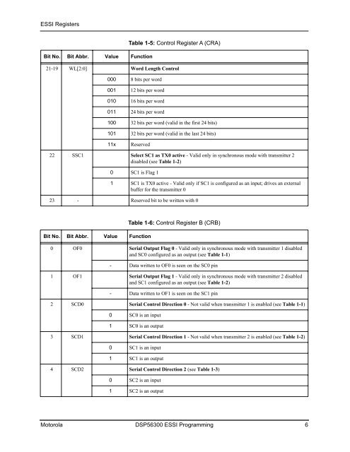
<strong>ESSI</strong> Registers<br />
Bit No. Bit Abbr. Value Function<br />
21-19 WL[2:0]<br />
22 SSC1<br />
000<br />
001<br />
010<br />
011<br />
100<br />
101<br />
11x<br />
0<br />
1<br />
Word Length Control<br />
8 bits per word<br />
12 bits per word<br />
16 bits per word<br />
24 bits per word<br />
32 bits per word (valid in the first 24 bits)<br />
32 bits per word (valid in the last 24 bits)<br />
Reserved<br />
Select SC1 as TX0 active - Valid only in synchronous mode with transmitter 2<br />
disabled (see Table 1-2)<br />
SC1 is Flag 1<br />
23 - Reserved bit to be written with 0<br />
Bit No. Bit Abbr. Value Function<br />
0 OF0<br />
1 OF1<br />
2 SCD0<br />
3 SCD1<br />
4 SCD2<br />
-<br />
-<br />
0<br />
1<br />
0<br />
1<br />
0<br />
1<br />
Table 1-5: Control Register A (CRA)<br />
SC1 is TX0 active - Valid only if SC1 is configured as an input; drives an external<br />
buffer for the transmitter 0<br />
Table 1-6: Control Register B (CRB)<br />
Serial Output Flag 0 - Valid only in synchronous mode with transmitter 1 disabled<br />
and SC0 configured as an output (see Table 1-1)<br />
Data written to OF0 is seen on the SC0 pin<br />
Serial Output Flag 1 - Valid only in synchronous mode with transmitter 2 disabled<br />
and SC1 configured as an output (see Table 1-2)<br />
Data written to OF1 is seen on the SC1 pin<br />
Serial Control Direction 0 - Not valid when transmitter 1 is enabled (see Table 1-1)<br />
SC0 is an input<br />
SC0 is an output<br />
Serial Control Direction 1 - Not valid when transmitter 2 is enabled (see Table 1-2)<br />
SC1 is an input<br />
SC1 is an output<br />
Serial Control Direction 2 (see Table 1-3)<br />
SC2 is an input<br />
SC2 is an output<br />
Motorola DSP56300 <strong>ESSI</strong> <strong>Programming</strong> 6


