MTD Products Aktiengesellschaft • Saarbrücken ... - MTD Europe
MTD Products Aktiengesellschaft • Saarbrücken ... - MTD Europe
MTD Products Aktiengesellschaft • Saarbrücken ... - MTD Europe

Create successful ePaper yourself
Turn your PDF publications into a flip-book with our unique Google optimized e-Paper software.
L10<br />
FORM NO. 769-05342C<br />
<strong>MTD</strong> <strong>Products</strong> <strong>Aktiengesellschaft</strong> <strong>•</strong> <strong>Saarbrücken</strong> <strong>•</strong> Germany
1<br />
D1<br />
A1<br />
A1<br />
B1<br />
A<br />
2x C2<br />
G1<br />
E1<br />
C1<br />
B<br />
2x G<br />
A1<br />
L<br />
A1<br />
E1<br />
C1<br />
F1<br />
C<br />
A2 B2<br />
4x D2 E2<br />
4x F2<br />
G2<br />
O P<br />
D1<br />
B1<br />
J<br />
H1<br />
H1<br />
E<br />
H1<br />
H1<br />
L1<br />
D<br />
H<br />
J2<br />
H2<br />
I2<br />
2x K2<br />
L2<br />
M2<br />
J1<br />
M<br />
K1<br />
Q<br />
I1<br />
I1<br />
F<br />
I<br />
K<br />
N2<br />
I1<br />
I1
1.<br />
2.<br />
5a 6 7<br />
8 9<br />
4<br />
13<br />
10<br />
12<br />
11<br />
14 15 16<br />
5b<br />
J1<br />
H1<br />
H1<br />
L1<br />
K1<br />
X<br />
I1<br />
I1<br />
D2<br />
D2<br />
F2<br />
F2<br />
F2<br />
F2<br />
D2<br />
D2<br />
G2<br />
E2<br />
I<br />
J<br />
B2<br />
C2<br />
A2<br />
C2<br />
1<br />
2<br />
1<br />
C<br />
C<br />
F<br />
E<br />
D<br />
K<br />
3<br />
2<br />
F1<br />
G1<br />
D1<br />
E1<br />
D1<br />
E1 A1<br />
A1<br />
A1<br />
A1<br />
B1<br />
B1<br />
C1<br />
C1<br />
B1<br />
B1<br />
C1<br />
C1
17 18<br />
19<br />
20 21<br />
23 24<br />
26<br />
2<br />
I2<br />
J2<br />
H<br />
1<br />
B<br />
N2<br />
H2<br />
2.<br />
1.<br />
L2<br />
M2<br />
22<br />
25<br />
1<br />
K2<br />
2.<br />
1.<br />
A<br />
2<br />
1.<br />
2.<br />
K2<br />
G
4<br />
6<br />
8
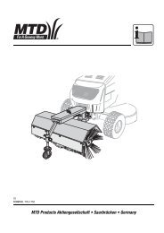
EN Installing the grass catcher<br />
Follow the safety instructions and operating instructions in the operating manual for the lawn tractor.<br />
Before installing the grass catcher, park the lawn tractor on a level surface, apply the parking brake, switch the<br />
engine off and remove the spark-plug terminal.<br />
Check your model number so that you know which installation steps to perform.<br />
Identification of the model number:<br />
You can find the rating plate under the driver’s seat. The fifth to seventh digits of the model number indicate the series.<br />
Example: Model number: 13AN773G600 = Series 700<br />
Installation diagrams<br />
The installation diagrams 1 to 26 are at the front (illustrated fold-out pages) of the manual.<br />
Installing the holder “L” – Only required on units belonging to Series 700<br />
Figs. 1-3<br />
1. Fit a shoulder bolt (D1) and nut (E1) to each of the holders (F1) and (G1) – Fig. 2.<br />
2. Now attach the pre-assembled holders (F1 and G1) to the tractor using the 4 screws (A1) (Fig. 3).<br />
3. Insert the bolts (B1) into the two holders and secure each bolt with a cotter pin (C1) – Fig. 2 and 3.<br />
Installing the mounting frame<br />
Figs. 1 and 4-7<br />
1. Fit the two plates (L1 and K1) to the plate (J1) using 4 screws (H1) and 4 nuts (I1) – Fig. 4.<br />
Note: Ensure that the plates are fitted correctly.<br />
2. Now turn the pre-assembled mounting frame by 180° – see Fig. 5.<br />
3. Fit the holder (C) to the pre-assembled mounting frame using 4 screws (D2) and 4 nuts (F2).<br />
Note: Ensure that correct mounting holes are used in the side retaining plates and initially tighten the nuts only handtight,<br />
as this will facilitate the subsequent installation.<br />
Fig. 5a – for mounting on tractors belonging to the 700 Series.<br />
Fig. 5b – for mounting on all other tractors.<br />
4. Now hook the pre-assembled mounting frame into the shoulder screws on the tractor frame/holder (Fig. 6).<br />
Note: In the tractor series 700 first remove the retaining bolts (B1) and cotter pins (C1) from the holder (Fig. 3).<br />
Then re-attach them after hooking in the mounting frame to secure the mounting frame to the holder as well.<br />
Use mounting holes (X – Fig. 4) for installation.<br />
5. Align the lower hole in the mounting frame with the hole in the hitching device on the tractor chassis. Insert the bolt (E2)<br />
through the mounting holes and secure the bolt with the cotter pin (G2) – Fig. 7.<br />
6. Now tighten all bolts and nuts on the mounting frame.<br />
Installing the grass catcher<br />
Figs. 1, 8-26<br />
1. Push the support plate (I) into the recess on the grass catcher bag carrier (J) and secure the support plate on the grass<br />
catcher carrier using a bolt (B2) and nut (C2) (Figs. 8 and 9).<br />
2. Now hook the pre-assembled part into the mounting frame on the tractor between the 2 lugs and secure the part on the<br />
mounting frame using a bolt (A2) and nut (C2) (Figs. 10 and 11).<br />
3. Install the tube holder (F) by clicking it onto the tubular frame of the grass catcher bag carrier (Fig. 12).<br />
Note: In Step 1 ensure that the edge of the tube holder is flush with the red line on the tubular frame.<br />
4. Install the cover (E) in the hood (D):<br />
1. Push the long end of the cover all the way into the recess of the hood (Fig. 13).<br />
Note: Ensure that the cover is situated under the guide (1) (Fig. 14).<br />
2. Now press the other end of the cover into the designated recess (2) in the hood (Fig. 14).<br />
5. Now position the hood on the mounting eyelets of the tubular frame (Fig. 15).<br />
6. Attach the hood with the bolt (K). To do this, push the bolt (K) through the first mounting eyelet and then continue<br />
through the second mounting eyelet until the end of the bolt touches the hood (Fig. 17). The bolt is now secured on the<br />
hood by the two lugs (Fig. 17).<br />
Note: To facilitate installation, use the inspection opening (1) in the hood (Fig. 16).<br />
7. Open the hood (Fig. 18).<br />
8. To do this, press your right hand onto the rear, right plate (Step 1) and grip the middle plate with your left hand to open<br />
the hood upwards (Step 2) – Fig. 18.<br />
9. Hook both grass catcher bags (G) into the tube holder, ensuring that the more impervious side (closer meshed fabric) is<br />
at the front (Fig. 19).<br />
Note: First hook in the front side and then lower the rear side until the grass catcher bag is situated firmly in the tubular<br />
frame.<br />
4
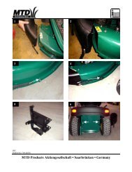
10. Fit the rubber mount (N2) to the mower deck connector (B) using the bolt (H2), washer (I2) and safety cotter pin (J2) –<br />
Fig. 20.<br />
11. Fit the retaining bolt (L2) and nut (M2) to the mower deck (Fig. 21).<br />
12. Installing the mowed deck connector: (Figs. 22 – 24):<br />
1. Open the impact guard on the mower deck and hold it firmly in this position (Fig. 22).<br />
2. Place the rear upper edge of the mower deck connector over the rear upper edge of the mower deck opening.<br />
Now swivel the connector down over the mower deck opening (Fig. 22).<br />
Note: The connector is correctly installed when the lower edge is situated over the lower edge of the mower deck<br />
opening (Fig. 23). Ensure that the installation is correct.<br />
13. Hook the rubber mount into the retaining bolt on the mower deck to secure the mower deck connector on the mower<br />
deck (Fig. 24).<br />
14. Align the guide grooves (1) on the intermediate piece (A) with the mounting lugs (2) on the mower deck connector and<br />
push the intermediate piece all the way onto the mower deck connector (Fig. 25).<br />
15. Secure the intermediate piece on the mower deck connector using the retaining clips (K2) (Fig. 25).<br />
16. Open the hood and push the pipe end section (H) onto the intermediate piece and align it until the lower retaining<br />
groove (1) is situated firmly in the tube holder (2) (Fig. 26).<br />
Note: Ensure that the installation is secure and correct.<br />
17. Close the hood on the grass catcher.<br />
18. Inspect the installation and perform a function test.<br />
Operating the grass catcher:<br />
Emptying<br />
Switch off the unit.<br />
Apply parking brake.<br />
Open grass catcher hood and lift up.<br />
Take hold of the grass catcher baskets by the grip points at the bottom of the grass catcher bags and then take out of<br />
the holders.<br />
Empty grass catcher bags.<br />
Hook in grass catcher bags and close the grass catcher hood again.<br />
Additional information: To ensure that the grass catcher functions optimally, the “Highlift blades” (optional<br />
accessories / or included in product package depending on model) should be installed (tightening torque of the blade screw<br />
122 Nm). Only allow installation of the "Hightlift blades" to be carried out from specialist garage. If required, contact your local<br />
dealer.<br />
5