MDL® Surgical & Prosthetic Technique Manual - Intra-Lock
MDL® Surgical & Prosthetic Technique Manual - Intra-Lock
MDL® Surgical & Prosthetic Technique Manual - Intra-Lock

You also want an ePaper? Increase the reach of your titles
YUMPU automatically turns print PDFs into web optimized ePapers that Google loves.
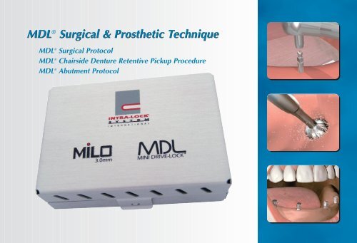
MDL <strong>Surgical</strong> & <strong>Prosthetic</strong> <strong>Technique</strong><br />
® <strong>Surgical</strong> & <strong>Prosthetic</strong> <strong>Technique</strong><br />
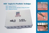
MDL ® <strong>Surgical</strong> Protocol<br />
MDL ® Chairside Denture Retentive Pickup Procedure<br />
MDL ® Abutment Protocol
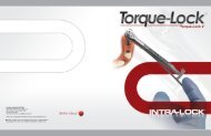
(Fig. 1) The MDL ® 1.2mm Pilot<br />
Drill breaches the gingival tissue.<br />
(Fig. 4) Using Drive-<strong>Lock</strong> <br />
Technology, an MDL ® Implant is<br />
removed from its sterile container.<br />
(Fig. 7) An MDL ® Ratchet Driver<br />
with a Ratchet Wrench is used.<br />
(Fig. 2) Copious sterile saline<br />
irrigation is recommended.<br />
(Fig. 5) MDL ® ’s sharp apical guiding<br />
point initiates self-tapping action.<br />
(Fig. 8) Small incremental turns takes<br />
advantage of bone’s viscoelastic nature.<br />
- 2 -<br />
(Fig. 3) Care is taken to breach<br />
the cortical plate.<br />
(Fig. 6) … threading and expanding<br />
the bone at the same time.<br />
(Fig. 9) Seating is accomplished<br />
when the Ratchet Driver is flush<br />
with the surrounding gingival tissue.
MDL ® <strong>Surgical</strong> Procedure<br />
Overdenture Stabilization<br />
The Mini Drive-<strong>Lock</strong> <strong>Surgical</strong> Kit organizes all instrumentation necessary for the procedure and features a<br />
convenient stainless-steel tray that is easily removed and placed in the sterile operator field.<br />
Light, repeated, intermediate, vertical introduction of the MDL ® 1.2mm Pilot Twist Drill breaches the gingival<br />
tissue and periosteum (Fig. 1). Copious sterile saline irrigation is recommended (Fig. 2). Drilling depth is<br />
approximately one third the length of the implant with care taken to breach the cortical plate (Fig. 3).<br />
MDL ® ’s are packaged suspended on titanium rings specially engineered to facilitate a no-touch delivery and<br />
placement utilizing Drive-<strong>Lock</strong> technology (Fig. 4). The MDL ® Contra-Angle Driver (MDLCAD) is engineered<br />
to slip over the O-ball assembly, firmly engaging the implant for direct delivery and initial seating.<br />
Use a slow speed high-torque handpiece (15 RPM or less) and the MDL ® Contra-Angle Driver to begin to<br />
insert the MDL ® Implant (Fig. 5). MDL ® ’s sharp apical guiding point initiates self-tapping action; threading and<br />
expanding the bone at the same time (Fig. 6). The use of an electric motor with a torque-limiting feature set<br />
to 35Ncm is recommended. The Torque-<strong>Lock</strong> ® Torque Wrench can also be used to determine the implant’s<br />
torque resistance.<br />
When the torque limiter stalls the handpiece or the Torque-<strong>Lock</strong> ® registers<br />
approximately 35Ncm, an MDL ® Ratchet Driver (MDLRD) with a <strong>Surgical</strong><br />
Ratchet Wrench (SRA) is used (Fig. 7). Small incremental turns; with a pause<br />
between each turn takes advantage of bone’s viscoelastic nature (Fig. 8).<br />
MDL ® Implant seating is accomplished when the Ratchet Driver is<br />
flush with the surrounding gingival tissue (Fig. 9).<br />
• • • • • • • • • • • • • • • • • • • • • • • • • • • • • • • • • • • • • • • • • • •<br />
- 3 -
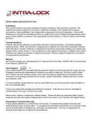
(Fig. 1) A soft lead pencil marks the<br />
heads of the O-Balls.<br />
(Fig. 2) An impression of the O-Balls is<br />
transferred to the denture.<br />
(Fig. 4) All openings are relieved. (Fig. 5) It is verified that the appliance is<br />
seated passively.<br />
(Fig. 7) All Retentive Housings are snapped<br />
into place.<br />
(Fig. 8) Appliance is seated passively in<br />
maximum intercuspation.<br />
- 4 -<br />
(Fig. 3) A resin bur relieves the opening.<br />
(Fig. 6) A Retentive Housing is snapped<br />
over the O-Ball.<br />
(Fig. 9) Holes are punched in a rubber dam<br />
at each implant site.
MDL ® Chairside Denture Retentive Pickup Procedure<br />
Overdenture Stabilization<br />
For chairside pickup of the MDL ® denture retentive component transfer the position of the O-Balls to the<br />
tissue-bearing surface of the denture by marking the heads of the O-Balls with a soft lead pencil (Fig. 1)<br />
or capturing their impression by inserting a strip of soft silicone or soft wax inside the denture. An impression<br />
is clearly visible on the tissue-bearing surface of the denture (Fig. 2).<br />
Using a resin bur, relieve the opening around the abutment impressions or markings in the denture<br />
(Fig. 3 & 4).<br />
Try the denture in the patient’s mouth and verify that the appliance is seated passively while in maximum<br />
intercuspation. The O-Balls should not touch any part of the denture. Have the patient close into maximum<br />
intercuspation and observe that the denture is stable and properly equilibrated at this point (Fig. 5).<br />
Snap a Retentive Housing Assembly over each O-Ball (Fig. 6 & 7). Try the denture in the patient’s mouth<br />
again and check to ensure that the appliance is seated passively while in maximum intercuspation (Fig. 8).<br />
Remove the Retentive Housings. Punch holes in a rubber dam at each implant site (Fig. 9).<br />
• • • • • • • • • • • • • • • • • • • • • • • • • • • • • • • • • • • • • • • • • • • • • • • • • • • •<br />
- 5 -
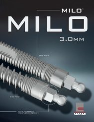
(Fig. 10) The rubber dam is placed over<br />
each abutment.<br />
(Fig. 13) The abutment recesses are filled<br />
with self cure resin.<br />
(Fig. 16) The patient closes into maximum<br />
intercuspation.<br />
(Fig. 11) The O-Ball heads are left exposed<br />
and lubricated.<br />
(Fig. 14) This material is painted over each<br />
housing.<br />
(Fig. 17) The denture and the rubber dam is<br />
removed.<br />
- 6 -<br />
(Fig. 12) A Retentive Housing is snapped<br />
over each O-Ball.<br />
(Fig. 15) The denture is seated when the<br />
acrylic becomes resistant to flow.<br />
(Fig. 18) Flash is trimmed and any minor<br />
voids or discrepancies filled.
MDL ® Chairside Denture Retentive Pickup Procedure (Cont.)<br />
Overdenture Stabilization<br />
Place the rubber dam over each abutment, leaving only the O-Ball heads exposed. Lubricate the O-Ball heads<br />
(Fig. 10 & 11). These steps will prevent any acrylic lock-on.<br />
Snap a Retentive Housing Assembly over each O-Ball in preparation for final seating (Fig. 12).<br />
Clean, wash and dry the denture. Fill the abutment recesses with self cure resin (Fig. 13). Paint a small amount<br />
of this material over each retentive housing (Fig. 14). As soon as the acrylic in the denture becomes resistant to<br />
flow, seat the denture, keeping light, bilateral pressure on the occlusal surface (Fig. 15).<br />
While maintaining light bilateral pressure on the denture, have the patient close gently into maximum<br />
intercuspation (Fig. 16).<br />
Allow the acrylic to fully polymerize. After the acrylic has set, remove the denture and the<br />
rubber dam (Fig. 17). Trim flash and fill any minor voids or discrepancies. Ensure that<br />
there are no sharp edges on the tissue-bearing surface of the denture (Fig. 18).<br />
Recheck the occlusion. Confirm proper occlusal contacts.<br />
• • • • • • • • • • • • • • • • • • • • • • • • • • • • • • • • • • • • • • • • • • •<br />
- 7 -
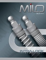
(Fig. 1) MDL ® Implant is surgically<br />
placed in to position.<br />
(Fig. 4) Loaded tray is placed for the<br />
appropriate amount of time.<br />
(Fig. 2) MDL ® Impression Coping (MDLT)<br />
slides over the O-Ball Abutment.<br />
(Fig. 5) Coping is firmly picked up in the<br />
impression.<br />
(Fig. 7) Working model is poured. (Fig. 8) Appropriate MDL ® Abutment is<br />
prepared and cemented over the O-Ball<br />
with resin cement.<br />
- 8-<br />
(Fig. 3) Pre-formed custom tray is loaded<br />
with a monophase impression material.<br />
(Fig. 6) MDL ® Laboratory Analog (MDLA)<br />
is Inserted into the Impression Coping.<br />
(Fig. 9) The prosthesis is cemented into<br />
place after occlusion and esthetics are<br />
confirmed.
MDL ® Cement-Over Abutment Preparation and<br />
Impression <strong>Prosthetic</strong> <strong>Technique</strong><br />
Cement-Over Abutments*, available in Straight, 15 0 Angled, Wide, Plastic Castable, and Orthodontic<br />
configurations, provide the clinician with an unsurpassed range of prosthetic options. Cement-Over <br />
Abutments* can be prepared extra orally and simply fit over the O-Ball Assembly. Once cemented in place<br />
with resin cement, abutment and implant form one unit; resistant and strong as a one-piece. An Analog and<br />
Impression Coping complement the system.<br />
Place an MDL ® Impression Coping (MDLT) over each O-Ball assembly (Fig. 2). It snaps on<br />
and holds itself in place.<br />
Load an impression tray, preferably with a monophase product (Fig. 3).<br />
The loaded tray is placed for the impression material manufacturer's recommended time (Fig. 4).<br />
The copings will be picked up in the impression material (Fig. 5).<br />
Insert MDL ® Laboratory Analogs (MDLA) into the “captured” Impression Copings (MDLT) (Fig. 6).<br />
Pour the working model either in the dental office or laboratory (Fig. 7).<br />
Prepare and index the appropriate MDL ® Cement-On Abutment (Fig. 8).<br />
Upon delivery of the prosthesis, the abutments are cemented over their<br />
respective O-ball abutment assemblies with resin cement (e.g.: Core Paste by Denmat ® ).<br />
Use only resin cement for this step (Fig. 9). The prosthesis is then placed and the fit,<br />
occlusion and esthetics are confirmed by clinical and radiographic examinations. Upon<br />
satisfaction of all parameters, cement the prosthesis into place with temporary cement.<br />
A metal reinforced bridge is recommended for rigidity.<br />
• • • • • • • • • • • • • • • • • • • • • • • • • • • • • • • • • • • • • • • • • • • • • • • • • • • • • •<br />
- 9 -
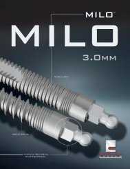
Mini Drive-<strong>Lock</strong> Implants One Implant... Multiple Applications.<br />
Mini Drive-<strong>Lock</strong> (MDL ® ) is <strong>Intra</strong>-<strong>Lock</strong>’s<br />
one-piece small diameter dental implant.<br />
The system is ideal for long-term denture<br />
stabilization or fixed prosthetics. MDL ® is a<br />
true 'convertible' implant with one-piece<br />
solid strength and two-piece versatility.<br />
Patented* Cement-Over Abutments, simply<br />
fit over the O-Ball Assembly and convert the<br />
implant from removable to fixed or orthodontic<br />
treatment options. The system’s unique Drive-<strong>Lock</strong> <br />
instruments reduce delivery and placement to one fluid<br />
motion. Once in place, <strong>Intra</strong>-<strong>Lock</strong>’s extremely<br />
hydrophilic, bio-active OSSEAN ® Surface promotes<br />
rapid early healing and increased biomechanical fixation ** .<br />
- 10 -<br />
• “Long-Term”<br />
Applications<br />
• OSSEAN ® Surface<br />
Applied to Collar<br />
and Body<br />
• Cement-Over <br />
Abutments<br />
• Direct<br />
Delivery
<strong>Prosthetic</strong> Components<br />
Cement-Over 0 Abutments*, available in Straight, 15 Angled, Wide, Plastic Castable, and<br />
Orthodontic configurations, provide the clinician with an unsurpassed range of prosthetic options.<br />
Cement-Over Cement-Over<br />
Abutments* can be prepared extra orally and simply fit over the O-Ball Assembly.<br />
Once cemented in place with resin cement, abutment and implant form one unit; resistant and strong<br />
as a one-piece. An Analog and Impression Coping complement the system.<br />
Abutment System<br />
MDLSA MDLAA15 WCA<br />
MLHC<br />
MDLA<br />
MDLMH<br />
MDLPA MDLOA<br />
MDLOR MDLMOR<br />
MDLT<br />
MDLMMH<br />
Cement-Over Abutments<br />
Cements over O-Ball Assembly for fixed bridges, Straight ....................... MDLSA<br />
Cements over O-Ball Assembly for fixed bridges, Angulated 15° ........<br />
MDLAA15<br />
Cements over O-Ball Assembly for fixed bridges, Wide .............................. WCA<br />
Plastic Castable Abutment for fixed bridges ............................................. MDLPA<br />
Orthodontic Abutment fits over O-Ball Assembly................................... MDLOA<br />
Healing Abutments<br />
Plastic Healing Cap for Press Fit on O-Ball Assembly ............................... MLHC<br />
Mini Drive-<strong>Lock</strong> Metal Housing with O-Ring<br />
O-Ring encapsulated in MICRO Metal Housing ................................. MDLMMH<br />
O-Ring encapsulated in LARGE Metal Housing ..................................... MDLMH<br />
MDL ® O-Ring Replacements<br />
For MICRO Housing (Quantity of 10) ................................................. MDLMOR<br />
For LARGE Housing (Quantity of 10) ..................................................... MDLOR<br />
Mini Drive-<strong>Lock</strong> Impression Coping<br />
Pick up Impression Coping ......................................................................... MDLT<br />
Mini Drive-<strong>Lock</strong> Laboratory Analog<br />
Replicates the MDL ® Implant and Abutment ............................................. MDLA<br />
- 11 -
GLOBAL HEADQUARTERS<br />
6560 West Rogers Circle, Bldg. 24 • Boca Raton, Florida 33487 USA<br />
Tel: 877-330-0338<br />
www.intra-lock.com • info@intra-lock.com<br />
Prior to the placement of MDL ® implants, appropriate and adequate training in all phases of MDL ® Implant procedures is strongly recommended.<br />
A comprehensive patient interview, medical/dental history, treatment plan and a complete oral examination should be conducted.<br />
Diagnostic radiographs and mounted study models, if appropriate, should also be obtained.<br />
CE<br />
<strong>Intra</strong>-<strong>Lock</strong> ® , OSSEAN ® , MDL ® Mini Drive-<strong>Lock</strong> are registered trademarks of <strong>Intra</strong>-<strong>Lock</strong> International, Inc.<br />
Drive-<strong>Lock</strong> is a trademark of <strong>Intra</strong>-<strong>Lock</strong> International, Inc.<br />
*U.S. Patent 7,033,174 - U.S. Patent 7,217,130 - U.S. Patent 7,131,840 and other U.S. & Foreign Patents Pending.<br />
**Data on file.<br />
0499 • EC Rep: <strong>Intra</strong>-<strong>Lock</strong> System Europa, Spa., I-84100 Salerno • © Copyright 2008, <strong>Intra</strong>-<strong>Lock</strong> ® System International • S4EN-08-6