3D Processing and Analysis with ImageJ
3D Processing and Analysis with ImageJ
3D Processing and Analysis with ImageJ
You also want an ePaper? Increase the reach of your titles
YUMPU automatically turns print PDFs into web optimized ePapers that Google loves.
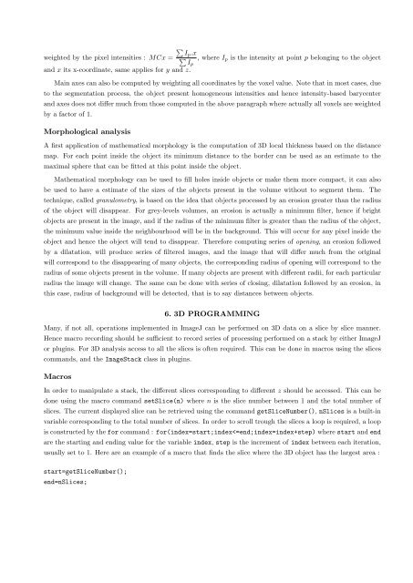
Ip.x<br />
weighted by the pixel intensities : MCx = , where Ip is the intensity at point p belonging to the object<br />
Ip<br />
<strong>and</strong> x its x-coordinate, same applies for y <strong>and</strong> z.<br />
Main axes can also be computed by weighting all coordinates by the voxel value. Note that in most cases, due<br />
to the segmentation process, the object present homogeneous intensities <strong>and</strong> hence intensity-based barycenter<br />
<strong>and</strong> axes does not differ much from those computed in the above paragraph where actually all voxels are weighted<br />
by a factor of 1.<br />
Morphological analysis<br />
A first application of mathematical morphology is the computation of <strong>3D</strong> local thickness based on the distance<br />
map. For each point inside the object its minimum distance to the border can be used as an estimate to the<br />
maximal sphere that can be fitted at this point inside the object.<br />
Mathematical morphology can be used to fill holes inside objects or make them more compact, it can also<br />
be used to have a estimate of the sizes of the objects present in the volume <strong>with</strong>out to segment them. The<br />
technique, called granulometry, is based on the idea that objects processed by an erosion greater than the radius<br />
of the object will disappear. For grey-levels volumes, an erosion is actually a minimum filter, hence if bright<br />
objects are present in the image, <strong>and</strong> if the radius of the minimum filter is greater than the radius of the object,<br />
the minimum value inside the neighbourhood will be in the background. This will occur for any pixel inside the<br />
object <strong>and</strong> hence the object will tend to disappear. Therefore computing series of opening, an erosion followed<br />
by a dilatation, will produce series of filtered images, <strong>and</strong> the image that will differ much from the original<br />
will correspond to the disappearing of many objects, the corresponding radius of opening will correspond to the<br />
radius of some objects present in the volume. If many objects are present <strong>with</strong> different radii, for each particular<br />
radius the image will change. The same can be done <strong>with</strong> series of closing, dilatation followed by an erosion, in<br />
this case, radius of background will be detected, that is to say distances between objects.<br />
6. <strong>3D</strong> PROGRAMMING<br />
Many, if not all, operations implemented in <strong>ImageJ</strong> can be performed on <strong>3D</strong> data on a slice by slice manner.<br />
Hence macro recording should be sufficient to record series of processing performed on a stack by either <strong>ImageJ</strong><br />
or plugins. For <strong>3D</strong> analysis access to all the slices is often required. This can be done in macros using the slices<br />
comm<strong>and</strong>s, <strong>and</strong> the ImageStack class in plugins.<br />
Macros<br />
In order to manipulate a stack, the different slices corresponding to different z should be accessed. This can be<br />
done using the macro comm<strong>and</strong> setSlice(n) where n is the slice number between 1 <strong>and</strong> the total number of<br />
slices. The current displayed slice can be retrieved using the comm<strong>and</strong> getSliceNumber(), nSlices is a built-in<br />
variable corresponding to the total number of slices. In order to scroll trough the slices a loop is required, a loop<br />
is constructed by the for comm<strong>and</strong> : for(index=start;index


