Minimize Winding Losses in - Power Electronics
Minimize Winding Losses in - Power Electronics
Minimize Winding Losses in - Power Electronics

Create successful ePaper yourself
Turn your PDF publications into a flip-book with our unique Google optimized e-Paper software.
erties of the core material, which exhibits power losses <strong>in</strong> the<br />
form of hysteresis and eddy currents with<strong>in</strong> the core itself.<br />
<strong>W<strong>in</strong>d<strong>in</strong>g</strong> losses come from the resistance <strong>in</strong> the w<strong>in</strong>d<strong>in</strong>g,<br />
typically copper.<br />
Inductors used for switch-mode power applications are<br />
subject to high-frequency current ripple, which can make<br />
the effective w<strong>in</strong>d<strong>in</strong>g resistance and the associated copper<br />
losses very high. The w<strong>in</strong>d<strong>in</strong>g resistance of power <strong>in</strong>ductors<br />
<strong>in</strong>cludes both the dc resistance and an<br />
ac component of resistance that is<br />
a result of both sk<strong>in</strong> effects and<br />
proximity effects.<br />
A time-dependent current<br />
<strong>in</strong>duces a flux, which <strong>in</strong> turn<br />
<strong>in</strong>duces small currents<br />
with<strong>in</strong> the wire. S<strong>in</strong>ce<br />
very little current passes<br />
through the center of the<br />
w<strong>in</strong>d<strong>in</strong>g, the effective<br />
cross-sectional area is<br />
reduced and the resistance<br />
is <strong>in</strong>creased. These<br />
losses <strong>in</strong>crease <strong>in</strong> magnitude<br />
as the frequency<br />
and current <strong>in</strong>crease.<br />
At switch-mode frequencies,<br />
the ac component<br />
of resistance can be<br />
very high, often greatly<br />
exceed<strong>in</strong>g dc resistance<br />
and result<strong>in</strong>g <strong>in</strong> high<br />
copper losses. With<br />
gapped-power <strong>in</strong>ductors,<br />
the field near the<br />
gap produces a strong<br />
local proximity effect<br />
and can produce very<br />
high ac copper resistance<br />
and losses, even lead<strong>in</strong>g to the<br />
failure of the <strong>in</strong>ductor.<br />
<strong>Power</strong> loss <strong>in</strong> any magnetic device<br />
is the sum of these effects, and the design<br />
process is made more difficult by their relationship<br />
to one another. For <strong>in</strong>stance, common methods of reduc<strong>in</strong>g<br />
ac resistance, such as the use of Litz wire, greatly reduce<br />
the cross-sectional area of the conductor and drastically<br />
<strong>in</strong>crease dc resistance. Foil <strong>in</strong>ductors are often used to<br />
m<strong>in</strong>imize w<strong>in</strong>d<strong>in</strong>g losses <strong>in</strong> an application of high dc current,<br />
because of their efficient use of the w<strong>in</strong>d<strong>in</strong>g w<strong>in</strong>dow.<br />
However, even a small amount of ac current can cause<br />
significant losses <strong>in</strong> these coils.<br />
Such sacrifices are unacceptable <strong>in</strong> many of today’s<br />
applications. Many dc-dc converters require an <strong>in</strong>ductor<br />
that can carry a large dc current with an ac ripple. Even<br />
when the ac component is small <strong>in</strong> comparison to the<br />
dc current, the ac resistance can be orders of magnitude<br />
larger than the dc resistance. The problem is more acute<br />
as current level and frequency of operation <strong>in</strong>crease <strong>in</strong><br />
modern designs.<br />
Fortunately, there are solutions to the problem of ac<br />
copper losses. Keep<strong>in</strong>g the w<strong>in</strong>d<strong>in</strong>gs to a s<strong>in</strong>gle layer substantially<br />
mitigates ac copper losses. Us<strong>in</strong>g a powdered core<br />
with no gap will substantially reduce proximity effects and<br />
the result<strong>in</strong>g ac copper losses.<br />
However, powdered cores typically have significantly<br />
higher core losses than ferrite cores, and for high-ripple<br />
applications, a gapped core is sometimes preferred due<br />
to lower core losses. Or, it may also be desirable to use a<br />
relatively high-permeability powdered core with a gap, to<br />
take advantage of the higher B SAT available with this type of<br />
core material. In these cases, the gap-fr<strong>in</strong>g<strong>in</strong>g field must be<br />
dealt with or copper losses can be very high.<br />
Shaped-Foil Technology<br />
Foil w<strong>in</strong>d<strong>in</strong>gs are a compell<strong>in</strong>g alternative because of<br />
the comparatively high w<strong>in</strong>dow utilization and very low<br />
result<strong>in</strong>g dc resistance. West Coast Magnetics has worked<br />
with the Thayer School of Eng<strong>in</strong>eer<strong>in</strong>g at Dartmouth to<br />
develop a shaped-foil technology [1] that has both low dc<br />
and low ac copper losses. The new technology shapes the<br />
foil <strong>in</strong> the vic<strong>in</strong>ity of the gap to use the gap-fr<strong>in</strong>g<strong>in</strong>g flux to<br />
equalize the current distribution throughout the foil and<br />
m<strong>in</strong>imize the sk<strong>in</strong> and proximity effects.<br />
An <strong>in</strong>ductor employ<strong>in</strong>g this technology comb<strong>in</strong>es the<br />
very low dc resistance of a copper-foil w<strong>in</strong>d<strong>in</strong>g with the<br />
low ac resistance of a Litz-wire w<strong>in</strong>d<strong>in</strong>g. In particular,<br />
for high-current, high-ripple <strong>in</strong>ductors, the shaped-foil<br />
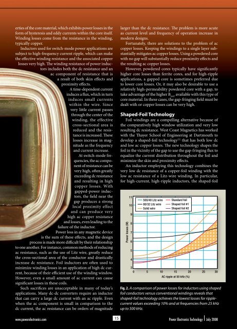
Fig. 2. A comparison of power losses for <strong>in</strong>ductors us<strong>in</strong>g shaped<br />
foil conductors versus conventional w<strong>in</strong>d<strong>in</strong>gs reveals that<br />
shaped-foil technology achieves the lowest losses for ripple-<br />
current values exceed<strong>in</strong>g 10% and at frequencies from 25 kHz<br />
up to 500 kHz.<br />
0708PETWCoast_F2<br />
www.powerelectronics.com 15<br />
<strong>Power</strong> <strong>Electronics</strong> Technology July 2008<br />
10<br />
9<br />
8<br />
7<br />
6<br />
<strong>Power</strong> losses (W) 11<br />
5<br />
4<br />
500/40 Litz wire<br />
80/32 Litz wire<br />
Solid wire<br />
Standard foil<br />
Shaped foil #1<br />
Shaped foil #2<br />
3<br />
0 5 10 15 20 25 30<br />
AC ripple at 50 kHz (%)