Minimize Winding Losses in - Power Electronics
Minimize Winding Losses in - Power Electronics
Minimize Winding Losses in - Power Electronics

Create successful ePaper yourself
Turn your PDF publications into a flip-book with our unique Google optimized e-Paper software.
<strong>M<strong>in</strong>imize</strong> <strong>W<strong>in</strong>d<strong>in</strong>g</strong> <strong>Losses</strong> <strong>in</strong><br />
High-Frequency<br />
Weyman<br />
InductorsBy<br />
Lundquist,<br />
President and Eng<strong>in</strong>eer<strong>in</strong>g<br />
Manager, West Coast<br />
Magnetics, Stockton,Calif.<br />
A foil-w<strong>in</strong>d<strong>in</strong>g technology, which reduces losses of <strong>in</strong>ductors<br />
at high ripple currents and high power levels, and a freeware<br />
program, which optimizes designs us<strong>in</strong>g Litz wire, offer designers<br />
new tools for reduc<strong>in</strong>g w<strong>in</strong>d<strong>in</strong>g losses at high frequencies.<br />
<strong>Power</strong> electronics are rapidly expand<strong>in</strong>g <strong>in</strong>to new applications as highpower<br />
semiconductor devices <strong>in</strong>crease their rated operat<strong>in</strong>g current and<br />
frequencies to higher and higher levels. As a basic build<strong>in</strong>g block of virtually<br />
all power electronics equipment, <strong>in</strong>ductors have a unique potential<br />
for improvement. That’s because <strong>in</strong>ductors are usually the largest, most<br />
expensive and volumetrically <strong>in</strong>efficient items <strong>in</strong> a power system.<br />
Consequently, improvements <strong>in</strong> <strong>in</strong>ductor design can have a great impact on the size<br />
and cost of the <strong>in</strong>ductor, which can have a significant impact on the rest of the power<br />
electronics design. One way to help shr<strong>in</strong>k a power <strong>in</strong>ductor is to reduce its losses at<br />
high frequencies, so that a lower value of <strong>in</strong>ductance may be specified and, therefore, a<br />
smaller <strong>in</strong>ductor may be used <strong>in</strong> the system.<br />
To lower an <strong>in</strong>ductor’s power losses at high frequencies, designers must understand<br />
the role of w<strong>in</strong>d<strong>in</strong>g losses and the options available for reduc<strong>in</strong>g those losses. Those options<br />
<strong>in</strong>clude a new foil-w<strong>in</strong>d<strong>in</strong>g technique that achieves low losses for <strong>in</strong>ductors operat<strong>in</strong>g<br />
at high ripple current and high power levels. For designers look<strong>in</strong>g to optimize <strong>in</strong>ductor<br />
designs us<strong>in</strong>g Litz wire, there’s also a new tool to aid the design process. This tool takes the<br />
form of a freeware program that<br />
allows the user to optimize the<br />
strand<strong>in</strong>g and position<strong>in</strong>g of the<br />
w<strong>in</strong>d<strong>in</strong>g <strong>in</strong>side of the available<br />
w<strong>in</strong>d<strong>in</strong>g w<strong>in</strong>dow.<br />
Understand<strong>in</strong>g<br />
<strong>W<strong>in</strong>d<strong>in</strong>g</strong> <strong>Losses</strong><br />
There are two pr<strong>in</strong>ciple mechanisms<br />
for loss <strong>in</strong> <strong>in</strong>ductors, core<br />
losses and w<strong>in</strong>d<strong>in</strong>g losses. Core<br />
losses <strong>in</strong>volve the magnetic prop-<br />
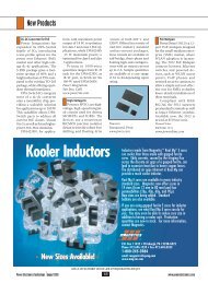
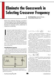
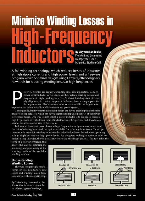
Fig. 1. A w<strong>in</strong>d<strong>in</strong>g cross section of a<br />
90-µH, 40-A <strong>in</strong>ductor is shown for<br />
six different types of w<strong>in</strong>d<strong>in</strong>gs.<br />
Standard foil Shaped foil #1 Shaped foil #2<br />
20/32 Litz wire Solid wire 50/40 Litz<br />
wire<br />
80/32 Litz wire Solid wire 500/40 Litz wire<br />
<strong>Power</strong> <strong>Electronics</strong> Technology July 2008 14<br />
www.powerelectronics.com
erties of the core material, which exhibits power losses <strong>in</strong> the<br />
form of hysteresis and eddy currents with<strong>in</strong> the core itself.<br />
<strong>W<strong>in</strong>d<strong>in</strong>g</strong> losses come from the resistance <strong>in</strong> the w<strong>in</strong>d<strong>in</strong>g,<br />
typically copper.<br />
Inductors used for switch-mode power applications are<br />
subject to high-frequency current ripple, which can make<br />
the effective w<strong>in</strong>d<strong>in</strong>g resistance and the associated copper<br />
losses very high. The w<strong>in</strong>d<strong>in</strong>g resistance of power <strong>in</strong>ductors<br />
<strong>in</strong>cludes both the dc resistance and an<br />
ac component of resistance that is<br />
a result of both sk<strong>in</strong> effects and<br />
proximity effects.<br />
A time-dependent current<br />
<strong>in</strong>duces a flux, which <strong>in</strong> turn<br />
<strong>in</strong>duces small currents<br />
with<strong>in</strong> the wire. S<strong>in</strong>ce<br />
very little current passes<br />
through the center of the<br />
w<strong>in</strong>d<strong>in</strong>g, the effective<br />
cross-sectional area is<br />
reduced and the resistance<br />
is <strong>in</strong>creased. These<br />
losses <strong>in</strong>crease <strong>in</strong> magnitude<br />
as the frequency<br />
and current <strong>in</strong>crease.<br />
At switch-mode frequencies,<br />
the ac component<br />
of resistance can be<br />
very high, often greatly<br />
exceed<strong>in</strong>g dc resistance<br />
and result<strong>in</strong>g <strong>in</strong> high<br />
copper losses. With<br />
gapped-power <strong>in</strong>ductors,<br />
the field near the<br />
gap produces a strong<br />
local proximity effect<br />
and can produce very<br />
high ac copper resistance<br />
and losses, even lead<strong>in</strong>g to the<br />
failure of the <strong>in</strong>ductor.<br />
<strong>Power</strong> loss <strong>in</strong> any magnetic device<br />
is the sum of these effects, and the design<br />
process is made more difficult by their relationship<br />
to one another. For <strong>in</strong>stance, common methods of reduc<strong>in</strong>g<br />
ac resistance, such as the use of Litz wire, greatly reduce<br />
the cross-sectional area of the conductor and drastically<br />
<strong>in</strong>crease dc resistance. Foil <strong>in</strong>ductors are often used to<br />
m<strong>in</strong>imize w<strong>in</strong>d<strong>in</strong>g losses <strong>in</strong> an application of high dc current,<br />
because of their efficient use of the w<strong>in</strong>d<strong>in</strong>g w<strong>in</strong>dow.<br />
However, even a small amount of ac current can cause<br />
significant losses <strong>in</strong> these coils.<br />
Such sacrifices are unacceptable <strong>in</strong> many of today’s<br />
applications. Many dc-dc converters require an <strong>in</strong>ductor<br />
that can carry a large dc current with an ac ripple. Even<br />
when the ac component is small <strong>in</strong> comparison to the<br />
dc current, the ac resistance can be orders of magnitude<br />
larger than the dc resistance. The problem is more acute<br />
as current level and frequency of operation <strong>in</strong>crease <strong>in</strong><br />
modern designs.<br />
Fortunately, there are solutions to the problem of ac<br />
copper losses. Keep<strong>in</strong>g the w<strong>in</strong>d<strong>in</strong>gs to a s<strong>in</strong>gle layer substantially<br />
mitigates ac copper losses. Us<strong>in</strong>g a powdered core<br />
with no gap will substantially reduce proximity effects and<br />
the result<strong>in</strong>g ac copper losses.<br />
However, powdered cores typically have significantly<br />
higher core losses than ferrite cores, and for high-ripple<br />
applications, a gapped core is sometimes preferred due<br />
to lower core losses. Or, it may also be desirable to use a<br />
relatively high-permeability powdered core with a gap, to<br />
take advantage of the higher B SAT available with this type of<br />
core material. In these cases, the gap-fr<strong>in</strong>g<strong>in</strong>g field must be<br />
dealt with or copper losses can be very high.<br />
Shaped-Foil Technology<br />
Foil w<strong>in</strong>d<strong>in</strong>gs are a compell<strong>in</strong>g alternative because of<br />
the comparatively high w<strong>in</strong>dow utilization and very low<br />
result<strong>in</strong>g dc resistance. West Coast Magnetics has worked<br />
with the Thayer School of Eng<strong>in</strong>eer<strong>in</strong>g at Dartmouth to<br />
develop a shaped-foil technology [1] that has both low dc<br />
and low ac copper losses. The new technology shapes the<br />
foil <strong>in</strong> the vic<strong>in</strong>ity of the gap to use the gap-fr<strong>in</strong>g<strong>in</strong>g flux to<br />
equalize the current distribution throughout the foil and<br />
m<strong>in</strong>imize the sk<strong>in</strong> and proximity effects.<br />
An <strong>in</strong>ductor employ<strong>in</strong>g this technology comb<strong>in</strong>es the<br />
very low dc resistance of a copper-foil w<strong>in</strong>d<strong>in</strong>g with the<br />
low ac resistance of a Litz-wire w<strong>in</strong>d<strong>in</strong>g. In particular,<br />
for high-current, high-ripple <strong>in</strong>ductors, the shaped-foil<br />
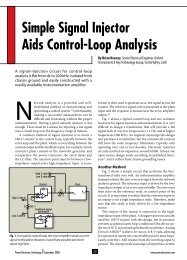
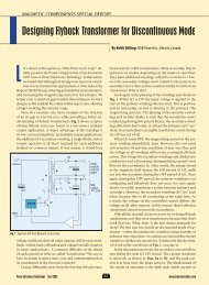
Fig. 2. A comparison of power losses for <strong>in</strong>ductors us<strong>in</strong>g shaped<br />
foil conductors versus conventional w<strong>in</strong>d<strong>in</strong>gs reveals that<br />
shaped-foil technology achieves the lowest losses for ripple-<br />
current values exceed<strong>in</strong>g 10% and at frequencies from 25 kHz<br />
up to 500 kHz.<br />
0708PETWCoast_F2<br />
www.powerelectronics.com 15<br />
<strong>Power</strong> <strong>Electronics</strong> Technology July 2008<br />
10<br />
9<br />
8<br />
7<br />
6<br />
<strong>Power</strong> losses (W) 11<br />
5<br />
4<br />
500/40 Litz wire<br />
80/32 Litz wire<br />
Solid wire<br />
Standard foil<br />
Shaped foil #1<br />
Shaped foil #2<br />
3<br />
0 5 10 15 20 25 30<br />
AC ripple at 50 kHz (%)
INNOVATIVE<br />
MAGNETICS<br />
TO POWER<br />
YOUR PRODUCTS<br />
BETTER PERFORMANCE.<br />
BETTER PRICE.<br />
GUARANTEED.<br />
* *<br />
If we can’t<br />
improve your<br />
<strong>Power</strong> Magnetics,<br />
we’ll give you a<br />
$25 STARBUCKS<br />
GIFT CARD just<br />
for lett<strong>in</strong>g us try.<br />
sales@magicall.biz<br />
www.magicall.biz<br />
(805) 484-4300<br />
w<strong>in</strong>d<strong>in</strong>g <strong>Losses</strong><br />
w<strong>in</strong>d<strong>in</strong>g technology can be the lowestloss<br />
solution.<br />
An experiment was conducted<br />
to compare the new foil technology<br />
to conventional w<strong>in</strong>d<strong>in</strong>gs <strong>in</strong>clud<strong>in</strong>g<br />
solid-wire, Litz-wire and full unmodified-foil<br />
w<strong>in</strong>d<strong>in</strong>gs. [2] For this<br />
experiment, a series of 90-µH, 40-A<br />
<strong>in</strong>ductors were built and tested us<strong>in</strong>g<br />
best practices. Each of the prototype<br />
<strong>in</strong>ductors was constructed us<strong>in</strong>g the<br />
same E70/33/32 ferrite core of material<br />
EPCOS N67, which had a 2.63-mm<br />
gap <strong>in</strong> the center leg (designated<br />
B66371-G-X167). Fifteen turns were<br />
wound on all the <strong>in</strong>ductors, produc<strong>in</strong>g<br />
an <strong>in</strong>ductance of 90 µH to 95 µH.<br />
The w<strong>in</strong>d<strong>in</strong>gs are shown <strong>in</strong> Fig. 1.<br />
In each case, best w<strong>in</strong>d<strong>in</strong>g practices<br />
were employed, which <strong>in</strong>cluded s<strong>in</strong>glelayer<br />
w<strong>in</strong>d<strong>in</strong>gs for the Litz and solidwire<br />
samples, and <strong>in</strong> every case, the<br />
conductor area was maximized <strong>in</strong> the<br />
w<strong>in</strong>d<strong>in</strong>g w<strong>in</strong>dow.<br />
The solid-wire sample consisted<br />
of four layers of 10-gauge wire, 15<br />
turns per layer, with the w<strong>in</strong>d<strong>in</strong>gs<br />
connected <strong>in</strong> parallel. Two Litz-wire<br />
samples were constructed, one us<strong>in</strong>g<br />
500 strands of 40 AWG Litz wire and<br />
the other 80 strands of 32 AWG Litz<br />
wire. As with the solid-wire prototype,<br />
these <strong>in</strong>ductors were wound <strong>in</strong> four<br />
parallel layers of 15 turns.<br />
A standard foil <strong>in</strong>ductor was constructed<br />
of 15 turns of 0.020-<strong>in</strong>. copper,<br />
measur<strong>in</strong>g 1.55 <strong>in</strong>. wide and<br />
separated by 0.003 <strong>in</strong>. 3 1.69 <strong>in</strong>. of<br />
Nomex <strong>in</strong>sulator. Two samples were<br />
built us<strong>in</strong>g the new shaped-foil technology.<br />
One sample had a foil shape<br />
optimized for a current of 40 Adc with<br />
a 15% (6-A peak-to-peak) ripple at<br />
50 kHz, and the other sample was optimized<br />
for a ripple of 22.5% at 50 kHz.<br />
The total core and copper losses for<br />
each of these <strong>in</strong>ductors were determ<strong>in</strong>ed<br />
experimentally and the results<br />
are plotted <strong>in</strong> Fig. 2. The hatched area<br />
illustrates the loss reduction that is<br />
observed with the new foil-w<strong>in</strong>d<strong>in</strong>g<br />
technology versus conventionally<br />
wound <strong>in</strong>ductors. Core losses were the<br />
same for all the <strong>in</strong>ductors, so the loss<br />
reduction is observed <strong>in</strong> the w<strong>in</strong>d<strong>in</strong>gs<br />
exclusively.<br />
Wire placement <strong>in</strong> green, gap at (0, bw/2)<br />
Experimental data was collected<br />
for these sample <strong>in</strong>ductors at ripple-current<br />
values from 1% to 30%<br />
and frequencies from 10 kHz up to<br />
500 kHz. This data demonstrates that<br />
the shaped-foil technology was the<br />
lowest-loss solution for ripple-current<br />
values exceed<strong>in</strong>g 10% and at frequencies<br />
from 25 kHz up to 500 kHz.<br />
Litz-Wire <strong>W<strong>in</strong>d<strong>in</strong>g</strong>s<br />
Other work done by the Thayer<br />
School of Eng<strong>in</strong>eer<strong>in</strong>g and West Coast<br />
Magnetics has led to advances <strong>in</strong> the<br />
use of Litz wire for w<strong>in</strong>d<strong>in</strong>g gappedpower<br />
<strong>in</strong>ductors. The field around the<br />
gap <strong>in</strong> a power <strong>in</strong>ductor can be quite<br />
strong and create localized losses <strong>in</strong><br />
w<strong>in</strong>d<strong>in</strong>gs close to the gap.<br />
For a given core and bobb<strong>in</strong> geometry,<br />
it has been shown that there is an<br />
optimal solution for Litz-wire strand<strong>in</strong>g<br />
and placement <strong>in</strong>side the bobb<strong>in</strong>.<br />
<strong>Power</strong> <strong>Electronics</strong> Technology July 2008 16<br />
www.powerelectronics.com<br />
Bobb<strong>in</strong> breadth (mm)<br />
9<br />
8<br />
7<br />
6<br />
5<br />
4<br />
3<br />
2<br />
1<br />
0<br />
0 1 2 3<br />
Bobb<strong>in</strong> height (mm)<br />
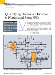
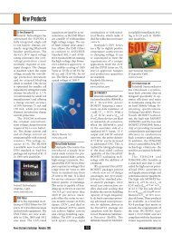
Fig. 3. The ShapeOpt program deter-<br />
0708PETWCoast_F3<br />
m<strong>in</strong>es the optimal placement of the<br />
w<strong>in</strong>d<strong>in</strong>g <strong>in</strong>side the specified bobb<strong>in</strong><br />
w<strong>in</strong>dow for a 10.6-µH <strong>in</strong>ductor.
10<br />
Gap<br />
10<br />
By choos<strong>in</strong>g the Litz strand<strong>in</strong>g and<br />
07008PET_WCoast_F4<br />
placement of the w<strong>in</strong>d<strong>in</strong>g <strong>in</strong>side of<br />
the bobb<strong>in</strong> w<strong>in</strong>dow, it is possible to<br />
m<strong>in</strong>imize w<strong>in</strong>d<strong>in</strong>g losses.<br />
A freeware simulation program<br />
called ShapeOpt allows the user to<br />
optimize the strand<strong>in</strong>g and position<strong>in</strong>g<br />
of the w<strong>in</strong>d<strong>in</strong>g <strong>in</strong>side of the available<br />
w<strong>in</strong>d<strong>in</strong>g w<strong>in</strong>dow. This program<br />
is available for use by designers at<br />
www.thayer.dartmouth.edu/<strong>in</strong>ductor/<br />
shapeopt. The program is simple to<br />
use and the <strong>in</strong>puts <strong>in</strong>clude:<br />
l Core-w<strong>in</strong>dow width and height<br />
l Bobb<strong>in</strong>-w<strong>in</strong>dow width and<br />
height<br />
l Ripple-current magnitude and<br />
frequency<br />
l Gap length<br />
l Bobb<strong>in</strong>-fill factor<br />
l Litz-wire strand diameter<br />
l Turn length<br />
l Number of turns.<br />
With this <strong>in</strong>formation as <strong>in</strong>put, the<br />
program will generate an output detail<strong>in</strong>g<br />
the field strength <strong>in</strong> the bobb<strong>in</strong><br />
w<strong>in</strong>dow as well as the ideal placement<br />
of the w<strong>in</strong>d<strong>in</strong>g <strong>in</strong> the bobb<strong>in</strong> w<strong>in</strong>dow.<br />
The program also will determ<strong>in</strong>e the<br />
total w<strong>in</strong>d<strong>in</strong>g losses and choose the<br />
number of strands necessary to fill the<br />
available w<strong>in</strong>dow area.<br />
By way of example, consider a<br />
10.6-µH <strong>in</strong>ductor operat<strong>in</strong>g at 250<br />
kHz with a 4-A rms ripple. This <strong>in</strong>ductor<br />
uses an E19/8/5 core with a<br />
10<br />
w<strong>in</strong>d<strong>in</strong>g <strong>Losses</strong><br />
9<br />
9<br />
9<br />
9<br />
8<br />
Wire<br />
8<br />
8<br />
8<br />
7<br />
7<br />
7<br />
7<br />
6<br />
6<br />
6<br />
6<br />
5<br />
5<br />
5<br />
5 Empty<br />
4<br />
4<br />
4<br />
4<br />
3<br />
3<br />
3<br />
3<br />
2<br />
2<br />
2<br />
2<br />
1<br />
1<br />
1<br />
1<br />
0<br />
0<br />
0<br />
0<br />
0 1 2 3 4 5 0 1 2 3 4 5 0 1 2 3 4 5 0 1 2 3 4 5<br />
h dimension (mm) W h dimension (mm) W h dimension (mm) W h dimension (mm)<br />
W<br />
10 kHz<br />
50 kHz 100 kHz 200 kHz<br />
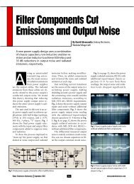
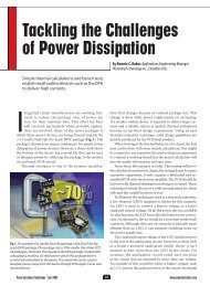
Fig. 4.The ShapeOpt program generates the optimized w<strong>in</strong>d<strong>in</strong>g placement for a s<strong>in</strong>gle<br />
<strong>in</strong>ductor as a function of operat<strong>in</strong>g frequency.<br />
10<br />
0.65-mm gap and 13 turns. With a<br />
Litz-wire strand diameter of 0.05 mm<br />
(44 AWG) selected, ShapeOpt yields<br />
an optimal result of 314 total strands<br />
and a total w<strong>in</strong>d<strong>in</strong>g loss of 0.28 W.<br />
Fig. 3 details the placement of the<br />
w<strong>in</strong>d<strong>in</strong>g <strong>in</strong>side the bobb<strong>in</strong> w<strong>in</strong>dow<br />
with the green area be<strong>in</strong>g acceptable<br />
for w<strong>in</strong>d<strong>in</strong>g and the white area be<strong>in</strong>g<br />
void space.<br />
In practice, this bobb<strong>in</strong> could<br />
quickly be prepped with a tape to mask<br />
out a rectangular cross section, which<br />
closely approximates the result shown<br />
<strong>in</strong> Fig. 3. This type of tape prep is very<br />
similar to the marg<strong>in</strong>-tape application<br />
widely used to ma<strong>in</strong>ta<strong>in</strong> creepage and<br />
clearance values to meet isolation<br />
requirements <strong>in</strong> transformers.<br />
From this simulation, it can be seen<br />
that it is not optimal to completely<br />
fill the bobb<strong>in</strong> with wire. In fact,<br />
that approach would result <strong>in</strong> much<br />
higher losses. This problem becomes<br />
even more acute as the frequency<br />
<strong>in</strong>creases.<br />
Fig. 4 is an example of an optimal<br />
solution for a s<strong>in</strong>gle <strong>in</strong>ductor<br />
as a function of frequency. As the<br />
frequency of the power <strong>in</strong>ductor<br />
<strong>in</strong>creases, the placement of the w<strong>in</strong>d<strong>in</strong>g<br />
<strong>in</strong>side the core w<strong>in</strong>dow becomes<br />
critical to obta<strong>in</strong><strong>in</strong>g the m<strong>in</strong>imumloss<br />
solution.<br />
Another topic <strong>in</strong>vestigated by<br />
Thayer researchers us<strong>in</strong>g the ShapeOpt<br />
Standard and<br />
Custom <strong>Power</strong><br />
Transformer<br />
Solutions<br />
Lam<strong>in</strong>ated and Toroidal<br />
<strong>Power</strong> Transformers,<br />
Inductors, and Custom<br />
High Frequency<br />
Magnetics<br />
Capabilities from 0.1 VA<br />
to 45 KVA<br />
PC and Chassis Mount<br />
4 RoHS-Compliant Products<br />
UL, CSA, VDE, IEC,<br />
and EN Certifi ed<br />
In-House Agency<br />
Certifi cation Program<br />
Large, F<strong>in</strong>ished Goods<br />
Inventory<br />
www.powerelectronics.com 17<br />
<strong>Power</strong> <strong>Electronics</strong> Technology July 2008<br />
4<br />
4<br />
4<br />
4<br />
4<br />
4<br />
Custom Designs Welcome!<br />
PRONTO ®<br />
24 HOUR SHIPPING!<br />
Phone: 866/239-5777<br />
Fax: 516/239-7208<br />
Signal S ignal Transformer<br />
www.signaltransformer.com<br />
sales@signaltransformer.com<br />
Signal/<strong>Power</strong> Elec. 2/4/08.<strong>in</strong>dd 1 2/4/08 9:23:48 AM
W / h W<br />
w<strong>in</strong>d<strong>in</strong>g <strong>Losses</strong><br />
6<br />
5<br />
4<br />
3<br />
2<br />
1<br />
0<br />
Fig. 5. A survey of the ratio of height-to-width for several typical E-core geometries<br />
reveals that most of the available cores and bobb<strong>in</strong>s do not have optimal shapes for<br />
power <strong>in</strong>ductors us<strong>in</strong>g gapped cores.<br />
program was the optimal ratio of<br />
07008PET_WCoast_F5<br />
core-w<strong>in</strong>d<strong>in</strong>g w<strong>in</strong>dow height to core-<br />
strand<strong>in</strong>g) and vary<strong>in</strong>g the w<strong>in</strong>dow<br />
height to w<strong>in</strong>dow breadth. When this<br />
w<strong>in</strong>d<strong>in</strong>g w<strong>in</strong>dow width. Obta<strong>in</strong><strong>in</strong>g is done, some <strong>in</strong>terest<strong>in</strong>g conclusions<br />
this optimal ratio <strong>in</strong>volves solv<strong>in</strong>g for can be drawn.<br />
the total w<strong>in</strong>d<strong>in</strong>g losses, while hold- At low frequencies, <strong>in</strong> the 1-kHz<br />
<strong>in</strong>g two factors constant (w<strong>in</strong>d<strong>in</strong>g- to 10-kHz range, the optimal ratio of<br />
Magnetics w<strong>in</strong>dow Generic perimeter Ad half and Litz-wire 11_07 1/18/08 w<strong>in</strong>dow 11:02 width AM to height Page 1is<br />
about 1. By<br />
Strip Wound Cores<br />
Tape Wound Cores<br />
Bobb<strong>in</strong> Cores<br />
Cut Cores<br />
110 Delta Drive<br />
Pittsburgh, Pa 15238<br />
Toll-Free: 1 800 245 3984<br />
Phone: 412 696 1333<br />
Fax: 412 696 0333<br />
Web: www.mag-<strong>in</strong>c.com<br />
Email: magnetics@spang.com<br />
EE ETD EC RM PQ<br />
Magnetics Hong Kong<br />
Asia Sales and Service<br />
Phone: +852 3102 9337<br />
Fax: +852 3585 1482<br />
Email: asiasales@spang.com<br />
Powder Cores<br />
Kool Mu ® Cores<br />
Molypermalloy Cores<br />
High Flux Cores<br />
XFLUX <br />
Optimal range<br />
for all<br />
frequencies<br />
the time the frequency <strong>in</strong>creases to<br />
500 kHz, the optimal ratio of width<br />
to height <strong>in</strong>creases to about 2.<br />
Compar<strong>in</strong>g this result to the ratio<br />
of height to width for several typical<br />
E-core geometries (Fig. 5), it quickly<br />
becomes apparent that most core<br />
and bobb<strong>in</strong>s available on the market<br />
today do not have optimal shapes for<br />
power <strong>in</strong>ductor designs us<strong>in</strong>g gapped<br />
cores.<br />
References<br />
1. The shaped-foil technology is<br />
patented by Dartmouth College, and<br />
West Coast Magnetics is a licensee.<br />
2. This experiment was designed by<br />
West Coast Magnetics and electrical<br />
eng<strong>in</strong>eer Jennifer Pollock, Ph.D., of<br />
Dartmouth’s Thayer School of Eng<strong>in</strong>eer<strong>in</strong>g.<br />
Professor Charles Sullivan of<br />
the Thayer School of Eng<strong>in</strong>eer<strong>in</strong>g and<br />
Ryan Goldhahn, a Duke University<br />
Ph.D. candidate, also were <strong>in</strong>volved<br />
with the experiment. PETech<br />
Ferrite Cores<br />
<strong>Power</strong> Materials<br />
High Permeability Materials<br />
Special Materials<br />
<strong>Power</strong> <strong>Electronics</strong> Technology July 2008 18<br />
www.powerelectronics.com