Spherical Mechanism Synthesis in Virtual Reality - Florida Institute ...
Spherical Mechanism Synthesis in Virtual Reality - Florida Institute ...
Spherical Mechanism Synthesis in Virtual Reality - Florida Institute ...

You also want an ePaper? Increase the reach of your titles
YUMPU automatically turns print PDFs into web optimized ePapers that Google loves.
T. J. Furlong<br />
Systems Eng<strong>in</strong>eer<br />
Creative Optics, Inc.<br />
Bedford, NH 03110<br />
tfurlong@creative-optics.com<br />
J. M. Vance<br />
Associate Professor<br />
Department of [Mechanical Eng<strong>in</strong>eer<strong>in</strong>g<br />
<strong>Virtual</strong> <strong>Reality</strong> Applications Center<br />
Iowa State University<br />
Ames, lA 50011<br />
jmvance@iastate.edu<br />
P. M. Larochelle<br />
Assistant Professor<br />
Department of IVIectianical Eng<strong>in</strong>eer<strong>in</strong>g<br />
<strong>Florida</strong> <strong>Institute</strong> of Technology<br />
Melbourne, PL 32901-6975<br />
pierre@gret2ky.me.fit.edu<br />
Introduction<br />
Erdman and Sandor (1991) def<strong>in</strong>e a mechanism as "a mechanical<br />
device that has the purpose of transferr<strong>in</strong>g motion and/or force<br />
from a source to an output." <strong>Mechanism</strong>s are generally composed<br />
of rigid l<strong>in</strong>ks connected by jo<strong>in</strong>ts. Typically, one or more l<strong>in</strong>ks are<br />
grounded to a fixed or mov<strong>in</strong>g reference frame. Mechanical eng<strong>in</strong>eers<br />
are often required to design mechanisms to perform tasks<br />
separately or as part of a larger mach<strong>in</strong>e.<br />
In 1959, Freudenste<strong>in</strong> was the first to use a computer to design<br />
mechanisms (Freudenste<strong>in</strong> and Sandor, 1959). S<strong>in</strong>ce then, a number<br />
of computer aided mechanism design packages have been<br />
developed, <strong>in</strong>clud<strong>in</strong>g KINSYN, LINCAGES, and RECSYN<br />
(Kaufman, 1978; Erdman and Gustafson, 1977; Waldron and<br />
Song, 1981).<br />
Traditionally, mechanism design has concentrated on synthesis<br />
of planar motion, but <strong>in</strong> the late 1980's people began <strong>in</strong>vestigat<strong>in</strong>g<br />
the use of computers for spatial mechanism design. Thatch and<br />
Myklebust (1988) recognized that one of the difficulties <strong>in</strong> develop<strong>in</strong>g<br />
computer-aided spatial mechanism design software was<br />
specify<strong>in</strong>g the three-dimensional <strong>in</strong>put parameters, so they developed<br />
a package called Mech<strong>in</strong> to assist designers <strong>in</strong> specify<strong>in</strong>g<br />
these <strong>in</strong>put parameters. In 1989, LINCAGES was enhanced to<br />
allow synthesis of spherical four-bars (Chen and Erdman, 1989).<br />
In 1993, McCarthy and Larochelle <strong>in</strong>troduced Sph<strong>in</strong>x, which was<br />
written expressly for synthesis of spherical four-bar l<strong>in</strong>kages (Larochelle<br />
et al, 1993). More recently, Sph<strong>in</strong>xPC has brought spherical<br />
mechanism design to the W<strong>in</strong>dows platform (Ruth and Mc<br />
Carthy, 1997).<br />
It can be difficult to make design choices <strong>in</strong> spherical mechanism<br />
synthesis because the designer must visualize and <strong>in</strong>teract <strong>in</strong><br />
three dimensions. Planar mechanism synthesis requires only twodimensional<br />
(2-D) display and <strong>in</strong>teraction, so it is well suited to the<br />
current human-computer <strong>in</strong>terface (HCI) of mouse and monitor.<br />
Sph<strong>in</strong>x and Sph<strong>in</strong>xPC require users to <strong>in</strong>teract with 3-D objects,<br />
but they still use the traditional 2-D HCI. Osborn and Vance<br />
(1995) recognized spherical mechanism synthesis as a potential<br />
application of virtual reality technology. It was believed that the<br />
3-D visualization and <strong>in</strong>teraction offered by VR could assist a<br />
designer by add<strong>in</strong>g a necessary dimension to the HCI.<br />
Contributed by the Design Automation Committee for publication <strong>in</strong> tlie Journal of<br />
Meclianical Design. Manuscript received Oct. 1998; revised Sept. 1999. Associate<br />
Technical Editor: A. Diaz.<br />
<strong>Spherical</strong> <strong>Mechanism</strong> <strong>Synthesis</strong><br />
<strong>in</strong> <strong>Virtual</strong> <strong>Reality</strong><br />
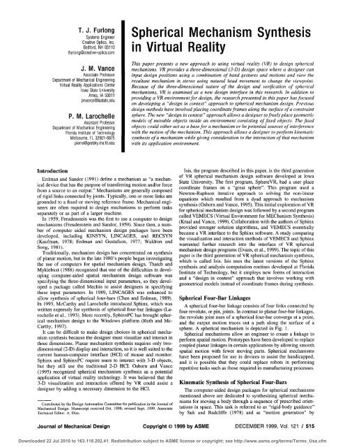
This paper presents a new approach to us<strong>in</strong>g virtual reality (VR) to design spherical<br />
mechanisms. VR provides a three-dimensional (3-D) design space where a designer can<br />
<strong>in</strong>put design positions us<strong>in</strong>g a comb<strong>in</strong>ation of hand gestures and motions and view the<br />
resultant mechanism <strong>in</strong> stereo us<strong>in</strong>g natural head movement to change the viewpo<strong>in</strong>t.<br />
Because of the three-dimensional nature of the design and verification of spherical<br />
mechanisms, VR is exam<strong>in</strong>ed as a new design <strong>in</strong>terface <strong>in</strong> this research. In addition to<br />
provid<strong>in</strong>g a VR environment for design, the research presented <strong>in</strong> this paper has focused<br />
on develop<strong>in</strong>g a "design <strong>in</strong> context" approach to spherical mechanism design. Previous<br />
design methods have <strong>in</strong>volved plac<strong>in</strong>g coord<strong>in</strong>ate frames along the surface of a constra<strong>in</strong>t<br />
sphere. The new "design <strong>in</strong> context" approach allows a designer to freely place geometric<br />
models of movable objects <strong>in</strong>side an environment consist<strong>in</strong>g of fixed objects. The fixed<br />
objects could either act as a base for a mechanism or be potential sources of <strong>in</strong>terference<br />
with the motion of the mechanism. This approach allows a designer to perform k<strong>in</strong>ematic<br />
synthesis of a mechanism while giv<strong>in</strong>g consideration to the <strong>in</strong>teraction of that mechanism<br />
with its application environment.<br />
Isis, the program described <strong>in</strong> this paper, is the third generation<br />
of VR spherical mechanism design software developed at Iowa<br />
State University. The first program. Sphere VR, had a user place<br />
coord<strong>in</strong>ate frames on a "great sphere". This program used a<br />
Newton-Raphson iterative approach to solv<strong>in</strong>g the non-l<strong>in</strong>ear<br />
equations which resulted from a dyad approach to mechanism<br />
synthesis (Osborn and Vance, 1995). This <strong>in</strong>itial exploration of VR<br />
for spherical mechanism design was followed by a second program<br />
called VEMECS (<strong>Virtual</strong> Environment for MEChanism <strong>Synthesis</strong>)<br />
(Kraal and Vance, 1999). Collaboration with the authors of Sph<strong>in</strong>x<br />
provided stronger solution algorithms, and VEMECS essentially<br />
became a VR <strong>in</strong>terface to the Sph<strong>in</strong>x software. A study compar<strong>in</strong>g<br />
the visualization and <strong>in</strong>teraction methods of VEMECS and Sph<strong>in</strong>x<br />
warranted further research <strong>in</strong>to the <strong>in</strong>terface of VR spherical<br />
mechanism design programs (Evans, et al., 1999). The topic of this<br />
paper is the third generation of VR spherical mechanism synthesis,<br />
which is called Isis. Isis uses the latest versions of the Sph<strong>in</strong>x<br />
synthesis and analysis computation rout<strong>in</strong>es developed at <strong>Florida</strong><br />
<strong>Institute</strong> of Technology, but it employs new forms of <strong>in</strong>teraction<br />
and a "design <strong>in</strong> context" approach that <strong>in</strong>volves work<strong>in</strong>g with<br />
geometrical models <strong>in</strong>stead of coord<strong>in</strong>ate frames dur<strong>in</strong>g synthesis.<br />
<strong>Spherical</strong> Four-Bar L<strong>in</strong>kages<br />
A spherical four-bar l<strong>in</strong>kage consists of four l<strong>in</strong>ks connected by<br />
four revolute, or p<strong>in</strong>, jo<strong>in</strong>ts. In contrast to planar four-bar l<strong>in</strong>kages,<br />
the revolute jo<strong>in</strong>t axes of a spherical four-bar converge at a po<strong>in</strong>t,<br />
and the output motion traces out a path along the surface of a<br />
sphere. A spherical mechanism is depicted <strong>in</strong> Fig. 1.<br />
<strong>Spherical</strong> mechanisms allow an eng<strong>in</strong>eer to create a l<strong>in</strong>kage to<br />
perform spatial motion. Prototypes have been developed to replace<br />
coupled planar l<strong>in</strong>kages <strong>in</strong> certa<strong>in</strong> applications by allow<strong>in</strong>g smooth<br />
spatial motion with fewer mov<strong>in</strong>g parts. <strong>Spherical</strong> mechanisms<br />
have been proposed for use <strong>in</strong> devices to assist the handicapped,<br />
and it is possible that they could replace robots <strong>in</strong> perform<strong>in</strong>g<br />
repetitive tasks such as those required <strong>in</strong> manufactur<strong>in</strong>g processes.<br />
K<strong>in</strong>ematic <strong>Synthesis</strong> of <strong>Spherical</strong> Four-Bars<br />
The computer-aided design packages for spherical mechanisms<br />
mentioned above are dedicated to synthesiz<strong>in</strong>g spherical mechanisms<br />
for mov<strong>in</strong>g a body through a sequence of prescribed orientations<br />
<strong>in</strong> space. This task is referred to as "rigid-body guidance"<br />
by Suh and Radcliffe (1978) and as "motion generation" by<br />
Journal of Mechanical Design Copyright © 1999 by ASME DECEMBER 1999, Vol. 121 / 515<br />
Downloaded 22 Jul 2010 to 163.118.202.41. Redistribution subject to ASME license or copyright; see http://www.asme.org/terms/Terms_Use.cfm
Fig. 1 <strong>Spherical</strong> four-bar mechanism<br />
Erdman and Sandor (1977). Sph<strong>in</strong>x, Sph<strong>in</strong>xPC, VEMECS, and Isis<br />
are dedicated to synthesiz<strong>in</strong>g mechanisms which guide a body<br />
through four orientations.<br />
Once the four orientations are prescribed, the spherical generalization<br />
of Burmester's planar theory is employed to determ<strong>in</strong>e<br />
the set of all mechanisms which accomplish the task (Larochelle et<br />
al., 1993). The result of Burmester's solution to four orientations<br />
are two cubic cones referred to as the fixed axis cone and the<br />
mov<strong>in</strong>g axis cone. The fixed axis cone is the set of all fixed axes<br />
of spherical RR dyads that will guide the mov<strong>in</strong>g body through the<br />
four prescribed orientations. The mov<strong>in</strong>g axis cone is the set of<br />
correspond<strong>in</strong>g mov<strong>in</strong>g axes of the spherical RR dyads. A spherical<br />
four-bar mechanism may be viewed as an assemblage of two<br />
spherical RR dyads, where a dyad consists of a fixed and mov<strong>in</strong>g<br />
axis pair. Hence, we have a two-dimensional solution set, and<br />
select<strong>in</strong>g two po<strong>in</strong>ts from either of the cones def<strong>in</strong>es the two dyads<br />
which are then assembled to def<strong>in</strong>e a spherical four-bar mechanism<br />
that accomplishes the task.<br />
The fixed and mov<strong>in</strong>g axis cones def<strong>in</strong>e all of the mechanisms<br />
which will guide a body through the four orientations. However,<br />
Burmester's solution is not sufficient to arrive at a practical solution.<br />
Further analyses must be perforrhed tq exam<strong>in</strong>e the type of<br />
mechanism, whether or not the mechanism is <strong>in</strong>put drivable, and if<br />
the four orientations are reached <strong>in</strong> the desired order. These performance<br />
criteria are collectively referred to as solution rectification<br />
by Waldron and Strong (1978). Sph<strong>in</strong>x, Sph<strong>in</strong>xPC, and Isis<br />
perform the necessary solution rectification and present the results<br />
as a "type map" (Murray and McCarthy, 1995). The type map<br />
displays all of the solutions generated by Burmester's theory<br />
color-coded by mechanism type. Moreover, the type map is<br />
equipped with a filter to display only those mechanisms that are<br />
<strong>in</strong>put drivable and reach the orientations <strong>in</strong> the desired order. The<br />
result is a tool which enables the designer to select a mechanism<br />
which is a practical solution to the prescribed task.<br />
The Isis Environment<br />
Peripherals. Isis can be used <strong>in</strong> a head-mounted display<br />
(HMD), on a projection screen us<strong>in</strong>g CrystalEyes stereo shutter<br />
glasses, or <strong>in</strong> Iowa State University's C2, a CAVE''^"-like<br />
surround-screen virtual reality room. Fakespace PINCH Gloves<br />
may be used for <strong>in</strong>teraction <strong>in</strong> conjunction with any of the display<br />
devices mentioned above. PINCH Gloves register contact between<br />
a user's f<strong>in</strong>gers, allow<strong>in</strong>g gestural <strong>in</strong>put to the program. Ascension<br />
Flock of Birds magnetic trackers are used to track the motion of a<br />
user's head and hand. Figure 2 shows a user <strong>in</strong>teract<strong>in</strong>g with the<br />
Isis software <strong>in</strong> the C2 virtual reality environment. The user can<br />
Fig. 2 Isis displayed In the C2 virtual environment<br />
also <strong>in</strong>teract with the program us<strong>in</strong>g a standard mouse and monitor<br />
when VR peripherals are not available.<br />
Because of the 3-D nature of specify<strong>in</strong>g desired positions and of<br />
verify<strong>in</strong>g the resultant mechanism design, the immersive nature of<br />
the C2 and the HMD greatly enhance the design experience of the<br />
user of Isis. It was our experience that project<strong>in</strong>g Isis on a one wall<br />
screen or <strong>in</strong>teract<strong>in</strong>g with Isis us<strong>in</strong>g a standard mouse and monitor<br />
was <strong>in</strong>sufficient to provide the truly immersive virtual environment<br />
which is needed for spherical mechanism design. So, although the<br />
program can be used with many different <strong>in</strong>terfaces, the C2 or the<br />
HMD is preferred.<br />
Interaction. Three basic PINCH Glove gestures are used <strong>in</strong> the<br />
program, and the mean<strong>in</strong>g of each gesture is kept consistent<br />
throughout. One gesture is used for grasp<strong>in</strong>g an object and mov<strong>in</strong>g<br />
it with<strong>in</strong> the space. A second gesture selects menu items and is<br />
used for <strong>in</strong>teractions that fall outside of the standard grasp and<br />
move mode. The third basic gesture is used to <strong>in</strong>crement through<br />
the steps that must be taken to synthesize a mechanism. Each<br />
gesture requires the user to simply touch one f<strong>in</strong>ger to the thumb.<br />
To provide higher level functionality to Isis, a 3-D menu system<br />
was created. Menus are used for file manipulation and for choos<strong>in</strong>g<br />
options that would be <strong>in</strong>convenient to assign to a s<strong>in</strong>gle gesture.<br />
The menus are virtual objects consist<strong>in</strong>g of text items and a menu<br />
bar. The menus may be grasped by the user's virtual hand and<br />
repositioned <strong>in</strong> space. Po<strong>in</strong>t<strong>in</strong>g at a menu item and gestur<strong>in</strong>g<br />
appropriately selects that item. The program's ma<strong>in</strong> menu is depicted<br />
<strong>in</strong> Fig. 3.<br />
Design Methodology. The Isis environment beg<strong>in</strong>s as an<br />
empty space. This is a departure from previous spherical mechanism<br />
design programs, which beg<strong>in</strong> with a large sphere as the only<br />
la<strong>in</strong> ienu<br />
F m<br />
m<br />
I le<br />
Opt i ons<br />
Pos Synth<br />
L i nkaae<br />
Fig. 3 Isis ma<strong>in</strong> menu<br />
516 / Vol. 121, DECEMBER 1999 Transactions of the ASME<br />
Downloaded 22 Jul 2010 to 163.118.202.41. Redistribution subject to ASME license or copyright; see http://www.asme.org/terms/Terms_Use.cfm
Fig. 4 Chair base and tray <strong>in</strong>stances<br />
object <strong>in</strong> the design environment. The goal of the <strong>in</strong>itial empty<br />
space is to provide the user with a completely customizable design<br />
environment that is not biased by the presence of a design sphere.<br />
In Isis, a sphere is only <strong>in</strong>troduced <strong>in</strong>to the environment when it is<br />
necessary to show the spherical constra<strong>in</strong>t that a user has created<br />
by the placement of design positions. In Isis, emphasis is placed on<br />
the spatial task, not on <strong>in</strong>teract<strong>in</strong>g with a design sphere which has<br />
no physical counterpart <strong>in</strong> the f<strong>in</strong>al design.<br />
When design<strong>in</strong>g a mechanism, the user has the option of work<strong>in</strong>g<br />
with geometric models of actual parts. For example, the lecture<br />
hall chair <strong>in</strong> Fig. 4 was loaded <strong>in</strong> as the base model for the<br />
mechanism design. The user may also use a geometry file to def<strong>in</strong>e<br />
a position synthesis task. The tray tables <strong>in</strong> Fig. 4 are movable<br />
<strong>in</strong>stances of a model brought <strong>in</strong>to Isis for this purpose. Geometry<br />
files can come from CAD packages such as AutoCAD and Pro/<br />
Eng<strong>in</strong>eer, and from model<strong>in</strong>g packages such as MultiGen and 3D<br />
Studio.<br />
Once a movable geometry has been loaded, the user may grasp<br />
it and freely place it <strong>in</strong> space. To make it easier to place the<br />
geometry precisely, the user can turn on the option to constra<strong>in</strong><br />
movement to either the X-Y, X-Z, or Y-Z plane of the global<br />
coord<strong>in</strong>ate frame. To reduce visual clutter, the geometry def<strong>in</strong><strong>in</strong>g<br />
a position synthesis task is rendered as semi-transparent. An <strong>in</strong>stance<br />
of the geometry becomes opaque when it is manipulated,<br />
allow<strong>in</strong>g the user to concentrate on that particular position.<br />
Once the user has placed one position of the movable geometry,<br />
a second <strong>in</strong>stance is created and moved to another position <strong>in</strong><br />
space. Usually the first and second positions signify the desired<br />
beg<strong>in</strong>n<strong>in</strong>g and end<strong>in</strong>g positions for the motion of the l<strong>in</strong>kage. The<br />
first position is placed freely <strong>in</strong> space. To guarantee purely spherical<br />
motion between the first two positions, the second position is<br />
constra<strong>in</strong>ed such that the z-axes of the first two mov<strong>in</strong>g frames<br />
<strong>in</strong>tersect. Once the first two positions have been placed, the spherical<br />
constra<strong>in</strong>t surface is def<strong>in</strong>ed and displayed. The rema<strong>in</strong><strong>in</strong>g two<br />
positions are conf<strong>in</strong>ed to the sphere def<strong>in</strong>ed by the first two<br />
position choices.<br />
After four positions are placed, the user selects the desired order<br />
<strong>in</strong> which the mechanism should move through the positions. At<br />
this po<strong>in</strong>t, the fixed and mov<strong>in</strong>g axis cones or the type map may be<br />
generated. Isis gives the position <strong>in</strong>formation to the Sph<strong>in</strong>x computation<br />
rout<strong>in</strong>es, and the Sph<strong>in</strong>x algorithms return the appropriate<br />
solution <strong>in</strong>formation.<br />
The ability to work with geometric models is a feature that sets<br />
Isis apart from previous approaches to design. Motion synthesis<br />
with<strong>in</strong> the context of its application allows users to see right away<br />
whether or not a mechanism is feasible for its <strong>in</strong>tended use.<br />
Unwanted collisions between objects can <strong>in</strong>stantly be seen, and the<br />
design can be altered immediately. Figure 4 depicts four <strong>in</strong>stances<br />
of a tray model placed around a chair that will act as a base for a<br />
mechanism. It can clearly be seen that the <strong>in</strong>tended task of the<br />
Journal of Mechanical Design<br />
Fig. 5 Tray positions <strong>in</strong> sph<strong>in</strong>x<br />
mechanism <strong>in</strong> this example will be to move the tray from its<br />
work<strong>in</strong>g position to its stowed location. This would not be evident<br />
if a user were to work exclusively with coord<strong>in</strong>ate frames, as can<br />
be seen <strong>in</strong> Fig. 5, which shows the same four positions <strong>in</strong> Sph<strong>in</strong>x.<br />
The design emphasis <strong>in</strong> Isis is placed on def<strong>in</strong><strong>in</strong>g the task of<br />
mov<strong>in</strong>g the tray table, as opposed to plac<strong>in</strong>g coord<strong>in</strong>ate frames on<br />
a constra<strong>in</strong>t sphere.<br />
Figure 6 shows another example of a spherical motion synthesis<br />
task that benefits from us<strong>in</strong>g geometric models. Here, a designer<br />
creates a mechanism that ensures that the soda can will travel<br />
along a path that is free of obstruction.<br />
Figure 7 shows the prototype mechanism which was constructed<br />
based on the design created <strong>in</strong> the virtual environment for the soda<br />
can task.<br />
Cones. Sph<strong>in</strong>x rout<strong>in</strong>es calculate the fixed and mov<strong>in</strong>g axis<br />
cones, and Isis displays these as red and blue 3-D curves. Users of<br />
Isis are able to see l<strong>in</strong>ks appear as selections are made on the<br />
cones. When two l<strong>in</strong>ks are chosen, a coupler curve appears, and a<br />
message box opens to tell the user what type of l<strong>in</strong>kage has been<br />
synthesized. The user may then move the axes to see how the<br />
l<strong>in</strong>kage and coupler curve change. Figure 8 shows a user creat<strong>in</strong>g<br />
a l<strong>in</strong>k by pick<strong>in</strong>g on the red fixed axis cone.<br />
Type Map. As stated previously, a type map is a 2-D plot that<br />
displays the solutions generated by Burmester's theory which are<br />
color-coded by mechanism type. Isis takes advantage of the VR<br />
display and br<strong>in</strong>gs the type map <strong>in</strong>to three dimensions. L<strong>in</strong>kages<br />
Fig. 6 Soda can tasl<<br />
DECEMBER 1999, Vol. 121 / 517<br />
Downloaded 22 Jul 2010 to 163.118.202.41. Redistribution subject to ASME license or copyright; see http://www.asme.org/terms/Terms_Use.cfm
Fig. 7 Actual soda can mechanism<br />
that pass the test of <strong>in</strong>put drivability and reach the orientations <strong>in</strong><br />
the desired order are shown on a plane above the whole solution<br />
set, and those solutions that do not pass the tests are darkened on<br />
the type map. The result of this is a display that shows good and<br />
bad mechanisms together, with the good mechanisms easily dist<strong>in</strong>guishable<br />
from the undesirable ones.<br />
A user selects a po<strong>in</strong>t <strong>in</strong> a colored region based on the type of<br />
l<strong>in</strong>kage that he or she is try<strong>in</strong>g to synthesize, and the l<strong>in</strong>kage<br />
correspond<strong>in</strong>g to that po<strong>in</strong>t appears along with <strong>in</strong>formation about<br />
the l<strong>in</strong>kage type and fold<strong>in</strong>g condition. In the example shown <strong>in</strong><br />
Fig. 9, one can see the type map, which displays the better<br />
mechanisms as areas of bright blue and yellow. Additionally, a<br />
complete mechanism result<strong>in</strong>g from the type map choice is shown<br />
with its coupler curve depicted <strong>in</strong> yellow. To the right of the<br />
mechanism is a message box conta<strong>in</strong><strong>in</strong>g confirmation of the mechanism<br />
type that has been chosen and <strong>in</strong>formation about the fold<strong>in</strong>g<br />
condition of the Unkage.<br />
Design Verification. Once a mechanism has been synthesized<br />
<strong>in</strong> Isis, it may be animated to verify that it completes the required<br />
task. The transparent positions rema<strong>in</strong> present, and an opaque<br />
<strong>in</strong>stance of the mov<strong>in</strong>g geometry moves along with the coupler<br />
l<strong>in</strong>k of the mechanism. Designers can observe how smoothly a<br />
mechanism moves, and they can see whether or not objects will<br />
collide dur<strong>in</strong>g motion of the mechanism. Because of the availability<br />
of head track<strong>in</strong>g <strong>in</strong> the virtual reality environment, designers<br />
are allowed to move around the design and <strong>in</strong>vestigate the motion<br />
Fig. 8 Pick<strong>in</strong>g cones<br />
518 / Vol. 121, DECEMBER 1999<br />
Fig. 9 Type map Interaction<br />
of the mechanism from many different angles. It is very <strong>in</strong>tuitive<br />
to <strong>in</strong>vestigate the operation of the mechanism because the designer's<br />
viewpo<strong>in</strong>t changes accord<strong>in</strong>g to natural human motions.<br />
File Manipulation. After a user has synthesized a mechanism,<br />
an output file can be generated. The file written by Isis is an<br />
augmented Sph<strong>in</strong>x file, which is readable by Sph<strong>in</strong>x. The augmented<br />
file conta<strong>in</strong>s <strong>in</strong>formation such as sphere radius, sphere<br />
position, geometric model filenames, and geometric model positions.<br />
This <strong>in</strong>formation is used to reconstruct the "design-<strong>in</strong>context"<br />
environment when a file is loaded <strong>in</strong>to Isis. Standard<br />
(non-augmented) Sph<strong>in</strong>x files can also be loaded <strong>in</strong>to Isis. When<br />
load<strong>in</strong>g a standard Sph<strong>in</strong>x file, Isis will use a default sphere radius<br />
and position, and it will not attempt to load any geometric models.<br />
Summary of Program Usage. Figure 10 shows a flowchart<br />
summariz<strong>in</strong>g the procedure taken to synthesize a spherical mechanism<br />
<strong>in</strong> Isis. Parallel portions of the flowchart <strong>in</strong>dicate optional<br />
paths. For example, a user may br<strong>in</strong>g <strong>in</strong> geometry or simply use<br />
coord<strong>in</strong>ate frames to def<strong>in</strong>e a synthesis task. Alternatively, a mechanism<br />
previously saved from Sph<strong>in</strong>x or Isis may be loaded <strong>in</strong>to the<br />
program. To generate or redesign a mechanism, either cones or a<br />
type map may be used. Users may alter positions and regenerate<br />
the cones or type map until a good solution is obta<strong>in</strong>ed.<br />
In Fig. 10, the gray boxes <strong>in</strong>dicate parts of the program that<br />
utilize Sph<strong>in</strong>x functions. Some of the Sph<strong>in</strong>x functions have rema<strong>in</strong>ed<br />
untouched, but others have been modified to fill Isis data<br />
structures and create geometry for display by WorldToolKit.<br />
Conclusions<br />
The presence of virtual reality <strong>in</strong> eng<strong>in</strong>eer<strong>in</strong>g design is grow<strong>in</strong>g,<br />
and the work presented here is a reflection of that. The visualization<br />
benefits of VR have long been known, and the modes of<br />
<strong>in</strong>teraction <strong>in</strong> VR are converg<strong>in</strong>g towards a naturalistic <strong>in</strong>terface.<br />
Isis is written for use with the latest VR devices, and <strong>in</strong>teraction<br />
with<strong>in</strong> the program is not an adaptation of a workstation <strong>in</strong>terface.<br />
It is written expressly to be a virtual environment <strong>in</strong> which <strong>in</strong>teraction<br />
and view<strong>in</strong>g are <strong>in</strong>tuitive. The 3-D display of a mechanism,<br />
the availability of <strong>in</strong>formation about the mechanism, and the<br />
"design <strong>in</strong> context" methodology present a complete picture of a<br />
design, so there are fewer surprises when a mechanism is brought<br />
from the virtual world to the real world.<br />
Future Work<br />
New methods of task specification are be<strong>in</strong>g developed at <strong>Florida</strong><br />
Tech. The research is focus<strong>in</strong>g on novel methods for prescrib<strong>in</strong>g<br />
the desired positions of a mov<strong>in</strong>g body. These new methods are<br />
<strong>in</strong>tended to enhance the "design <strong>in</strong> context" capabilities of Isis.<br />
One method allows a user to place any number of positions freely<br />
<strong>in</strong> space and then the optimal design sphere is automatically<br />
determ<strong>in</strong>ed as well as the correspond<strong>in</strong>g positions on the sphere.<br />
Another approach allows the user to specify one position of the<br />
Transactions of the ASME<br />
Downloaded 22 Jul 2010 to 163.118.202.41. Redistribution subject to ASME license or copyright; see http://www.asme.org/terms/Terms_Use.cfm
START<br />
Load Base Geometry<br />
i :<br />
Load Movable Geometry Create Coord<strong>in</strong>ate Frame<br />
Reposition Coord<strong>in</strong>ate Frame<br />
Relative to Movable Geometry<br />
1<br />
Adjust Positions<br />
Place Position 1<br />
Place Position 2, Orientation<br />
Constra<strong>in</strong>ed to Def<strong>in</strong>e Sphere<br />
Place Positions 3 and 4,<br />
Constra<strong>in</strong>ed to Sphere<br />
31<br />
mov<strong>in</strong>g body which is to be realized exactly and a set of positions<br />
which serve to guide or shape the motion as desired. Aga<strong>in</strong>, the<br />
optimal design sphere and the correspond<strong>in</strong>g positions are automatically<br />
computed. The goal of this research is to allow the<br />
designer to specify the task <strong>in</strong> the physical workspace without<br />
impos<strong>in</strong>g the artificial constra<strong>in</strong>ts associated with a design sphere.<br />
Incorporation of this research <strong>in</strong>to Isis is a planned future improvement.<br />
Another feature planned for Isis is automatic collision detection<br />
between fixed and movable geometry. This could be done by<br />
build<strong>in</strong>g upon the swept volume research of L<strong>in</strong>g and Hu (1997) or<br />
by us<strong>in</strong>g a collision detection library such as RAPID (Gottschalk<br />
et al., 1996). Presently the user has to visually <strong>in</strong>spect the mechanism<br />
to check for collisions, but check<strong>in</strong>g collisions with the<br />
computer and restrict<strong>in</strong>g the motion of the mechanism appropriately<br />
would relieve the designer of some work.<br />
While <strong>in</strong>teraction <strong>in</strong> Isis is fairly <strong>in</strong>tuitive, plac<strong>in</strong>g the <strong>in</strong>termediate<br />
positions <strong>in</strong> their desired orientation while constra<strong>in</strong>ed to the<br />
design sphere needs improvement. The difficulty lies <strong>in</strong> the fact<br />
that although the visual representation of the movable geometry is<br />
constra<strong>in</strong>ed to the spherical design surface, the user's hand is not<br />
constra<strong>in</strong>ed to any surface and is free to move <strong>in</strong> the 3-D design<br />
space. Therefore, <strong>in</strong> this implementation of Isis, precise position<strong>in</strong>g<br />
of the movable geometry is still not natural and the manipulation<br />
of the geometry <strong>in</strong> these <strong>in</strong>stances is not yet <strong>in</strong>tuitive. Other<br />
methods of <strong>in</strong>teractively plac<strong>in</strong>g these positions while constra<strong>in</strong>ed<br />
to the design sphere need to be <strong>in</strong>vestigated.<br />
The real proof of the effectiveness of an environment such as<br />
Isis will be us<strong>in</strong>g it to design practical mechanisms. Material<br />
handl<strong>in</strong>g processes are be<strong>in</strong>g exam<strong>in</strong>ed to see if an Isis-designed<br />
mechanism can be effective <strong>in</strong> such an environment. Other uses for<br />
spherical four-bar mechanisms are be<strong>in</strong>g sought as well. Apply<strong>in</strong>g<br />
Isis to practical synthesis tasks will enable designers to evaluate<br />
Load <strong>Mechanism</strong><br />
Save <strong>Mechanism</strong> = Sph<strong>in</strong>x Rout<strong>in</strong>es Used<br />
Fig. 10 Diagram of program usage<br />
the effectiveness of the VR implementation of our "design <strong>in</strong><br />
context" approach to spherical mechanism design.<br />
References<br />
Chen, X. Q., and Erdman, A. G., "Systematic <strong>Synthesis</strong> of <strong>Spherical</strong> Four-Bar<br />
<strong>Mechanism</strong>s," First National Applied <strong>Mechanism</strong>s and Robotics Conference, University<br />
of C<strong>in</strong>c<strong>in</strong>nati, 89AMR-78-5, Nov. 1989.<br />
Erdman, A. G., and Gustafson, J. E., "LINCAGES: L<strong>in</strong>kages INteractive Computer<br />
Analysis and Graphically Enhanced <strong>Synthesis</strong> Package," ASME paper 77-DET-5,<br />
presented at ASME Design Eng<strong>in</strong>eer<strong>in</strong>g Technical Conference, Sept. 26-30, 1977.<br />
Erdman, A., and Sander, G. N., <strong>Mechanism</strong> Design: Analysis and <strong>Synthesis</strong>,<br />
Prentice Hall, Englewood Cliffs, New Jersey, 1991.<br />
Erdman, A., and Sandor, G. N., Advanced <strong>Mechanism</strong> Design: Analysis and<br />
<strong>Synthesis</strong>, Prentice Hall, Englewood Cliffs, New Jersey, 1997.<br />
Evans, P. T., Vance, J. M., and Dark, V. J., "Assess<strong>in</strong>g the Effectiveness of<br />
Traditional and <strong>Virtual</strong> <strong>Reality</strong> Interfaces <strong>in</strong> <strong>Spherical</strong> <strong>Mechanism</strong> Design," ASME<br />
JOURNAL OF MECHANICAL DESIGN, <strong>in</strong> press, 1999.<br />
Freudenste<strong>in</strong>, F., and Sandor, G. N., "<strong>Synthesis</strong> of Path-Generat<strong>in</strong>g <strong>Mechanism</strong>s by<br />
Means of a Programmed Digital Computer," ASME Journal of Eng<strong>in</strong>eer<strong>in</strong>g for<br />
Industry Vol. 81B, No. 2 pp. 159-168, May 1959.<br />
Gottschalk, S., L<strong>in</strong>, M. C., and Manocha, D., "OBB-Tree: A Hierarchical Structure<br />
for Rapid Interference Detection," Proceed<strong>in</strong>gs of ACM SIGGRAPH '96, pp. 171-<br />
180, New Orleans, LA, 1996.<br />
Kaufman, R. E., "<strong>Mechanism</strong> Design by Computer," Mach<strong>in</strong>e Design, Vol. 50, No.<br />
24 pp. 94-100, Oct. 26, 1978.<br />
Kraal, J. C, and Vance, J. M., "VEMECS: A <strong>Virtual</strong> <strong>Reality</strong> Interface for <strong>Spherical</strong><br />
<strong>Mechanism</strong> Design," submitted to The Journal of Eng<strong>in</strong>eer<strong>in</strong>g De.iign, 1999.<br />
Larochelle, P. M., Dooley, J. R., Murray, A. P., and McCarthy, J. M., "SPHINX:<br />
Software for Synthesiz<strong>in</strong>g <strong>Spherical</strong> 4R <strong>Mechanism</strong>s," NSF Design and Manufactur<strong>in</strong>g<br />
Systems Conference, 1, pp. 607-611, Jan. 1993.<br />
L<strong>in</strong>g, Z., and Hu, Z., "Use of Swept Volumes <strong>in</strong> die Design of Interference Free Spatial<br />
<strong>Mechanism</strong>s," <strong>Mechanism</strong> and Mach<strong>in</strong>e Theory, Vol. 32, No. 4, pp. 459-476, 1997.<br />
McCarthy, J. M., "The <strong>Synthesis</strong> of Planar RR and Spatial CC Cha<strong>in</strong>s and the<br />
Equation of a Triangle," ASME JOURNAL OF MECHANICAL DESIGN, Vol. 117(B), pp.<br />
101-106, June 1995.<br />
Murray, A., and McCarthy, J., "A L<strong>in</strong>kage Type Map for <strong>Spherical</strong> 4 Position<br />
<strong>Synthesis</strong>," Proceed<strong>in</strong>gs of the 1995 ASME Design Technical Conferences, Boston,<br />
MA, DE-82:833-838, Sept. 1995.<br />
Osborn, S. W., and Vance, J. M., "A <strong>Virtual</strong> Environment for Synthesiz<strong>in</strong>g<br />
Journal of Mechanical Design DECEMBER 1999, Vol. 121 / 519<br />
Downloaded 22 Jul 2010 to 163.118.202.41. Redistribution subject to ASME license or copyright; see http://www.asme.org/terms/Terms_Use.cfm
<strong>Spherical</strong> Four-Bar <strong>Mechanism</strong>s," Proceed<strong>in</strong>gs of the 1995 Design Eng<strong>in</strong>eer<strong>in</strong>g Spatial <strong>Mechanism</strong> Design," IEEE Computer Graphics and Applications, 8, pp.<br />
Technical Conferences. Boston, MA, DE-83:885-892, Sept. 1995. 26-38, March 1988.<br />
Ruth, D. A., and McCarthy, J. M., "Sph<strong>in</strong>xPC: An Implementation of Four Position Waldron, K. J., and Song, S. M., "Theoretical and Numerical Improvements to an<br />
<strong>Synthesis</strong> for Planar and <strong>Spherical</strong> 4R L<strong>in</strong>kages," Proceed<strong>in</strong>gs of the 1997 ASME Interactive L<strong>in</strong>kage Design Program, RECSYN," Proceed<strong>in</strong>gs of the Seventh Applied<br />
Design Eng<strong>in</strong>eer<strong>in</strong>g Technical Conferences, Sacramento, CA, September 1997. <strong>Mechanism</strong>s Conference, Kansas City, MO, Dec. 1981.<br />
Suh, C. H., and Radchffe, C. W., K<strong>in</strong>ematics and <strong>Mechanism</strong> Design, John Wiley Waldron, K. J., and Strong, R. T., "Improved Solutions of the Branch and Order<br />
& Sons, New York, 1978. Problems of Burmester L<strong>in</strong>kage <strong>Synthesis</strong>," <strong>Mechanism</strong> and Mach<strong>in</strong>e Theory, Vol.<br />
Thatch, B. R., and Myklebust, A., "A PHIGS-Based Graphics Input Interface for 13, No. 2 pp. 199-207, 1978.<br />
520 / Vol. 121, DECEMBER 1999 Transactions of the ASME<br />
Downloaded 22 Jul 2010 to 163.118.202.41. Redistribution subject to ASME license or copyright; see http://www.asme.org/terms/Terms_Use.cfm