Spherical Mechanism Synthesis in Virtual Reality - Florida Institute ...
Spherical Mechanism Synthesis in Virtual Reality - Florida Institute ...
Spherical Mechanism Synthesis in Virtual Reality - Florida Institute ...

You also want an ePaper? Increase the reach of your titles
YUMPU automatically turns print PDFs into web optimized ePapers that Google loves.
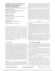
SPHERICAL MECHANISM SYNTHESIS IN VIRTUAL REALITY<br />
Todd J. Furlong<br />
Judy M. Vance<br />
Department of Mechanical Eng<strong>in</strong>eer<strong>in</strong>g<br />
Iowa Center for Emerg<strong>in</strong>g Manufactur<strong>in</strong>g<br />
Technology<br />
Iowa State University<br />
Ames, Iowa 50011<br />
tfurlong@icemt.iastate.edu<br />
jmvance@icemt.iastate.edu<br />
ABSTRACT<br />
This paper presents a new approach to us<strong>in</strong>g virtual reality<br />
(VR) to design spherical mechanisms. VR provides a three<br />
dimensional design space where a designer can <strong>in</strong>put design<br />
positions us<strong>in</strong>g a comb<strong>in</strong>ation of hand gestures and motions and<br />
view the resultant mechanism <strong>in</strong> stereo us<strong>in</strong>g natural head<br />
movement to change the viewpo<strong>in</strong>t. Because of the three<br />
dimensional nature of the design and verification of spherical<br />
mechanisms, VR is exam<strong>in</strong>ed as a new design <strong>in</strong>terface <strong>in</strong> this<br />
research. In addition to provid<strong>in</strong>g a VR environment for<br />
design, the research presented <strong>in</strong> this paper has focused on<br />
develop<strong>in</strong>g a “design <strong>in</strong> context” approach to spherical<br />
mechanism design. Previous design methods have <strong>in</strong>volved<br />
plac<strong>in</strong>g coord<strong>in</strong>ate frames along the surface of a constra<strong>in</strong>t<br />
sphere. The new “design <strong>in</strong> context” approach allows a<br />
designer to freely place geometric models of movable objects<br />
<strong>in</strong>side an environment consist<strong>in</strong>g of fixed objects. The fixed<br />
objects could either act as a base for a mechanism or be<br />
potential sources of <strong>in</strong>terference with the motion of the<br />
mechanism. This approach allows a designer to perform<br />
k<strong>in</strong>ematic synthesis of a mechanism while giv<strong>in</strong>g consideration<br />
to the <strong>in</strong>teraction of that mechanism with its application<br />
environment.<br />
INTRODUCTION<br />
Erdman and Sandor (1991) def<strong>in</strong>e a mechanism as “a<br />
mechanical device that has the purpose of transferr<strong>in</strong>g motion<br />
and/or force from a source to an output.” <strong>Mechanism</strong>s are<br />
generally composed of rigid l<strong>in</strong>ks connected by jo<strong>in</strong>ts.<br />
Typically, one or more l<strong>in</strong>ks are grounded to a fixed or mov<strong>in</strong>g<br />
Proceed<strong>in</strong>gs of DETC98:<br />
Design Automation Conference<br />
September 13-16, 1998, Atlanta, Georgia<br />
DETC98/DAC-5584<br />
Pierre M. Larochelle<br />
Department of Mechanical Eng<strong>in</strong>eer<strong>in</strong>g<br />
<strong>Florida</strong> <strong>Institute</strong> of Technology<br />
Melbourne, <strong>Florida</strong> 32901-6975<br />
pierre@gretzky.me.fit.edu<br />
reference frame. Mechanical eng<strong>in</strong>eers are often required to<br />
design mechanisms to perform tasks separately or as part of a<br />
larger mach<strong>in</strong>e.<br />
In 1959, Freudenste<strong>in</strong> was the first to use a computer to<br />
design mechanisms (Freudenste<strong>in</strong> and Sandor, 1959). S<strong>in</strong>ce<br />
then, a number of computer aided mechanism design packages<br />
have been developed, <strong>in</strong>clud<strong>in</strong>g KINSYN, LINCAGES, and<br />
RECSYN (Kaufman, 1978; Erdman and Gustafson, 1977,<br />
Waldron and Song, 1981).<br />
Traditionally, mechanism design has concentrated on<br />
synthesis of planar motion, but <strong>in</strong> the late 1980’s people began<br />
<strong>in</strong>vestigat<strong>in</strong>g the use of computers for spatial mechanism<br />
design. Thatch and Myklebust (1988) recognized that one of the<br />
difficulties <strong>in</strong> develop<strong>in</strong>g computer-aided spatial mechanism<br />
design software was specify<strong>in</strong>g the three-dimensional <strong>in</strong>put<br />
parameters, so they developed a package called Mech<strong>in</strong> to assist<br />
designers <strong>in</strong> specify<strong>in</strong>g these <strong>in</strong>put parameters. In 1989,<br />
LINCAGES was enhanced to allow synthesis of spherical fourbars<br />
(Chen and Erdman, 1989). In 1993, McCarthy and<br />
Larochelle <strong>in</strong>troduced Sph<strong>in</strong>x, which was written expressly for<br />
synthesis of spherical four-bar l<strong>in</strong>kages (Larochelle et al, 1993).<br />
More recently, Sph<strong>in</strong>xPC has brought spherical mechanism<br />
design to the W<strong>in</strong>dows platform (Ruth and McCarthy, 1997).<br />
It can be difficult to make design choices <strong>in</strong> spherical<br />
mechanism synthesis because the designer must visualize and<br />
<strong>in</strong>teract <strong>in</strong> three dimensions. Planar mechanism synthesis<br />
requires only two-dimensional display and <strong>in</strong>teraction, so it is<br />
well suited to the current human-computer <strong>in</strong>terface (HCI) of<br />
mouse and monitor. Sph<strong>in</strong>x and Sph<strong>in</strong>xPC require users to<br />
<strong>in</strong>teract with 3-D objects, but they still use the traditional 2-D<br />
HCI. Osborn and Vance (1995) recognized spherical<br />
1 Copyright © 1998 by ASME
mechanism synthesis as a potential application of virtual reality<br />
technology. It was believed that the 3-D visualization and<br />
<strong>in</strong>teraction offered by VR could assist a designer by add<strong>in</strong>g a<br />
necessary dimension to the HCI.<br />
Isis, the program described <strong>in</strong> this paper, is the third<br />
generation of VR spherical mechanism design software<br />
developed at Iowa State University. The first program,<br />
SphereVR, had a user place coord<strong>in</strong>ate frames on a “great<br />
sphere”, and it used a Newton-Raphson iterative approach to<br />
solv<strong>in</strong>g the non-l<strong>in</strong>ear equations arrived at from a dyad<br />
approach to synthesis (Osborn and Vance, 1995). This <strong>in</strong>itial<br />
exploration of VR for spherical mechanism design was<br />
followed by a second program called VEMECS (<strong>Virtual</strong><br />
Environment for MEChanism <strong>Synthesis</strong>) (Kraal, 1996).<br />
Collaboration with the authors of Sph<strong>in</strong>x provided stronger<br />
solution algorithms, and VEMECS essentially became a VR<br />
<strong>in</strong>terface to the Sph<strong>in</strong>x software. A study compar<strong>in</strong>g the<br />
visualization and <strong>in</strong>teraction methods of VEMECS and Sph<strong>in</strong>x<br />
warranted further research <strong>in</strong>to the <strong>in</strong>terface of VR spherical<br />
mechanism design programs (Evans, 1997). The topic of this<br />
paper is the third generation of VR spherical mechanism<br />
synthesis, which is called Isis. Isis uses the latest versions of<br />
the Sph<strong>in</strong>x synthesis and analysis computation rout<strong>in</strong>es<br />
developed at <strong>Florida</strong> <strong>Institute</strong> of Technology, but it employs<br />
new forms of <strong>in</strong>teraction and a “design <strong>in</strong> context” approach<br />
that <strong>in</strong>volves work<strong>in</strong>g with geometrical models <strong>in</strong>stead of<br />
coord<strong>in</strong>ate frames dur<strong>in</strong>g synthesis.<br />
SPHERICAL FOUR-BAR LINKAGES<br />
A spherical four-bar l<strong>in</strong>kage consists of four l<strong>in</strong>ks connected<br />
by four revolute, or p<strong>in</strong>, jo<strong>in</strong>ts. In contrast to planar four-bar<br />
l<strong>in</strong>kages, the revolute jo<strong>in</strong>t axes of a spherical four-bar converge<br />
at a po<strong>in</strong>t, and the output motion traces out a path along the<br />
surface of a sphere. A spherical mechanism is depicted <strong>in</strong><br />
Figure 1.<br />
Figure 1 - <strong>Spherical</strong> Four-Bar <strong>Mechanism</strong><br />
<strong>Spherical</strong> mechanisms allow an eng<strong>in</strong>eer to create a l<strong>in</strong>kage<br />
to perform spatial motion. Prototypes have been developed to<br />
replace coupled planar l<strong>in</strong>kages <strong>in</strong> certa<strong>in</strong> applications by<br />
allow<strong>in</strong>g smooth spatial motion with fewer mov<strong>in</strong>g parts.<br />
<strong>Spherical</strong> mechanisms have been proposed for use <strong>in</strong> devices to<br />
assist the handicapped, and it is possible that they could replace<br />
robots <strong>in</strong> perform<strong>in</strong>g repetitive tasks such as those required <strong>in</strong><br />
manufactur<strong>in</strong>g processes.<br />
KINEMATIC SYNTHESIS OF SPHERICAL FOUR-BARS<br />
The computer-aided design packages for spherical<br />
mechanisms mentioned above are dedicated to synthesiz<strong>in</strong>g<br />
spherical mechanisms for mov<strong>in</strong>g a body through a sequence of<br />
prescribed orientations <strong>in</strong> space. This task is referred to as<br />
“rigid-body guidance” by Suh and Radcliffe (1978) and as<br />
“motion generation” by Erdman and Sandor (1997). Sph<strong>in</strong>x,<br />
Sph<strong>in</strong>xPC, VEMECS, and Isis are dedicated to synthesiz<strong>in</strong>g<br />
mechanisms which guide a body through four orientations.<br />
Once the four orientations are prescribed, the spherical<br />
generalization of Burmester's planar theory is employed to<br />
determ<strong>in</strong>e the set of all mechanisms which accomplish the task<br />
(Larochelle et al,1993). The result of Burmester's solution to<br />
four orientations are two cubic cones referred to as the fixed<br />
axis cone and the mov<strong>in</strong>g axis cone. The fixed axis cone is the<br />
set of all fixed axes of spherical RR dyads that will guide the<br />
mov<strong>in</strong>g body through the four prescribed orientations. The<br />
mov<strong>in</strong>g axis cone is the set of correspond<strong>in</strong>g mov<strong>in</strong>g axes of the<br />
spherical RR dyads. A spherical four-bar mechanism may be<br />
viewed as an assemblage of two spherical RR dyads, where a<br />
dyad consists of a fixed and mov<strong>in</strong>g axis pair. Hence, we have<br />
a two dimensional solution set, and select<strong>in</strong>g two po<strong>in</strong>ts from<br />
either of the cones def<strong>in</strong>es the two dyads which are then<br />
assembled to def<strong>in</strong>e a spherical four-bar mechanism that<br />
accomplishes the task.<br />
The fixed and mov<strong>in</strong>g axis cones def<strong>in</strong>e all of the<br />
mechanisms which will guide a body through the four<br />
orientations. However, Burmester's solution is not sufficient to<br />
arrive at a practical solution. Further analyses must be<br />
performed to exam<strong>in</strong>e the type of mechanism, whether or not<br />
the mechanism is <strong>in</strong>put drivable, and if the four orientations are<br />
reached <strong>in</strong> the desired order. These performance criteria are<br />
collectively referred to as solution rectification by Waldron and<br />
Strong (1978). Sph<strong>in</strong>x, Sph<strong>in</strong>xPC, and Isis perform the<br />
necessary solution rectification and present the results as a<br />
“type map” (Murray and McCarthy, 1995). The type map<br />
displays all of the solutions generated by Burmester's theory<br />
color-coded by mechanism type. Moreover, the type map is<br />
equipped with a filter to display only those mechanisms that are<br />
<strong>in</strong>put drivable and reach the orientations <strong>in</strong> the desired order.<br />
The result is a tool which enables the designer to select a<br />
mechanism which is a practical solution to the prescribed task.<br />
2 Copyright © 1998 by ASME
THE ISIS ENVIRONMENT<br />
Peripherals<br />
Isis can be used <strong>in</strong> a head-mounted display (HMD), on a<br />
projection screen us<strong>in</strong>g CrystalEyes stereo shutter glasses, or <strong>in</strong><br />
Iowa State University’s C2, a CAVE-like surround-screen<br />
virtual reality room. Fakespace PINCH Gloves may be used for<br />
<strong>in</strong>teraction <strong>in</strong> conjunction with any of the display devices<br />
mentioned above. PINCH Gloves register contact between a<br />
user’s f<strong>in</strong>gers, allow<strong>in</strong>g gestural <strong>in</strong>put to the program.<br />
Ascension Flock of Birds magnetic trackers are used to track<br />
the motion of a user’s head and hand. The user can also <strong>in</strong>teract<br />
with the program us<strong>in</strong>g a standard mouse and monitor when VR<br />
peripherals are not available.<br />
Interaction<br />
Three basic PINCH Glove gestures are used <strong>in</strong> the program,<br />
and the mean<strong>in</strong>g of each gesture is kept consistent throughout.<br />
One gesture is used for grasp<strong>in</strong>g an object and mov<strong>in</strong>g it with<strong>in</strong><br />
the space. A second gesture selects menu items and is used for<br />
<strong>in</strong>teractions that fall outside of the standard grasp and move<br />
mode. The third basic gesture is used to <strong>in</strong>crement through the<br />
steps that must be taken to synthesize a mechanism. Each<br />
gesture requires the user to simply touch one f<strong>in</strong>ger to the<br />
thumb, and users familiar with the program can <strong>in</strong>teract as<br />
fluidly as they can us<strong>in</strong>g a mouse and standard w<strong>in</strong>dow<br />
<strong>in</strong>terface.<br />
To provide higher level functionality to Isis, a 3-dimensional<br />
menu system was created. Menus are used for file manipulation<br />
and for choos<strong>in</strong>g options that would be <strong>in</strong>convenient to assign<br />
to a s<strong>in</strong>gle gesture. The menus are virtual objects consist<strong>in</strong>g of<br />
text items and a menu bar. The menus may be grasped by the<br />
user’s virtual hand and repositioned <strong>in</strong> space. Po<strong>in</strong>t<strong>in</strong>g at a<br />
menu item and gestur<strong>in</strong>g appropriately selects that item. The<br />
program’s ma<strong>in</strong> menu is depicted <strong>in</strong> Figure 2.<br />
Figure 2 - Isis Ma<strong>in</strong> Menu<br />
Design Methodology<br />
The Isis environment beg<strong>in</strong>s as an empty space that the user<br />
must <strong>in</strong>troduce objects <strong>in</strong>to <strong>in</strong> order to synthesize a mechanism.<br />
This is a departure from previous spherical mechanism design<br />
programs, which beg<strong>in</strong> with a large sphere <strong>in</strong> front of the user.<br />
The goal of the <strong>in</strong>itial empty space is to provide the user with a<br />
completely customizable design environment that is not biased<br />
by the presence of a design sphere. A sphere is only <strong>in</strong>troduced<br />
<strong>in</strong>to the environment when it is necessary to show the<br />
constra<strong>in</strong>ts that a user has created by placement of design<br />
positions. Emphasis is placed on the spatial task with limited<br />
distraction caused by hav<strong>in</strong>g to <strong>in</strong>teract with a sphere.<br />
When design<strong>in</strong>g a mechanism, the user has the option of<br />
work<strong>in</strong>g with geometric models of actual parts. For example,<br />
the lecture hall chair <strong>in</strong> Figure 3 was loaded <strong>in</strong> as a base to<br />
design a mechanism around. The user may also use a geometry<br />
file to def<strong>in</strong>e a position synthesis task. The tray tables <strong>in</strong> Figure<br />
3 are movable <strong>in</strong>stances of a model brought <strong>in</strong>to Isis for this<br />
purpose. Geometry files can come from CAD packages such as<br />
AutoCAD and Pro/Eng<strong>in</strong>eer, and from model<strong>in</strong>g packages such<br />
as MultiGen and 3D Studio.<br />
Figure 3 - Chair Base and Tray Instances<br />
Once a movable geometry has been loaded, the user may<br />
grasp it and freely place it <strong>in</strong> space. To make it easier to place<br />
the geometry precisely, the user can turn on the option to<br />
constra<strong>in</strong> movement to either the X-Y, X-Z, or Y-Z plane of the<br />
global coord<strong>in</strong>ate frame. To reduce visual clutter, the geometry<br />
def<strong>in</strong><strong>in</strong>g a position synthesis task is semi-transparent. An<br />
<strong>in</strong>stance of the geometry becomes opaque when it is<br />
manipulated, allow<strong>in</strong>g the user to concentrate on that particular<br />
position.<br />
Once the user has placed one position of the movable<br />
geometry, a second <strong>in</strong>stance is created and moved to another<br />
position <strong>in</strong> space. Usually the first and second positions signify<br />
the desired beg<strong>in</strong>n<strong>in</strong>g and end<strong>in</strong>g positions for the motion of the<br />
l<strong>in</strong>kage. The first position is placed freely <strong>in</strong> space. To<br />
guarantee purely spherical motion between the first two<br />
positions, the second position is constra<strong>in</strong>ed such that the z-axes<br />
of the first two mov<strong>in</strong>g frames <strong>in</strong>tersect. Once the first two<br />
3 Copyright © 1998 by ASME
positions have been placed, the spherical constra<strong>in</strong>t surface is<br />
def<strong>in</strong>ed and displayed. The rema<strong>in</strong><strong>in</strong>g two positions are<br />
conf<strong>in</strong>ed to the sphere def<strong>in</strong>ed by the first two position choices.<br />
After four positions are placed, the user selects the desired<br />
order <strong>in</strong> which the mechanism should move through them. At<br />
this po<strong>in</strong>t, the fixed and mov<strong>in</strong>g axis cones or the type map may<br />
be generated. Isis gives the position <strong>in</strong>formation to the Sph<strong>in</strong>x<br />
computation rout<strong>in</strong>es, and the Sph<strong>in</strong>x algorithms return the<br />
appropriate <strong>in</strong>formation.<br />
The ability to work with geometric models is a feature that<br />
sets Isis apart from previous approaches to design. Motion<br />
synthesis with<strong>in</strong> the context of its application allows users to see<br />
right away whether or not a mechanism is feasible for its<br />
<strong>in</strong>tended use. Unwanted collisions between objects can<br />
<strong>in</strong>stantly be seen, and the design can be altered immediately.<br />
Figure 3 depicts four <strong>in</strong>stances of a tray model placed around a<br />
chair that will act as a base for a mechanism. It can clearly be<br />
seen that the <strong>in</strong>tended task of the mechanism <strong>in</strong> this example<br />
will be to move the tray from its work<strong>in</strong>g position to its stowed<br />
location. This would not be evident if a user were to work<br />
exclusively with coord<strong>in</strong>ate frames, as can be seen <strong>in</strong> Figure 4,<br />
which shows the same four positions <strong>in</strong> Sph<strong>in</strong>x. The design<br />
emphasis <strong>in</strong> Isis is placed on def<strong>in</strong><strong>in</strong>g the task of mov<strong>in</strong>g the<br />
tray table, as opposed to plac<strong>in</strong>g coord<strong>in</strong>ate frames on a<br />
constra<strong>in</strong>t sphere.<br />
Figure 4 - Tray Positions <strong>in</strong> Sph<strong>in</strong>x<br />
Figure 5 shows another example of a spherical motion<br />
synthesis task that benefits from us<strong>in</strong>g geometric models. A<br />
designer can create a mechanism that ensures that the soda can<br />
will travel along a path that is free of obstruction.<br />
Figure 5 - Soda Can Task<br />
Cones<br />
Sph<strong>in</strong>x rout<strong>in</strong>es calculate the fixed and mov<strong>in</strong>g axis cones,<br />
and Isis displays these as red and blue 3-D curves. Users of Isis<br />
are able to see l<strong>in</strong>ks appear as selections are made on the cones.<br />
When two l<strong>in</strong>ks are chosen, a coupler curve appears, and a<br />
message box opens to tell the user what type of l<strong>in</strong>kage has<br />
been synthesized. The user may then move the axes to see how<br />
the l<strong>in</strong>kage and coupler curve change. Figure 6 shows a user<br />
creat<strong>in</strong>g a l<strong>in</strong>k by pick<strong>in</strong>g on the red fixed axis cone.<br />
Figure 6 - Pick<strong>in</strong>g Cones<br />
4 Copyright © 1998 by ASME
Type Map<br />
As stated previously, a type map is a 2-D plot that displays<br />
the solutions generated by Burmester's theory color-coded by<br />
mechanism type. Isis takes advantage of the VR display and<br />
br<strong>in</strong>gs the type map <strong>in</strong>to three dimensions. L<strong>in</strong>kages that pass<br />
the test of <strong>in</strong>put drivability and reach the orientations <strong>in</strong> the<br />
desired order are shown on a plane above the whole solution<br />
set, and those solutions that do not pass the tests are darkened<br />
on the type map. The result of this is a display that shows good<br />
and bad mechanisms together, with the good mechanisms easily<br />
dist<strong>in</strong>guishable from the undesirable ones.<br />
A user selects a po<strong>in</strong>t <strong>in</strong> a colored region based on the type<br />
of l<strong>in</strong>kage that he or she is try<strong>in</strong>g to synthesize, and the l<strong>in</strong>kage<br />
correspond<strong>in</strong>g to that po<strong>in</strong>t appears along with <strong>in</strong>formation<br />
about the l<strong>in</strong>kage type and fold<strong>in</strong>g condition. In the example<br />
shown <strong>in</strong> Figure 7, one can see the type map, which displays the<br />
better mechanisms as areas of bright blue and yellow.<br />
Additionally, a complete mechanism result<strong>in</strong>g from the type<br />
map choice is shown with its coupler curve depicted <strong>in</strong> yellow.<br />
To the right of the mechanism is a message box conta<strong>in</strong><strong>in</strong>g<br />
confirmation of the mechanism type that has been chosen and<br />
<strong>in</strong>formation about the fold<strong>in</strong>g condition of the l<strong>in</strong>kage.<br />
Figure 7 - Type Map Interaction<br />
Design Verification<br />
Once a mechanism has been synthesized <strong>in</strong> Isis, it may be<br />
animated to verify that it completes the required task. The<br />
transparent positions rema<strong>in</strong> present, and an opaque <strong>in</strong>stance of<br />
the mov<strong>in</strong>g geometry moves along with the coupler l<strong>in</strong>k of the<br />
mechanism. Designers can observe how smoothly a mechanism<br />
moves, and they can see whether or not objects will collide<br />
dur<strong>in</strong>g motion of the mechanism. The virtual reality <strong>in</strong>terface<br />
allows a designer to move around the design and <strong>in</strong>vestigate the<br />
motion of the mechanism from many different angles. It is very<br />
<strong>in</strong>tuitive to <strong>in</strong>vestigate the operation of the mechanism because<br />
the designer’s viewpo<strong>in</strong>t changes accord<strong>in</strong>g to natural human<br />
motions.<br />
File Manipulation<br />
After a user has synthesized a mechanism, an output file can<br />
be generated. The file written by Isis is an augmented Sph<strong>in</strong>x<br />
file, which is readable by Sph<strong>in</strong>x. Isis can load a Sph<strong>in</strong>x file as<br />
well as its own file type, which conta<strong>in</strong>s <strong>in</strong>formation about the<br />
placement of geometric models with<strong>in</strong> the environment <strong>in</strong><br />
addition to the data that Sph<strong>in</strong>x uses.<br />
Summary of Program Usage<br />
Figure 8 shows a flowchart summariz<strong>in</strong>g the procedure<br />
taken to synthesize a spherical mechanism <strong>in</strong> Isis. Parallel<br />
portions of the flowchart <strong>in</strong>dicate optional paths. For example,<br />
a user may br<strong>in</strong>g <strong>in</strong> geometry or simply use coord<strong>in</strong>ate frames<br />
to def<strong>in</strong>e a synthesis task. Alternatively, a mechanism<br />
previously saved from Sph<strong>in</strong>x or Isis may be loaded <strong>in</strong>to the<br />
program. To generate or redesign a mechanism, either cones or<br />
a type map may be used. Users may alter positions and<br />
regenerate the cones or type map until a good solution is<br />
obta<strong>in</strong>ed.<br />
In Figure 8, the gray boxes <strong>in</strong>dicate parts of the program that<br />
utilize Sph<strong>in</strong>x functions. Some of the Sph<strong>in</strong>x functions have<br />
rema<strong>in</strong>ed untouched, but others have been modified to fill Isis<br />
data structures and create geometry for display by<br />
WorldToolKit.<br />
Figure 8 - Diagram of Program Usage<br />
5 Copyright © 1998 by ASME
CONCLUSIONS<br />
The presence of virtual reality <strong>in</strong> eng<strong>in</strong>eer<strong>in</strong>g design is<br />
grow<strong>in</strong>g, and the work presented here is a reflection of that.<br />
The visualization benefits of VR have long been known, and the<br />
modes of <strong>in</strong>teraction <strong>in</strong> VR are converg<strong>in</strong>g towards a<br />
naturalistic <strong>in</strong>terface. Isis is written for use with the latest VR<br />
devices, and <strong>in</strong>teraction with<strong>in</strong> the program is not an adaptation<br />
of a workstation <strong>in</strong>terface. It is written expressly to be a virtual<br />
environment <strong>in</strong> which <strong>in</strong>teraction and view<strong>in</strong>g are <strong>in</strong>tuitive. The<br />
3-D display of a mechanism, the availability of <strong>in</strong>formation<br />
about the mechanism, and the “design <strong>in</strong> context” methodology<br />
present a complete picture of a design, so there are fewer<br />
surprises when a mechanism is brought from the virtual world<br />
to the real world.<br />
FUTURE WORK<br />
New methods of task specification are be<strong>in</strong>g developed at<br />
<strong>Florida</strong> Tech. The research is focus<strong>in</strong>g on novel methods for<br />
prescrib<strong>in</strong>g the desired positions of a mov<strong>in</strong>g body. These new<br />
methods are <strong>in</strong>tended to enhance the “design <strong>in</strong> context”<br />
capabilities of Isis. One method allows a user to place any<br />
number of positions freely <strong>in</strong> space and then the optimal design<br />
sphere is automatically determ<strong>in</strong>ed as well as the correspond<strong>in</strong>g<br />
positions on the sphere. Another approach allows the user to<br />
specify one position of the mov<strong>in</strong>g body which is to be realized<br />
exactly and a set of positions which serve to guide or shape the<br />
motion as desired. Aga<strong>in</strong>, the optimal design sphere and the<br />
correspond<strong>in</strong>g positions are automatically computed. The goal<br />
of this research is to allow the designer to specify the task <strong>in</strong> the<br />
physical workspace without impos<strong>in</strong>g the artificial constra<strong>in</strong>ts<br />
associated with a design sphere. Incorporation of this research<br />
<strong>in</strong>to Isis is a planned future improvement.<br />
Another feature planned for Isis is automatic collision<br />
detection between fixed and movable geometry. This could be<br />
done by build<strong>in</strong>g upon the swept volume research of L<strong>in</strong>g and<br />
Hu (1997) or by us<strong>in</strong>g a collision detection library such as<br />
RAPID (Gottschalk et al, 1996). Presently the user has to<br />
visually <strong>in</strong>spect the mechanism to check for collisions, but<br />
check<strong>in</strong>g collisions with the computer and restrict<strong>in</strong>g the motion<br />
of the mechanism appropriately would relieve the designer of<br />
some work.<br />
The real proof of the effectiveness of an environment such<br />
as Isis will be us<strong>in</strong>g it to design actual mechanisms. Material<br />
handl<strong>in</strong>g processes are be<strong>in</strong>g exam<strong>in</strong>ed to see if an Isisdesigned<br />
mechanism can be effective <strong>in</strong> such an environment.<br />
Other uses for spherical four-bar mechanisms are be<strong>in</strong>g sought<br />
as well. Apply<strong>in</strong>g Isis to practical synthesis tasks will enable<br />
designers to evaluate the effectiveness of the VR<br />
implementation of our “design <strong>in</strong> context” approach to spherical<br />
mechanism design.<br />
REFERENCES<br />
Chen, X. Q. and Erdman, A. G., Systematic <strong>Synthesis</strong> of<br />
<strong>Spherical</strong> Four-Bar <strong>Mechanism</strong>s, First National Applied<br />
<strong>Mechanism</strong>s and Robotics Conference, University of<br />
C<strong>in</strong>c<strong>in</strong>nati, 89AMR-78-5, November 1989.<br />
Erdman, A. G. and Gustafson, J. E., LINCAGES: L<strong>in</strong>kages<br />
INteractive Computer Analysis and Graphically Enhanced<br />
<strong>Synthesis</strong> Package, ASME paper 77-DET-5, presented at ASME<br />
Design Eng<strong>in</strong>eer<strong>in</strong>g Technical Conference, Sept. 26-30, 1977.<br />
Erdman, A. and Sandor, G. N., <strong>Mechanism</strong> Design: Analysis<br />
and <strong>Synthesis</strong>, Prentice Hall, Englewood Cliffs, New Jersey,<br />
1991.<br />
Erdman, A. and Sandor, G. N., Advanced <strong>Mechanism</strong><br />
Design: Analysis and <strong>Synthesis</strong>, Prentice Hall, Englewood<br />
Cliffs, New Jersey, 1997.<br />
Evans, P. T., Effectiveness of virtual reality as a tool to<br />
facilitate eng<strong>in</strong>eer<strong>in</strong>g design of spherical mechanisms, Master’s<br />
Thesis, Iowa State University, Ames, IA, 1997.<br />
Freudenste<strong>in</strong>, F. and Sandor, G. N., <strong>Synthesis</strong> of Path-<br />
Generat<strong>in</strong>g <strong>Mechanism</strong>s by Means of a Programmed Digital<br />
Computer, ASME Journal of Eng<strong>in</strong>eer<strong>in</strong>g for Industry,<br />
81B(2):159-168, May 1959.<br />
Gottschalk, S., L<strong>in</strong>, M.C., and Manocha, D., OBB-Tree: A<br />
Hierarchical Structure for Rapid Interference Detection,<br />
Proceed<strong>in</strong>gs of ACM SIGGRAPH ’96, 171-180, New Orleans,<br />
LA, 1996.<br />
Kaufman, R. E., <strong>Mechanism</strong> Design by Computer, Mach<strong>in</strong>e<br />
Design, 50(24):94-100, October 26, 1978.<br />
Kraal, J.C., An application of virtual reality to eng<strong>in</strong>eer<strong>in</strong>g<br />
design: synthesis of spherical mechanisms, Master’s Thesis,<br />
Iowa State University, Ames, IA, 1994.<br />
Larochelle, P. M., Dooley, J. R., Murray, A. P. McCarthy, J.<br />
M., SPHINX: Software for Synthesiz<strong>in</strong>g <strong>Spherical</strong> 4R<br />
<strong>Mechanism</strong>s, NSF Design and Manufactur<strong>in</strong>g Systems<br />
Conference, 1:607-611, January 1993.<br />
L<strong>in</strong>g, Z. and Hu, Z., Use of Swept Volumes <strong>in</strong> the Design of<br />
Interference Free Spatial <strong>Mechanism</strong>s, <strong>Mechanism</strong> and<br />
Mach<strong>in</strong>e Theory, 32(4):459-476, 1997.<br />
McCarthy, J. M., The <strong>Synthesis</strong> of Planar RR and Spatial<br />
CC Cha<strong>in</strong>s and the Equation of a Triangle, Journal of<br />
Mechanical Design, 117(B):101-106, June 1995.<br />
Murray, A. and McCarthy, J. A L<strong>in</strong>kage Type Map for<br />
<strong>Spherical</strong> 4 Position <strong>Synthesis</strong>, Proceed<strong>in</strong>gs of the 1995 ASME<br />
Design Technical Conferences, Boston, MA, DE-82:833-838,<br />
September 1995.<br />
Osborn, S. W. and Vance, J.M., A <strong>Virtual</strong> Environment for<br />
Synthesiz<strong>in</strong>g <strong>Spherical</strong> Four-Bar <strong>Mechanism</strong>s, Proceed<strong>in</strong>gs of<br />
the 1995 Design Eng<strong>in</strong>eer<strong>in</strong>g Technical Conferences, Boston,<br />
MA, DE-83:885-892, September 1995.<br />
Ruth, D. A. and McCarthy, J. M., Sph<strong>in</strong>xPC: An<br />
Implementation of Four Position <strong>Synthesis</strong> for Planar and<br />
<strong>Spherical</strong> 4R L<strong>in</strong>kages, Proceed<strong>in</strong>gs of the 1997 ASME Design<br />
Eng<strong>in</strong>eer<strong>in</strong>g Technical Conferences, September 1997.<br />
Suh, C. H. and Radcliffe, C. W., K<strong>in</strong>ematics and <strong>Mechanism</strong><br />
Design, John Wiley & Sons, New York, 1978.<br />
Thatch, B. R. and Myklebust, A., A PHIGS-Based Graphics<br />
Input Interface for Spatial <strong>Mechanism</strong> Design, IEEE Computer<br />
Graphics and Applications, 8:26-38, March 1988.<br />
6 Copyright © 1998 by ASME
Waldron, K. J. and Song, S. M., Theoretical and Numerical<br />
Improvements to an Interactive L<strong>in</strong>kage Design Program,<br />
RECSYN, Proceed<strong>in</strong>gs of the Seventh Applied <strong>Mechanism</strong>s<br />
Conference, Kansas City, MO, December 1981.<br />
Waldron, K. J. and Strong, R. T., Improved Solutions of the<br />
Branch and Order Problems of Burmester L<strong>in</strong>kage <strong>Synthesis</strong>,<br />
<strong>Mechanism</strong> and Mach<strong>in</strong>e Theory, 13(2):199-207, 1978.<br />
7 Copyright © 1998 by ASME