Spherical Mechanism Synthesis in Virtual Reality - Florida Institute ...
Spherical Mechanism Synthesis in Virtual Reality - Florida Institute ...
Spherical Mechanism Synthesis in Virtual Reality - Florida Institute ...

You also want an ePaper? Increase the reach of your titles
YUMPU automatically turns print PDFs into web optimized ePapers that Google loves.
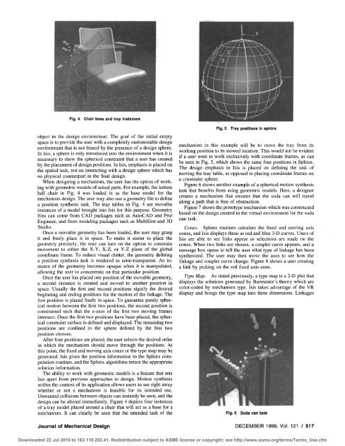
Fig. 4 Chair base and tray <strong>in</strong>stances<br />
object <strong>in</strong> the design environment. The goal of the <strong>in</strong>itial empty<br />
space is to provide the user with a completely customizable design<br />
environment that is not biased by the presence of a design sphere.<br />
In Isis, a sphere is only <strong>in</strong>troduced <strong>in</strong>to the environment when it is<br />
necessary to show the spherical constra<strong>in</strong>t that a user has created<br />
by the placement of design positions. In Isis, emphasis is placed on<br />
the spatial task, not on <strong>in</strong>teract<strong>in</strong>g with a design sphere which has<br />
no physical counterpart <strong>in</strong> the f<strong>in</strong>al design.<br />
When design<strong>in</strong>g a mechanism, the user has the option of work<strong>in</strong>g<br />
with geometric models of actual parts. For example, the lecture<br />
hall chair <strong>in</strong> Fig. 4 was loaded <strong>in</strong> as the base model for the<br />
mechanism design. The user may also use a geometry file to def<strong>in</strong>e<br />
a position synthesis task. The tray tables <strong>in</strong> Fig. 4 are movable<br />
<strong>in</strong>stances of a model brought <strong>in</strong>to Isis for this purpose. Geometry<br />
files can come from CAD packages such as AutoCAD and Pro/<br />
Eng<strong>in</strong>eer, and from model<strong>in</strong>g packages such as MultiGen and 3D<br />
Studio.<br />
Once a movable geometry has been loaded, the user may grasp<br />
it and freely place it <strong>in</strong> space. To make it easier to place the<br />
geometry precisely, the user can turn on the option to constra<strong>in</strong><br />
movement to either the X-Y, X-Z, or Y-Z plane of the global<br />
coord<strong>in</strong>ate frame. To reduce visual clutter, the geometry def<strong>in</strong><strong>in</strong>g<br />
a position synthesis task is rendered as semi-transparent. An <strong>in</strong>stance<br />
of the geometry becomes opaque when it is manipulated,<br />
allow<strong>in</strong>g the user to concentrate on that particular position.<br />
Once the user has placed one position of the movable geometry,<br />
a second <strong>in</strong>stance is created and moved to another position <strong>in</strong><br />
space. Usually the first and second positions signify the desired<br />
beg<strong>in</strong>n<strong>in</strong>g and end<strong>in</strong>g positions for the motion of the l<strong>in</strong>kage. The<br />
first position is placed freely <strong>in</strong> space. To guarantee purely spherical<br />
motion between the first two positions, the second position is<br />
constra<strong>in</strong>ed such that the z-axes of the first two mov<strong>in</strong>g frames<br />
<strong>in</strong>tersect. Once the first two positions have been placed, the spherical<br />
constra<strong>in</strong>t surface is def<strong>in</strong>ed and displayed. The rema<strong>in</strong><strong>in</strong>g two<br />
positions are conf<strong>in</strong>ed to the sphere def<strong>in</strong>ed by the first two<br />
position choices.<br />
After four positions are placed, the user selects the desired order<br />
<strong>in</strong> which the mechanism should move through the positions. At<br />
this po<strong>in</strong>t, the fixed and mov<strong>in</strong>g axis cones or the type map may be<br />
generated. Isis gives the position <strong>in</strong>formation to the Sph<strong>in</strong>x computation<br />
rout<strong>in</strong>es, and the Sph<strong>in</strong>x algorithms return the appropriate<br />
solution <strong>in</strong>formation.<br />
The ability to work with geometric models is a feature that sets<br />
Isis apart from previous approaches to design. Motion synthesis<br />
with<strong>in</strong> the context of its application allows users to see right away<br />
whether or not a mechanism is feasible for its <strong>in</strong>tended use.<br />
Unwanted collisions between objects can <strong>in</strong>stantly be seen, and the<br />
design can be altered immediately. Figure 4 depicts four <strong>in</strong>stances<br />
of a tray model placed around a chair that will act as a base for a<br />
mechanism. It can clearly be seen that the <strong>in</strong>tended task of the<br />
Journal of Mechanical Design<br />
Fig. 5 Tray positions <strong>in</strong> sph<strong>in</strong>x<br />
mechanism <strong>in</strong> this example will be to move the tray from its<br />
work<strong>in</strong>g position to its stowed location. This would not be evident<br />
if a user were to work exclusively with coord<strong>in</strong>ate frames, as can<br />
be seen <strong>in</strong> Fig. 5, which shows the same four positions <strong>in</strong> Sph<strong>in</strong>x.<br />
The design emphasis <strong>in</strong> Isis is placed on def<strong>in</strong><strong>in</strong>g the task of<br />
mov<strong>in</strong>g the tray table, as opposed to plac<strong>in</strong>g coord<strong>in</strong>ate frames on<br />
a constra<strong>in</strong>t sphere.<br />
Figure 6 shows another example of a spherical motion synthesis<br />
task that benefits from us<strong>in</strong>g geometric models. Here, a designer<br />
creates a mechanism that ensures that the soda can will travel<br />
along a path that is free of obstruction.<br />
Figure 7 shows the prototype mechanism which was constructed<br />
based on the design created <strong>in</strong> the virtual environment for the soda<br />
can task.<br />
Cones. Sph<strong>in</strong>x rout<strong>in</strong>es calculate the fixed and mov<strong>in</strong>g axis<br />
cones, and Isis displays these as red and blue 3-D curves. Users of<br />
Isis are able to see l<strong>in</strong>ks appear as selections are made on the<br />
cones. When two l<strong>in</strong>ks are chosen, a coupler curve appears, and a<br />
message box opens to tell the user what type of l<strong>in</strong>kage has been<br />
synthesized. The user may then move the axes to see how the<br />
l<strong>in</strong>kage and coupler curve change. Figure 8 shows a user creat<strong>in</strong>g<br />
a l<strong>in</strong>k by pick<strong>in</strong>g on the red fixed axis cone.<br />
Type Map. As stated previously, a type map is a 2-D plot that<br />
displays the solutions generated by Burmester's theory which are<br />
color-coded by mechanism type. Isis takes advantage of the VR<br />
display and br<strong>in</strong>gs the type map <strong>in</strong>to three dimensions. L<strong>in</strong>kages<br />
Fig. 6 Soda can tasl<<br />
DECEMBER 1999, Vol. 121 / 517<br />
Downloaded 22 Jul 2010 to 163.118.202.41. Redistribution subject to ASME license or copyright; see http://www.asme.org/terms/Terms_Use.cfm