Jean-Louis Malinge - EEWeb
Jean-Louis Malinge - EEWeb
Jean-Louis Malinge - EEWeb

Create successful ePaper yourself
Turn your PDF publications into a flip-book with our unique Google optimized e-Paper software.
TECHNICAL ARTICLE<br />
Q<br />
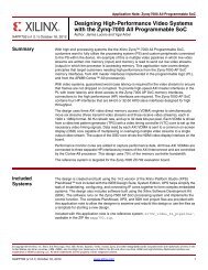
With a decrease in temperature<br />
the system dissipates less<br />
power so that the temperature<br />
rises and equilibrium is restored<br />
Figure 2: Power dissipation versus temperature<br />
also ensures that engineers give themselves adequate<br />
margins so that devices’ continued operation is ensured.<br />
Figure 2 shows power dissipation on the vertical axis and<br />
temperature on the horizontal axis. The gently sloped<br />
red line is referred to as the ‘device operating line.’ This<br />
represents a device whose power dissipation increases<br />
with temperature. The blue diagonal line describes 1/<br />
θJx as set out in equation 3. This is referred to as the<br />
‘system line.’ It describes how increases in the device’s<br />
operating temperature go with increasing amounts of<br />
power that may be successfully dissipated from that<br />
device. The intersection of these two lines gives the<br />
nominal steady-state operating point. Thus, to the right<br />
of the steady-state operating point, more power leaves<br />
the system than the device produces, so it cools; to the<br />
left, less power leaves the system than is introduced, so<br />
it heats up. Either way, the imbalance in power causes<br />
TJ to move back toward the steady-state operating point.<br />
Once this stability is lost, however, the device is at risk of<br />
thermal runaway. This will happen if the slope of the blue<br />
line is less than that of the red line<br />
In summary, the whole business of ensuring device<br />
level thermal management has become increasingly<br />
System<br />
Line<br />
As temperature rises,<br />
more heat may be dissipated<br />
Device<br />
Operating<br />
Line<br />
T X T J T<br />
difficult with the advent of more compact, powerdense,<br />
functionally-complex devices enclosed in plastic<br />
packages. Inside the package, there are multiple heat<br />
paths that need to be taken into account; the idea that the<br />
package’s thermal properties can be represented by a<br />
single number is, at best, naive. Simultaneously, outside<br />
the package, specific boundary conditions dictate<br />
how heat flow from the device takes place. Engineers<br />
need to be fully aware of the thermal issues involved if<br />
their system designs are to achieve the reliability and<br />
performance levels they require.<br />
About the Author<br />
Roger Stout received his BSE in Mechanical Engineering<br />
at ASU in 1977, and went on as a Hughes Fellow to earn his<br />
MSME at the California Institute of Technology in 1979.<br />
He then joined Motorola in the equipment engineering<br />
side of the semiconductor business, which after about<br />
four years evolved into factory automation and control<br />
engineering. In about 1990, he took on the responsibility<br />
for thermal characterization of ASIC products. Roger<br />
holds six patents, and has been a registered Professional<br />
Engineer (Mechanical) in the state of Arizona since 1983.<br />
■<br />
<strong>EEWeb</strong> | Electrical Engineering Community Visit www.eeweb.com 19<br />
TECHNICAL ARTICLE