Jean-Louis Malinge - EEWeb
Jean-Louis Malinge - EEWeb
Jean-Louis Malinge - EEWeb

Create successful ePaper yourself
Turn your PDF publications into a flip-book with our unique Google optimized e-Paper software.
<strong>EEWeb</strong><br />
PULSE<br />
<strong>EEWeb</strong>.com<br />
Issue 46<br />
May 15, 2012<br />
<strong>Jean</strong>-<strong>Louis</strong><br />
<strong>Malinge</strong><br />
Kotura<br />
Electrical Engineering Community
<strong>EEWeb</strong><br />
Electrical Engineering Community<br />
Contact Us For Advertising Opportunities<br />
1.800.574.2791<br />
advertising@eeweb.com<br />
www.eeweb.com/advertising
TABLE OF CONTENTS<br />
<strong>Jean</strong>-<strong>Louis</strong> <strong>Malinge</strong> 4<br />
KOTURA<br />
Interview with <strong>Jean</strong>-<strong>Louis</strong> <strong>Malinge</strong> - CEO and President<br />
What is Silicon Photonics? 8<br />
BY JEAN-LOUIS MALINGE<br />
The new optical communication technology that is revolutionizing the telecommunications<br />
industry.<br />
Featured Products 10<br />
From PSPICE Netlist to Allegro<br />
Design Sub-Circuit<br />
BY DON LAFONTAINE WITH INTERSIL<br />
This step-by-step procedure enables the user to take any PSPICE netlist and convert it into a<br />
sub-circuit for insertion into their Cadence Allegro simulator.<br />
Thermal Basics of Complex Devices 17<br />
BY ROGER STOUT WITH ON SEMICONDUCTOR<br />
Practical concerns and considerations for device level thermal management.<br />
12<br />
RTZ - Return to Zero Comic 20<br />
<strong>EEWeb</strong> | Electrical Engineering Community Visit www.eeweb.com 3<br />
TABLE OF CONTENTS
INTERVIEW<br />
<strong>Jean</strong>-<strong>Louis</strong><br />
<strong>Malinge</strong><br />
How did you get into<br />
electronics/engineering and<br />
when did you start?<br />
As you probably already noticed<br />
from my name, I am of French<br />
origin. I am a physicist by training<br />
and received my education in<br />
France in the 70s. When I was<br />
<strong>Jean</strong>-<strong>Louis</strong> <strong>Malinge</strong> - CEO and President<br />
Koturaas it<br />
initially searching for work, I was<br />
looking at industries or technologies<br />
that were at the very beginning of<br />
their life, and showed promise for<br />
success, which brought me to two<br />
areas. One was gallium arsenide<br />
devices because this was before<br />
the time that silicon was as available<br />
is today, and gallium arsenide<br />
was a good material system for<br />
fast electronics. The other area<br />
was optical fiber. I ended up<br />
randomly starting in optical fiber<br />
and photonics for communications<br />
and joined a company named<br />
Thompson CSF, a very large group<br />
in France. I started to work initially in<br />
the design and development of the<br />
first fiber optic communication line<br />
in France, which was in downtown<br />
Paris at the end of the 70s. I then<br />
migrated progressively to work on<br />
the design and realization of the first<br />
broadband network of what was<br />
one of the first Fiber to the Home<br />
(FTTH) demonstrations. At the<br />
end of the 1980s, I joined Corning<br />
Inc., which is a large fiber optics<br />
company headquartered in upstate<br />
New York. I started working for<br />
Corning in France, migrated to the<br />
US in the early 1990s. After that, I<br />
went through an executive MBA<br />
at Sloan School at MIT and joined<br />
the US side of Corning, working<br />
<strong>EEWeb</strong> | Electrical Engineering Community Visit www.eeweb.com 4<br />
FEATURED INTERVIEW
INTERVIEW<br />
first in development, and migrating<br />
progressively to the business side.<br />
By the end of the 1990s, I was<br />
running a large division of Corning<br />
focused on optical components.<br />
When telecom collapsed in 2001,<br />
all of the companies in telecom<br />
and photonics experienced a very<br />
sudden large revenue decrease<br />
and had to restructure their assets.<br />
In 2004 we started Kotura, where I<br />
am now, to focus on the next wave<br />
of photonics in the network using<br />
silicon as the material system<br />
of choice to design, develop<br />
and manufacture opto-electrical<br />
components.<br />
How did you initially form your<br />
company? Was it yourself and<br />
other people?<br />
Kotura is the restart of a startup that<br />
was created during the Internet<br />
bubble days in 2000. By 2003 and<br />
2004, the original company was<br />
going nowhere, so the investors<br />
decided to restart the company at<br />
which time I joined as the CEO. At<br />
that point, Kotura had no product<br />
sales, but there was a base of<br />
technology and engineers. We<br />
restarted the company during the<br />
worst period of time for photonics<br />
because it was very difficult to talk<br />
about photonics and communication<br />
in the same sentence and be able to<br />
raise any money.<br />
Can you tell us about the<br />
company—some of the<br />
products you guys have<br />
developed over time or areas<br />
of development that have<br />
gained traction?<br />
The goal of Kotura is to build optical<br />
components on the same material<br />
and using the same platform that<br />
we do to manufacture integrated<br />
circuits. Until recently, all of the<br />
photonics components that are used<br />
in telecommunication networks are<br />
based on a multitude of platforms<br />
and materials that are assembled<br />
together in modules to create a<br />
particular function, for example,<br />
an optical transmitter or an optical<br />
receiver. In a nutshell, our objective<br />
is to use the experience<br />
The goal of Kotura<br />
is to build optical<br />
components on the<br />
same material and<br />
using the same<br />
platform that we<br />
do to manufacture<br />
integrated circuits.<br />
and the learning curve of the entire<br />
IC industry in silicon and reuse<br />
the materials base to manufacture<br />
photonics components. In 2006, we<br />
started to ship products in volume<br />
completely based on this silicon<br />
photonics platform. Currently, our<br />
products are used by three of the top<br />
five telecom companies and dozens<br />
of smaller companies running live<br />
voice and Internet traffic all over<br />
the world. Our devices have logged<br />
over 1 billion hours in the network,<br />
gaining us credibility with our<br />
customers and demonstrating the<br />
quality and reliability of our products.<br />
Every few years, we are developing<br />
a new generation of those chips<br />
– some are enhancements of a<br />
previous design, but some are<br />
brand new devices that we are<br />
trying to bring to the market. We are<br />
currently working on a design that<br />
can transport 100GB of data over a<br />
single fiber for distances up to 10km<br />
while consuming less than five watts<br />
of power. These chips are quite<br />
complex; they integrate Wavelength<br />
Multiplexing and Demultiplexing on<br />
the chip, and they are much smaller<br />
than a postage stamp. They will<br />
enable high speed links between<br />
routers and servers in the data<br />
center, which is really where we are<br />
aiming our technology.<br />
Do you have a fab or are you<br />
a fabless company?<br />
We have a small fab that is doing<br />
two things for us: it provides quick<br />
turnaround on new designs, and<br />
it manufactures the products that<br />
we are sending to different OEMs.<br />
We start with bare CMOS wafers,<br />
then we fabricate all of the optoelectronic<br />
functions on them. Those<br />
wafers are diced and packaged by<br />
a contract manufacturer in Asia.<br />
Our finished products are shipped<br />
to key customers around the world.<br />
Besides the standard products<br />
that you are currently<br />
making, do you license your<br />
technology if people would<br />
like to include some of this<br />
photonic technology in an IC<br />
design they might be working<br />
on?<br />
We are engaged in discussions<br />
about licensing technology. Since<br />
we founded the company, we have<br />
created a lot of patents. Kotura<br />
currently has around 140 patents<br />
on our silicon photonic products<br />
and design. Of those, there are 70<br />
granted patents and 70 applications.<br />
<strong>EEWeb</strong> | Electrical Engineering Community Visit www.eeweb.com 5<br />
FEATURED INTERVIEW
INTERVIEW<br />
So this is an area where we are<br />
generating intellectual property and<br />
discussing with interested parties<br />
about licensing some of the things<br />
we have done. We are at a turning<br />
point in this entire photonics industry<br />
that I will try to describe. All the way<br />
back to the 90s and early 2000s, after<br />
the collapse of the Internet bubble,<br />
optical fiber communication was<br />
mostly limited to the long distance<br />
transport of information. When you<br />
want to transport data from LA to<br />
NY or LA to Paris, that transmission<br />
is completely through optical fiber.<br />
The metro area around major cities<br />
is also based upon fiber optics. But,<br />
up until a few years ago, for shorter<br />
distances when you were going<br />
a little further down in the layer of<br />
the network, everything was mostly<br />
copper with very limited optics.<br />
The industry had not yet reached<br />
the need of optics at that level<br />
because the Internet was a smaller<br />
place, speeds were slower and<br />
power consumption was not a big<br />
issue. Today, the Internet is huge<br />
and growing fast. We are currently<br />
at a period of time in which we<br />
are accumulating and storing an<br />
unbelievable amount of data. There<br />
are numbers showing that every year<br />
we are accumulating and storing as<br />
much information as we did for the<br />
entire history known to mankind on<br />
this world. This is creating a huge<br />
stress in all those data centers and<br />
all the different boxes inside the<br />
data center that we are using to<br />
create and store the data. Social<br />
networking sites like YouTube and<br />
Facebook are all adding more<br />
video, images and data to be stored<br />
and transmitted. This is creating a<br />
huge bandwidth demand; not just<br />
on the long distance networks, but<br />
also inside<br />
Our company actually<br />
looks like the Los<br />
Angeles area. We have<br />
a world class team<br />
and an extremely<br />
diverse set of people...<br />
this diversity is, I<br />
think, very important<br />
in creating the kind<br />
of technology we<br />
are developing...<br />
data centers. This demand has to<br />
be resolved by a new technology<br />
platform like silicon photonics, and<br />
we believe this will happen in the<br />
few years to come.<br />
Any particular area or<br />
application you plan to target<br />
first?<br />
What we are working very actively<br />
on right now are solutions for data<br />
centers, supercomputers and then<br />
eventually consumer electronics.<br />
We are focusing a lot of our design<br />
and development power on what we<br />
call a 100G optical engine in silicon,<br />
where essentially from this very<br />
tiny chip we can push through the<br />
fiber 100G of information. Side by<br />
side, if we multiplied that by a large<br />
number of fibers, you can reach<br />
very quickly a large bandwidth of<br />
information transmittance. What we<br />
are developing today is mostly going<br />
into telecommunication networks,<br />
data centers and supercomputers.<br />
How many people work for<br />
Kotura?<br />
We currently have 60 to 65 highly<br />
technical employees based in<br />
Monterey Park, California, just<br />
outside of Los Angeles. Those<br />
people are mostly engineers and<br />
PhDs. In fact, we have 22 PhDs.<br />
Designing and fabricating optical<br />
chips in silicon is a big task with<br />
a huge impact for our customers.<br />
Our packaging is done at a contract<br />
manufacturer in Asia. Last year,<br />
we opened an office in Shenzhen,<br />
China.<br />
How would you describe<br />
the work culture in your<br />
company?<br />
Our company actually looks like<br />
the Los Angeles area. We have a<br />
world class team and an extremely<br />
diverse set of people. The number<br />
of languages spoken here is<br />
amazing. This diversity is, I think,<br />
very important in creating the kind<br />
of technology we are developing as<br />
we are looking at doing things very<br />
differently, and we need to bring a lot<br />
of innovation and a lot of new ideas<br />
to this world. I speak of diversity<br />
of origin, but obviously we have<br />
diversity of skills and backgrounds<br />
too—those with IC backgrounds,<br />
process engineering backgrounds,<br />
optical design backgrounds. All<br />
those people are living in a close<br />
environment with each other, which<br />
is a good way to create innovation<br />
by mixing different skills and<br />
expertise close together to try to<br />
facilitate communication between<br />
those different groups of people.■<br />
<strong>EEWeb</strong> | Electrical Engineering Community Visit www.eeweb.com 6<br />
FEATURED INTERVIEW
Applications<br />
IGBT/MOSFET Gate Drive<br />
AC and Brushless<br />
DC Motor Drives<br />
Renewable Energy<br />
Inverters<br />
Industrial Inverters<br />
Switching Power Supplies<br />
Avago Technologies, an industry leader<br />
in IGBT Gate Drive technology solutions<br />
introduces our Next Generation series!<br />
Based on BCDMOS technology Avago can<br />
deliver higher peak output current, better railto-rail<br />
output voltage performance and faster<br />
speed than previous generation products.<br />
The increased drive and speed along with<br />
the very high CMR (common mode rejection)<br />
and isolation voltage will enable you to build<br />
more efficient and reliable motor drive and<br />
power conversion systems. In addition the<br />
SO6 package which is up to 50% smaller than<br />
conventional DIP packages facilitates smaller<br />
more compact design.<br />
Avago Technologies Optocoupler Solutions<br />
2 Times Faster, 50% Smaller,<br />
True Rail-to-Rail Output Voltage<br />
IGBT Gate Drives<br />
Benefits<br />
• Suitable for wide range of IGBT class for different<br />
market applications<br />
• High output peak current for fast and efficient<br />
IGBT operation<br />
• Rail-to-rail output voltage for reliable IGBT<br />
operation<br />
• Lower system power budget<br />
• Suitable for bootstrap power supply operation<br />
• Reduce dead time and improve system efficiency<br />
• Prevent erroneous driving of IGBT in noisy<br />
environment<br />
• 40%-50% smaller than DIP package for space and<br />
cost savings<br />
To request a free evaluation board go to:<br />
www.avagotech.com/optocouplers
What Is Silicon<br />
Photonics?<br />
<strong>Jean</strong>-<strong>Louis</strong> <strong>Malinge</strong> -<br />
CEO and President at Kotura<br />
Ever since the invention of the<br />
transistor more than 60 years ago,<br />
semiconductor chips have used<br />
electrons for communications.<br />
Each new generation of devices<br />
offered more transistors in a smaller<br />
area, operating at faster speeds.<br />
Today, the semiconductor industry<br />
exceeds $250B per year with a<br />
single CMOS chip containing as<br />
many as a billion or more transistors.<br />
These complex circuits are still 100<br />
percent electrical.<br />
Meanwhile, during the 1980s,<br />
optical communications based<br />
on lasers and optical fiber was<br />
introduced for long distance<br />
telecommunication. Instead of lowcost<br />
silicon, optical communication<br />
required exotic material systems for<br />
lasers, detectors, filters, isolators,<br />
modulators, and switches. Optical<br />
transceivers were hand assembled<br />
from hundreds of piece parts and,<br />
in many cases, still are today. Even<br />
though it was expensive, optical<br />
communication had the advantage<br />
of being able to transmit huge<br />
amounts of data over long distances.<br />
The Internet was built using the<br />
back bone of telecommunications<br />
optical networks.<br />
Silicon photonics brings<br />
optical communication into the<br />
semiconductor industry, enabling<br />
a whole new range of applications.<br />
Opto-electronic functions are<br />
fabricated on the same CMOS<br />
wafers using the same equipment<br />
and methods as electronic chips.<br />
The wafers are processed in<br />
the same fabs as those running<br />
electronics chips. The wafers are<br />
diced into chips just like electrical<br />
ones. Optical chips can be just<br />
as inexpensive as their electrical<br />
cousins. When mass volumes are<br />
needed, the wafer fab simply runs<br />
more wafers of the same recipe.<br />
Silicon photonics eliminates<br />
the need for hand assembly of<br />
hundreds of parts. Silicon photonics<br />
chips are much, much smaller than<br />
the optical subassemblies they<br />
replace. A silicon photonics chip<br />
can support 100 gigabits per second<br />
transmission on a chip less than half<br />
<strong>EEWeb</strong> | Electrical Engineering Community Visit www.eeweb.com 8
PROJECT<br />
the size of a postage stamp, which<br />
enables faster communications<br />
between the high speed CPU<br />
chips in supercomputers and the<br />
memory or other CPUs. This new<br />
technology allows high speed<br />
routers and switches in data centers<br />
to communicate with pipes of 100<br />
Gb/s instead of 10 Gb/s. These<br />
chips can enable the backplanes in<br />
high performance computers to run<br />
at 100 Gb/s, 400 Gb/s or even one<br />
terabit per second.<br />
Previously, optical solutions<br />
assembled from discrete<br />
components had to be packaged<br />
in expensive, hermetically sealed<br />
packages. A speck of dust between<br />
any of the components would<br />
inhibit the light path and render the<br />
product useless. By contrast, silicon<br />
photonics devices are totally selfcontained<br />
within the layers of the<br />
chip. With no need for hermiticity,<br />
they can reuse low-cost industry<br />
standard electronics packaging.<br />
Another huge advantage of optical<br />
communication is Wave Division<br />
Multiplexing (WDM). With WDM,<br />
four, eight or even 40 channels of<br />
light, each at a different frequency,<br />
can operate in parallel over a single<br />
strand of optical fiber. Fiber is<br />
cheap, especially when a single<br />
strand is replacing so many copper<br />
cables. On the computer board<br />
itself, optical buses consume far<br />
less space than electrical buses,<br />
allowing more space for CPUs,<br />
memory and switching chips. For<br />
large pipes, optical interconnect<br />
is far less expensive than copper<br />
cabling.<br />
We are in the early stage phases of<br />
silicon photonics. The capability to<br />
bring faster, smaller interconnects,<br />
which consume less power, offers<br />
the entire semiconductor industry<br />
a whole new world of opportunities.<br />
Next generation data centers,<br />
high performance computers<br />
and eventually consumer video<br />
products will all benefit from optical<br />
interconnects built from silicon<br />
photonics. ■<br />
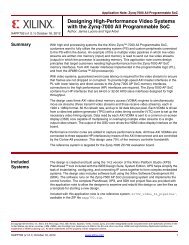
Figure 1: Kotura’s optical engine is just two tiny silicon photonics chips that can transmit data at speeds of 100 Gb/s and more. Wafer scale<br />
integration eliminates hundreds of piece parts and cost effectively scales to millions of units.<br />
<strong>EEWeb</strong> | Electrical Engineering Community Visit www.eeweb.com 9<br />
FEATURED PROJECT
FEATURED PRODUCTS<br />
Low Power 5MBd Digital Optocouplers<br />
Avago Technologies, a leading supplier of analog interface<br />
components for communications, industrial and consumer applications,<br />
announcedthe ACPL-M21L/021L/024L/W21L/K24Loptocouplerfamily.<br />
These optocouplers consume less power as compared to other similar<br />
5MBd optocouplers in the market. The ACPL-x2xLoptocouplers are<br />
designed to meet customer needs for lower power, higher isolation<br />
voltage, and better common-mode rejection (CMR) performance, thanks<br />
to the excellent performance of the new LED and detector IC design.<br />
Avago Technologies’ digital optocouplers are used in a wide variety of<br />
isolation applications ranging from power supply and motor control circuits to data communications and digital<br />
logic interface circuits. All newoptocouplers are compliant to industrial safety standards such asIEC/EN/DIN EN<br />
60747-5-5 approval for reinforced insulation, UL 1577 and CSA. The first available optocoupler, the ACPL-M21L is<br />
immediately available in sample quantities, and will sell for $0.88 apiece in lots of 10k units. For more information,<br />
please click here.<br />
Broadband RF Mixer<br />
Linear Technology announces the LTC5567, a 300MHz to 4GHz<br />
downconverting mixer with outstanding IIP3 (Input Third Order<br />
Intercept) of 26.9dBm, low power consumption of 294mW, and wide IF<br />
bandwidth of 2.5GHz to support 4G wireless base stations and a wide<br />
range of high dynamic range receiver applications. The LTC5567’s<br />
wide 300MHz to 4GHz operating frequency range provides versatility<br />
in a single device, enabling operation in any of the cellular bands from<br />
700MHz to 2.7GHz. The mixer features a conversion gain of 1.9dB and<br />
a noise figure of 11.8dB, providing excellent dynamic range for a wide variety of receiver applications. Additionally,<br />
the LTC5567’s IF output has a wide frequency range of 5MHz to 2500MHz, supporting wideband applications such<br />
as cable TV downlink transmitters and digital predistortion (DPD) receivers. Moreover, the LTC5567’s RF input is<br />
designed to withstand strong in-band blocking signals, while delivering a best-in-class noise figure of 16.5dB with<br />
a +5dBm blocker, ensuring enhanced receiver sensitivity in the presence of interference. For more information,<br />
please click here.<br />
Contsant Power LED Controller<br />
Texas Instruments Incorporated introduced a new LED controller with<br />
constant power regulation. The LM3447 AC/DC LED driver includes a<br />
dimmer detect, phase decoder and adjustable hold current circuits to<br />
provide smooth and flicker-free dimming operation in off-line, isolated<br />
LED lighting applications, including A19, E26/27 and PAR30/38 bulbs,<br />
as well as can light retrofits. raditional drivers use constant current<br />
control to accurately regulate LED forward current. This approach<br />
produces consistent light output or intensity from LEDs in the same<br />
bin. However, once current is applied to the LED, its solder point<br />
temperature rises, leading to a decrease in forward voltage and a<br />
drop in efficacy. Conversely, by using the new LM3447 with constant power regulation, the LED forward voltage<br />
droop over temperature is offset by an increase in LED current to maintain constant LED power. The result is up<br />
to 10-percent improvement in efficacy across the expected operating temperature range of the fixture. For more<br />
information, please click here.<br />
<strong>EEWeb</strong> | Electrical Engineering Community Visit www.eeweb.com 10<br />
FEATURED PRODUCTS
From<br />
PSPICE<br />
Netlist<br />
to<br />
Allegro<br />
Design<br />
Sub-<br />
Circuit<br />
Here is a common everyday<br />
scenario in the electronics industry:<br />
Designers who’ve found a good<br />
op-amp for their project want to<br />
run simulations on their design<br />
before they head into the lab to<br />
build up a prototype. They note that<br />
the device manufacturer offers a<br />
PSPICE model netlist in their data<br />
sheet, but remain unsure how to<br />
convert the PSPICE model netlist<br />
into a sub-circuit for the simulator. If<br />
the simulator is a Cadence Allegro<br />
simulator, then there is a step-bystep<br />
process to convert the data<br />
sheet netlist into a sub-circuit for<br />
simulations.<br />
Intersil provides a PSPICE model<br />
for all their low-speed and low<br />
power precision amps at the end<br />
of data sheets. The PSPICE model<br />
netlist and netlist schematics are<br />
included in the data sheet, along<br />
with simulation vs. characterization<br />
curves to highlight the accuracy of<br />
the PSPICE models. (To find out<br />
more details about the making of<br />
these PSPICE models, reference<br />
application note AN1556.)<br />
Copying the PSPICE Netlist<br />
Download the data sheet or the<br />
PSPICE netlist from the web. The<br />
data sheet or netlist will be in .pdf<br />
format. Open the .pdf document<br />
and right-click to enable the select<br />
tool, if it is not already selected. This<br />
Don LaFontaine<br />
Senior Application Engineer<br />
<strong>EEWeb</strong> | Electrical Engineering Community Visit www.eeweb.com 12
TECHNICAL ARTICLE<br />
will enable you to then copy and<br />
paste the entire netlist into Notepad.<br />
Name the file with the extension<br />
.MOD (not case sensitive). This file<br />
needs to be saved in a common<br />
directory with all the other files for<br />
this design.<br />
Model Editor<br />
Open the Cadence model editor<br />
(Cadence SPB16.2\AMS Simulator\<br />
Simulation Accessories\Model<br />
Editor). (Note: The version of<br />
Cadence software used in this<br />
example is SPB16.2.) The look<br />
and feel may change with different<br />
revisions of the Cadence software,<br />
but the procedure will be the same.<br />
After selecting the Model Editor, the<br />
Select Design Entry Tool screen<br />
will appear. Choose the Default<br />
Design Entry tool “Capture” by<br />
clicking the radial button to the<br />
left of the word “Capture,” if the<br />
default has not already selected it,<br />
and click “DONE.” Click on “File”<br />
in the tool bar and select “New.”<br />
Click on “Model” in the tool bar and<br />
select “Import.” Then browse to the<br />
folder where you put the (your file<br />
name).MOD. Select the .MOD file<br />
and click “Open.” This will load the<br />
Figure 1: Replace Generic Symbol<br />
netlist into the Model editor tool.<br />
Click on “File” in the tool bar and<br />
select “Save As.”<br />
Then, type the part name as the<br />
file name to keep track of the<br />
project and click “Save.” The file<br />
with the complete netlist is now<br />
saved as a .lib library file. Click<br />
on “File” in the tool bar and select<br />
“Export to Capture Part Library.”<br />
The Input Model Library path and<br />
the Output Part Library path will<br />
automatically be loaded. Verify that<br />
the file’s pathnames are the same<br />
with the only difference being the<br />
.lib and .olb extensions. Click “OK”<br />
and verify no “Error” messages or<br />
“Warning” messages occurred at<br />
the bottom of the screen (STATUS:<br />
0 Errors messages, 0 Warning<br />
messages). Click on “File” in the<br />
tool bar and select Model Import<br />
Wizard [Capture]. Like before, both<br />
pathnames will load automatically<br />
and should have the same file<br />
paths with the only difference being<br />
the .lib and .olb extensions. Click<br />
“Next” and the screen shown in<br />
Figure 1 will appear.<br />
This is the screen in which we will<br />
associate the pins of our PSPICE<br />
model to the pins of the sub-circuit<br />
model. The symbol shown is a<br />
generic 5 pin device. We want our<br />
Op-amp symbol to look like an<br />
Op-amp. To do this, click on the<br />
Replace Symbol button and select<br />
from the list of symbols provided<br />
with the Cadence program. This list<br />
is located at the following location<br />
on your C drive (C:\Cadence\<br />
SPB.16.2\tools\capture\libary\<br />
OPAmp.olb).<br />
If the location of your Cadence<br />
software was loaded in a different<br />
location, then search for “Cadence\<br />
SPB.”<br />
When selecting your symbol, all<br />
that matters is the pin count. The<br />
numbers assigned to the symbol<br />
pins can be changed later. Just<br />
scroll through the list to find a<br />
symbol that matches a desired<br />
pinout and pin count of your device.<br />
In this example, we selected the<br />
TLC2201. Click “Next.” Then click<br />
on the row under the Symbol Pin<br />
column to activate pull down menu<br />
box under the symbol column. Now<br />
pick the associated pin to match<br />
the Model Terminal function in the<br />
Model Terminal column. Repeat for<br />
all Model Terminal pins as shown in<br />
Figure 2.<br />
Click “Save Symbol” then finish<br />
and verify no “Error” messages or<br />
“Warning” messages (STATUS:<br />
0 Errors messages, 0 Warning<br />
messages). Click “OK” and then<br />
close the Model Editor. You have<br />
now created the sub-circuit to<br />
import into your simulator.<br />
Using the New Sub-circuit<br />
to Run Simulations<br />
Open the Cadence Software<br />
<strong>EEWeb</strong> | Electrical Engineering Community Visit www.eeweb.com 13<br />
TECHNICAL ARTICLE
TECHNICAL ARTICLE<br />
Figure 2: All Pins Associated to Symbol<br />
Figure 3: Configuration File to Add Library<br />
(Cadence SPB 16.2\Design Entry<br />
CSI). From the Cadence Product<br />
Choices screen, Select “Allegro<br />
Design Entry CIS” and click “OK.”<br />
Click on “File” in the tool bar and<br />
select “New,” and then “Project.”<br />
Type in the name of the project and<br />
click on the radial button to the left<br />
of Analog of Mixed A/D. Browse to<br />
where you saved the Netlist in the<br />
common directory (you must have<br />
all the files located in the same<br />
directory) and click “OK.”<br />
The user can select to base their<br />
new project on an existing project<br />
or start a new one. Selecting to base<br />
upon an existing project will carry<br />
over the existing project with all the<br />
simulation profiles and schematics.<br />
This can be a real time saver if the<br />
new project is very similar to an old<br />
project. In this example, we will<br />
choose to create a new project.<br />
Click “OK.” Click on .\(your<br />
file name) .dsn and then the<br />
SCHEMATIC1 to open the PAGE1<br />
tab and then click on the PAGE1<br />
tab. This is where the new subcircuit<br />
will be placed to run the<br />
simulations. Before we can place<br />
the new sub-circuit model and run<br />
a simulation, we need to set-up<br />
the simulation profile and add the<br />
library. Click on PSPICE in the tool<br />
bar and select “New Simulation<br />
Profile.” Then, type in any name<br />
that will help you keep track of<br />
the different simulations and click<br />
“Create.” Click the “Configuration<br />
Files” tab at the top. Then click on<br />
“Library” in the Category field on<br />
the left hand side. Browse to where<br />
you saved the Library file (.lib).<br />
Then click the “Add to Design”<br />
button. The Simulation Settings<br />
screen should look like that shown<br />
in Figure 3 with the file path name<br />
being the location of the common<br />
directory.<br />
Click the “Apply” button.<br />
Now click the analysis tab (Figure<br />
3) and configure the simulation for<br />
the simulation conditions desired.<br />
In this example, we will setup the<br />
simulation as follows: Analysis Type<br />
= AC Sweep/Noise, Options =<br />
General Settings, Start frequency =<br />
0.1Hz, End Frequency = 100Meg<br />
Hz, Points/Decade = 100.<br />
The analysis selected for this<br />
example is an AC Sweep/Noise.<br />
Other types of analysis are: Time<br />
Domain (Transient), DC Sweep and<br />
Bias Point. Just click the down arrow<br />
in the analysis type section to access<br />
the different Analysis options. When<br />
<strong>EEWeb</strong> | Electrical Engineering Community Visit www.eeweb.com 14<br />
TECHNICAL ARTICLE
TECHNICAL ARTICLE<br />
Figure 4: Part Placement Tool<br />
finished, click “OK.”<br />
The user will need to add the<br />
Library .olb to the simulator. To do<br />
this, click on “Place” in the tool bar<br />
and select “Part.” This will bring<br />
up the part placement tool at the<br />
far right of the simulator as shown<br />
in Figure 4. To add the library,<br />
click on the tab where the arrow is<br />
pointing to in Figure 4. Browse to<br />
where you saved the Netlist in the<br />
common directory, select the .olb<br />
file and click “Open.” The new .olb<br />
file has been added to the library list<br />
(highlighted in blue Figure 4) Now<br />
you are ready to add the sub-circuit<br />
to your simulation schematic and<br />
start your simulations.<br />
Adding the Sub-circuit to<br />
Your Simulation Schematic<br />
With the .lib file added to the<br />
simulation profile and the .olb<br />
file added to the part placement<br />
tool, you are now ready to place<br />
the Op-amp sub-circuit into your<br />
simulation schematic. Figure 4<br />
shows the part placement tool after<br />
the .olb has been added to it. Under<br />
the Libraries section of Figure 4,<br />
find the new .olb symbol you added<br />
in the previous step (highlighted<br />
in blue). Double-click on the file to<br />
add the sub-circuit to the “Part” list<br />
section (also highlighted in blue).<br />
<strong>EEWeb</strong><br />
Electrical Engineering Community<br />
Join Today<br />
www.eeweb.com/register<br />
Double click on the “Part” in the part<br />
list section and add the sub-circuit<br />
to the simulation schematic. You are<br />
now able to configure the Op-amp<br />
for simulations.<br />
This step-by-step procedure<br />
enables the user to take any<br />
PSPICE netlist and convert it into<br />
a sub-circuit for insertion into their<br />
Cadence Allegro simulator. The<br />
straightforward PSPICE models<br />
offered by Intersil (reference<br />
AN1556) make it easy for the user<br />
to edit the netlist and run worst-case<br />
simulations for some of the Op-amp<br />
parameters.<br />
About the Author<br />
Don LaFontaine is a Sr. Principal<br />
Application Engineer/Sr. Engineering<br />
Manager with Intersil’s Signal<br />
Path product line in Palm Bay, Florida.<br />
His focus is on precision analog<br />
products. He has been with Intersil<br />
Corp. for the last 30 years. He graduated<br />
from the University of South<br />
Florida with a BSEE in 1985. ■<br />
<strong>EEWeb</strong> | Electrical Engineering Community Visit www.eeweb.com 15<br />
TECHNICAL ARTICLE
<strong>EEWeb</strong><br />
Electrical Engineering Community<br />
Contact Us For Advertising Opportunities<br />
1.800.574.2791<br />
advertising@eeweb.com<br />
www.eeweb.com/advertising
TECHNICAL Roger Stout ARTICLE<br />
Back in the days when most electronics components<br />
were packaged in metal cans (or manufactured as axial<br />
leaded devices with equipment housings generally<br />
spacious and un-crowded), matters of device level<br />
thermal management were relatively straightforward<br />
for design engineers. Sadly, thermal management has<br />
become much more of a challenge nowadays – both to<br />
understand and to tackle; with multi-pin plastic packaged<br />
devices in ever-shrinking formats being incorporated<br />
into high component density portable electronics with<br />
considerable pressure being placed on available space<br />
and overall power efficiency.<br />
The following article details some of the key areas of<br />
concern in regard to device level thermal management<br />
in modern electronic products, with explanations of the<br />
fundamental theory behind it as well as some practical<br />
considerations.<br />
First principles<br />
Senior Research Scientist<br />
Thermal<br />
Basics of<br />
Complex<br />
Devices<br />
As we all know from basic thermodynamics, heat energy<br />
will flow from a higher temperature region to a lower<br />
temperature region (this being done through either<br />
conduction, convection, radiation or often a combination<br />
of these). Furthermore, the bigger the temperature<br />
difference witnessed, the greater the flow of heat will be.<br />
Historically, for discrete devices, the ‘junction’ referred to<br />
in the term junction temperature (TJ) was the PN junction<br />
of the device. Though this is true for basic rectifiers,<br />
bipolar transistors, etc, the junction now generally refers<br />
to the hottest point within the device. As we move towards<br />
more complex device constructions where different<br />
parts of the silicon have different functions at different<br />
times, locating the precise position of this point can be<br />
very difficult.<br />
A common misconception often held by engineers is that<br />
a device’s thermal resistance is an intrinsic property of<br />
the package in which it is enclosed. Among the reasons<br />
why this does not hold true is the fact that there is no<br />
isothermal surface, making it impossible to define a<br />
‘case’ temperature. Though the metal can devices of the<br />
past had a relatively good approximation of an isothermal<br />
surface, modern plastic packages tend to exhibit quite<br />
large gradients. Furthermore, in modern package types<br />
<strong>EEWeb</strong> | Electrical Engineering Community Visit www.eeweb.com 17<br />
TECHNICAL ARTICLE
TECHNICAL ARTICLE<br />
Figure 1: Difficulties in defining thermal characteristics of modern<br />
device packages – due to gradients across package surface plus<br />
leads being at different temperatures<br />
different leads will be at different temperatures, with<br />
multiple, parallel thermal paths leaving the package.<br />
Probably the most common thermal parameter cited on<br />
a device’s datasheet is θJA. Unfortunately, when it comes<br />
to designing a device for a system to locate its TJ, this<br />
figure can often be misleading.<br />
Many people unwisely think of θJA simply as the ratio of<br />
junction temperature rise above the ambient level to the<br />
power dissipated in the device. This suggests that as long<br />
as the ambient temperature for the application is known,<br />
it is possible to figure out how much power the device<br />
is going to dissipate in any specific scenario. From this,<br />
engineers assume they will be able to estimate the actual<br />
junction temperature of their device and come up with<br />
an upper limit for TJ, so they have a reasonable design<br />
margin to work with. Sometimes, device manufacturers<br />
will provide relatively thorough footnotes describing<br />
the test conditions under which the reported θJA was<br />
measured.<br />
The simple truth is that θJA is not a measure of the<br />
device’s ability to dissipate heat on its own, but, in<br />
fact, is a measure of the entire system, including the<br />
device. In many applications, the device actually has<br />
the smallest direct contribution to its θJA value of all<br />
the system variables. Factors that prove to have a more<br />
profound effect are: area, air flow, board area/thickness,<br />
the number/density of power/ground planes, PCB<br />
thickness, proximity/density other devices, etc. What<br />
device manufacturers cannot inform engineers about on<br />
the datasheets is the influence on θJA of the other heat<br />
sources within the overall thermal system.<br />
Avoiding thermal runaway<br />
Thermal runaway takes place if a semiconductor device<br />
reaches a point where it effectively has too much heat<br />
to sufficiently dissipate. The device’s temperature<br />
rises as a result and, as it is a function of temperature,<br />
further impinges on the device’s ability to dissipate heat.<br />
Effectively, the device enters a condition, through an<br />
increase in its TJ, which changes its characteristics so<br />
that it is no longer possible to attain a nominally steadystate<br />
operating point. From there, the whole thing can<br />
rapidly snowball, with the device burning out. However,<br />
what is rarely recognized is the fact that this phenomenon<br />
can be initiated well below the maximum TJ value stated<br />
on the device’s datasheet.<br />
If the thermal system around a given device has a steadystate<br />
thermal resistance, then it is possible to describe<br />
this steady-state condition using the following equation:<br />
With:<br />
TJ = Q:iJx + Tx () 1<br />
T J representing the junction temperature (in °C)<br />
Q representing the device’s power dissipation (in W)<br />
θJx representing the system’s steady state thermal<br />
resistance (in °C/W)<br />
Tx representing the thermal ground for runaway based<br />
on θJx (in °C).<br />
Examining equation 1, it is clear that a slight alteration in<br />
power will result in a small change in the TJ level. If the<br />
power level briefly rises above the equilibrium value but<br />
then returns, TJ will also return to its equilibrium. From<br />
this equation, the following relationships can be derived:<br />
Q = (TJ-Tx)/ iJx<br />
(2)<br />
(dQ/dT) is the rate of change of system power dissipation<br />
with respect to changes in junction temperature.<br />
Equations 2 or 3 show that for a small increase in TJ,<br />
the system can dissipate slightly more power than the<br />
original Q. Utilization of mathematical models allows<br />
the true nature of thermal runaway to be understood. It<br />
<strong>EEWeb</strong> | Electrical Engineering Community Visit www.eeweb.com 18<br />
TECHNICAL ARTICLE
TECHNICAL ARTICLE<br />
Q<br />
With a decrease in temperature<br />
the system dissipates less<br />
power so that the temperature<br />
rises and equilibrium is restored<br />
Figure 2: Power dissipation versus temperature<br />
also ensures that engineers give themselves adequate<br />
margins so that devices’ continued operation is ensured.<br />
Figure 2 shows power dissipation on the vertical axis and<br />
temperature on the horizontal axis. The gently sloped<br />
red line is referred to as the ‘device operating line.’ This<br />
represents a device whose power dissipation increases<br />
with temperature. The blue diagonal line describes 1/<br />
θJx as set out in equation 3. This is referred to as the<br />
‘system line.’ It describes how increases in the device’s<br />
operating temperature go with increasing amounts of<br />
power that may be successfully dissipated from that<br />
device. The intersection of these two lines gives the<br />
nominal steady-state operating point. Thus, to the right<br />
of the steady-state operating point, more power leaves<br />
the system than the device produces, so it cools; to the<br />
left, less power leaves the system than is introduced, so<br />
it heats up. Either way, the imbalance in power causes<br />
TJ to move back toward the steady-state operating point.<br />
Once this stability is lost, however, the device is at risk of<br />
thermal runaway. This will happen if the slope of the blue<br />
line is less than that of the red line<br />
In summary, the whole business of ensuring device<br />
level thermal management has become increasingly<br />
System<br />
Line<br />
As temperature rises,<br />
more heat may be dissipated<br />
Device<br />
Operating<br />
Line<br />
T X T J T<br />
difficult with the advent of more compact, powerdense,<br />
functionally-complex devices enclosed in plastic<br />
packages. Inside the package, there are multiple heat<br />
paths that need to be taken into account; the idea that the<br />
package’s thermal properties can be represented by a<br />
single number is, at best, naive. Simultaneously, outside<br />
the package, specific boundary conditions dictate<br />
how heat flow from the device takes place. Engineers<br />
need to be fully aware of the thermal issues involved if<br />
their system designs are to achieve the reliability and<br />
performance levels they require.<br />
About the Author<br />
Roger Stout received his BSE in Mechanical Engineering<br />
at ASU in 1977, and went on as a Hughes Fellow to earn his<br />
MSME at the California Institute of Technology in 1979.<br />
He then joined Motorola in the equipment engineering<br />
side of the semiconductor business, which after about<br />
four years evolved into factory automation and control<br />
engineering. In about 1990, he took on the responsibility<br />
for thermal characterization of ASIC products. Roger<br />
holds six patents, and has been a registered Professional<br />
Engineer (Mechanical) in the state of Arizona since 1983.<br />
■<br />
<strong>EEWeb</strong> | Electrical Engineering Community Visit www.eeweb.com 19<br />
TECHNICAL ARTICLE
RETURN TO ZERO<br />
<strong>EEWeb</strong> | Electrical Engineering Community Visit www.eeweb.com 20<br />
RETURN TO ZERO
RETURN TO ZERO<br />
<strong>EEWeb</strong> | Electrical Engineering Community Visit www.eeweb.com 21<br />
RETURN TO ZERO