ee pulse - EEWeb
ee pulse - EEWeb
ee pulse - EEWeb

Create successful ePaper yourself
Turn your PDF publications into a flip-book with our unique Google optimized e-Paper software.
TECHNICAL ARTICLE<br />
Set<br />
H<br />
Reset<br />
H<br />
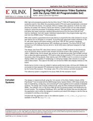
Figure 1: SR FLIP-FLOP<br />
power up and try to work out their output state. This<br />
becomes more complex as the outputs are fed back to<br />
the inputs. This means that the output is affecting the<br />
input, hence the decision making and hence the output<br />
itself. Confused? Well thats how the gate f<strong>ee</strong>ls. However<br />
after a few microseconds the gate settles and a stable<br />
state persists.<br />
S R Q<br />
0 0 !<br />
0 1 1<br />
1 0 0<br />
1 1 X<br />
Figure 2: SR TRUTH TABLE<br />
Q<br />
L<br />
Q<br />
H<br />
The truth table for the SR flip-flop is therefore as follows:<br />
The most interesting states are the Set and Reset states<br />
and the Do Nothing state—so remember these for later.<br />
The next thing to add is our clock input, which is done by<br />
adding two more NAND gates to the front end of our SR<br />
circuit. This becomes a gated SR flip-flop. The Set and<br />
Reset still work as before, but as the name suggests, it’s<br />
gated so the output only happens at certain times, when<br />
the clock input is high. This is all very good, however,<br />
it’s possible for the circuit to change its output multiple<br />
times during a clock high, which is not what we want at<br />
all. It’s also not a D-type yet. However, this is easy to fix<br />
by adding a NOT gate betw<strong>ee</strong>n the S and R inputs and<br />
renaming the S input as D (Figure 3).<br />
Our new D-Type works just like the SR flip-flop as it’s<br />
possible to change the output while the clock is high<br />
multiple times during that period. We n<strong>ee</strong>d a circuit that<br />
only latches in the D signal when the clock edge is rising.<br />
To simplify this to begin with, let’s think about the ability<br />
to generate race conditions—or in this case, a glitch.<br />
If there was only a way to make the clock <strong>pulse</strong> really<br />
really small on the positive duration, then there would<br />
not be enough time to switch back (Figure 4).<br />
L<br />
Figure 3: D-TYPE FLIP-FLOP<br />
Figure 4: GLITCH CIRCUIT<br />
This circuit uses the idea that it takes time for the gates to<br />
switch. Let’s assume for a moment that the input is LOW.<br />
One side of the AND gate is set to LOW as per the input<br />
and the other is logic HIGH because the NOT gate has<br />
inverted the input. In a perfect world, if the input changes,<br />
the NOT gate would change instantaneously and this<br />
input to the AND gate would swap and the output remain<br />
unaffected. However, because it takes time for the NOT<br />
gate to react and drive the output, there is, in fact, a small<br />
moment in time were both the inputs to the AND gate are<br />
HIGH. This sets off the chain reaction in the gate that will<br />
<strong>EEWeb</strong> | Electrical Engin<strong>ee</strong>ring Community Visit www.<strong>ee</strong>web.com 13<br />
H<br />
D<br />
CLK<br />
Q<br />
L<br />
L<br />
TECHNICAL ARTICLE