ee pulse - EEWeb
ee pulse - EEWeb
ee pulse - EEWeb

Create successful ePaper yourself
Turn your PDF publications into a flip-book with our unique Google optimized e-Paper software.
TECHNICAL ARTICLE<br />
CLK<br />
H<br />
D<br />
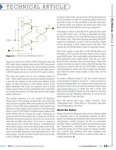
Figure 5: D_TYPE EDGE TRIGGERED CIRCUIT<br />
drive the output from LOW to HIGH. Moments later, the<br />
NOT gate output changes state and the AND gate reacts<br />
to the new stimulus. However, the chain reaction is still in<br />
place and what we s<strong>ee</strong> at the output or the AND gate is<br />
a HIGH equal to the time it took the NOT gate to switch.<br />
This may look great, but it’s not a defined period of<br />
time—other gates may not even react quickly enough to<br />
it and we are relying on the analog side effects of the<br />
gates. So what we n<strong>ee</strong>d is a nice stable version of the<br />
glitch generator. We could, for example, have a much<br />
higher sp<strong>ee</strong>d clock running somewhere that could help<br />
us process the signals, but then that would n<strong>ee</strong>d higher<br />
sp<strong>ee</strong>d clocks too…<br />
The answer, however, is in our original SR flip-flops.<br />
These react to the change of input only once when the<br />
input change is applied. With both inputs at LOW, a HIGH<br />
signal on one of the inputs generates a fast reaction and<br />
latches in a new output if one is required. The interesting<br />
effect is the DO NOTHING condition where setting both<br />
inputs HIGH will not change the output. Changing an<br />
input as LOW will then either Set or Reset the SR latch.<br />
However, driving the signal up and down as much as we<br />
want will not affect the output. If we were to connect a<br />
clock input to this circuit, then Setting or Resetting the<br />
latch would happen only on the falling edge of the clock.<br />
We are now getting close, but still not quite there. We<br />
have a circuit that responds to the edge of the clock—the<br />
wrong edge—but we can only connect this circuit so that<br />
it Sets or Resets. We n<strong>ee</strong>d both.<br />
Q<br />
H<br />
In order to have both, you n<strong>ee</strong>d two SR flip-flops that act<br />
as Set and Reset circuits. By connecting these circuits in<br />
opposite modes, it’s then possible to use the data input<br />
to decide which one latches and holds and which one<br />
flips back and forth with the clock input (Figure 5).<br />
First thing to notice is that the NOT gate that was used<br />
on the SR to turn it into a D-Type is simplified by using<br />
the NOT Q output on one of the SR flip-flops (in this case<br />
the bottom one). This lower flip-flop generates this NOT<br />
signal as a f<strong>ee</strong>dback or input to the top flip-flop, which<br />
in turn generates a NOT signal back to the first. This<br />
causes the two SR flip-flops to latch in opposite modes.<br />
The clock signal is also fed to both SR flip-flops and<br />
because of this the lower flip-flop n<strong>ee</strong>d to have a thr<strong>ee</strong><br />
input NAND gate. The overall effect is that these two flipflops<br />
generate a very useful signal. One will, as I said,<br />
latch and the other flip with the clock input. These two<br />
signals can then be used to drive a third SR flip-flop that<br />
functions as before with the DO NOTHING condition,<br />
only changing its output once the D-signal has changed<br />
and when the clock edge is s<strong>ee</strong>n, in this case, on the<br />
rising edge.<br />
It’s quite a difficult circuit to put into words because<br />
of the number of states it can be in. I could post lots of<br />
pictures showing them, but nothing works better than an<br />
animation. If you have not s<strong>ee</strong>n this website before, then<br />
http://www.falstad.com is great and has a really nice<br />
little circuit simulator. Follow the link below to load the<br />
simulator and the following instruction to bring up the<br />
edge-triggered D-type flip-flop.<br />
From the menus click here, select “Circuits,” then<br />
“Sequential Logic.” Then click on “Flip-Flops” and then<br />
“Edge-Triggered D Flip-Flop.”<br />
About the Author<br />
Digital Electronics Engin<strong>ee</strong>r with strong software skills<br />
in assembly and C for embedded systems. At ebmpapst<br />
I’m developing embedded electronics for thermal<br />
management control solutions for the air movement<br />
industry. These controllers monitor environmental inputs<br />
like Temperature, Humidity and Pressure and then<br />
control the sp<strong>ee</strong>d of our fans based on various profiles.<br />
Our controls also interface with other systems over<br />
RS232/485 or TCP/IP as well as a host of other user or<br />
control interfaces. ■<br />
<strong>EEWeb</strong> | Electrical Engin<strong>ee</strong>ring Community Visit www.<strong>ee</strong>web.com 14<br />
TECHNICAL ARTICLE