L. Ljunge - ESA
L. Ljunge - ESA
L. Ljunge - ESA

Create successful ePaper yourself
Turn your PDF publications into a flip-book with our unique Google optimized e-Paper software.
ABSTRACT<br />
GUIDANCE, NAVIGATION & CONTROL SYSTEMS.<br />
REVIEW, ANALYSIS AND FUTURE DESIGNS<br />
Lars <strong>Ljunge</strong><br />
Project Manager, RUAG Aerospace Sweden, SE-581 88 LINKÖPING, SWEDEN,, lars.ljunge@ruag.com<br />
Systems for guidance, navigation and control (GNC) of<br />
sounding rockets have long been produced by RUAG<br />
Aerospace Sweden AB, with the inaugural flight of a<br />
prototype S19 boost control system successfully<br />
performed on 10 Jan, 1976. The main objectives of the<br />
GNC systems are to reduce the impact dispersion of the<br />
re-entering vehicle, and to make it possible to launch<br />
under most all wind conditions, thereby reducing launch<br />
campaign costs.<br />
This paper first describes the various GNC generations<br />
and discusses the reasons for each development, as well<br />
as the performance of the systems in relation to the<br />
requirements laid down by the user. Finally, a look into<br />
the future is made in order to identify possible bases for<br />
next generation system solutions, and the user benefits<br />
implied by such solutions.<br />
1. THE BEGINNING<br />
Almost fifty years ago, the advantages of using<br />
sounding rockets as a research tool started to become<br />
obvious. Using military surplus motors kept the cost<br />
low, as did the philosophy: “Let knowledgeable people<br />
get the job done without a lot of regulations.” This<br />
provided short and efficient research programs, with<br />
valuable feedback of scientific results to the users.<br />
The good economy of sounding rocket based research<br />
made the scientific community ask for launches of ever<br />
heavier experiments to ever higher apogees, that is<br />
longer flight/experiment time. At the same time,<br />
however, the scientific instruments became more<br />
sophisticated, and recovery of increasingly complicated<br />
and thus expensive science tools came in high demand.<br />
Recovery also paved the way for re-use after<br />
refurbishment, thereby effectively off-loading the cost<br />
of the scientific payload modules.<br />
Land recovery is by far the easiest way to get a payload<br />
back in good shape after a suborbital flight. This<br />
however, presents new challenges:<br />
• One must be able to predict the nominal impact<br />
point with reasonable precision in spite of<br />
varying wind conditions during launch.<br />
___________________________________________________________________________________<br />
Proc. ‘19th <strong>ESA</strong> Symposium on European Rocket and Balloon Programmes and Related Research,<br />
Bad Reichenhall, Germany, 7–11 June 2009 (<strong>ESA</strong> SP-671, September 2009)<br />
• The statistical dispersion around that point<br />
must be contained inside the rocket range.<br />
To achieve good impact point prediction, wind profile<br />
measurements were performed prior to launch, and the<br />
actual launcher settings were calculated by means of<br />
wind weighting. The statistical dispersion was lowered<br />
by increasing the length of the launcher rail, and by<br />
spinning the vehicle up to mitigate the influence of<br />
motor thrust misalignment. Even with these measures<br />
taken to their maximum performance, apogees beyond<br />
250 km were questionable from range safety point of<br />
view at land recovery ranges.<br />
For this reason, the S19 Boost Control System was<br />
invented in the beginning of the 1970ies. The following<br />
requirements drove its design:<br />
• Significantly reduce impact dispersion<br />
• Allow launch in high wind<br />
• Stand-alone<br />
• Reliability<br />
• Weight<br />
• Recoverability and re-use<br />
• Easy handling<br />
• Low cost<br />
With long experience from various missile projects, the<br />
effectiveness of forward mounted canards was well<br />
known to the design team. Computer modelling, control<br />
loop analysis and simulation of rocket configurations<br />
flying through the atmosphere were routinely<br />
performed. There also was excellent knowledge in other<br />
crucial areas, such as aerodynamic analysis, rocket<br />
motor performance and analysing and modelling the<br />
elastic properties of long and slender vehicles.<br />
The S19 system that was designed based on these<br />
requirements did indeed reduce the impact dispersion by<br />
keeping the vehicle’s attitude constant for the guidance<br />
period, in effect simulating a several kilometre long<br />
launcher rail. The guided vehicle also became 10-20<br />
times less sensitive to wind and thrust misalignment.<br />
That meant that it could be launched under most all<br />
wind conditions. The same wind weighting procedures<br />
apply to an S19 guided vehicle, although the wind<br />
weighting parameters are different in size and sign from<br />
those of an unguided one.
The S19 was designed as a stand-alone payload unit and<br />
did not require a lot of co-testing with the rest of the<br />
payload. The system also was designed for long term<br />
reliability, so that it could be refurbished and re-used<br />
after each mission, without having to replace expensive<br />
parts. Being part of the payload rather than the rocket<br />
motor also saved cost, since a single payload-mounted<br />
unit provides all control, regardless of the number of<br />
motor stages below. All these design features<br />
contributed to a truly low cost system.<br />
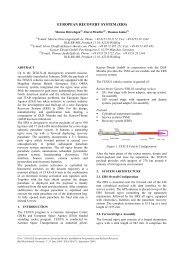
In cooperation with NASA and SSC, the first flight ever<br />
of an S19-guided single stage Black Brant VC rocket<br />
took place at Wallops Flight Facility on 10 Jan, 1976.<br />
The flight was a perfect success, and the S19 was<br />
recovered from the Atlantic (but re-used only as a<br />
museum object, since no efforts had been made to make<br />
the unit waterproof).<br />
The S19 was upgraded from prototype to commercial<br />
status already in 1977, and the first flight was followed<br />
by a second one in 1978 from Esrange. This time, a two<br />
stage configuration was being used with even higher<br />
wind tolerance than on the maiden flight. During<br />
subsequent years Esrange saw many guided scientific<br />
flights with apogees up to over 400 km. The upgraded<br />
system is seen in Fig 3<br />
Figure 1. Maiden S19 flight from Wallops FF<br />
Figure 2. Prototype S19 recovered from the Atlantic<br />
Ocean..<br />
Figure 3. The operative version uses a lightweight<br />
magnesium structure and upgraded internal equipment<br />
The analog S19 Boost Guidance System later became a<br />
money-saving cornerstone in NASAs high altitude<br />
space research flights at White Sands Missile Range,<br />
NM. A total of 185 flights were performed with the<br />
analogue S19 boost guidance systems, before they were<br />
finally retired in 2006. By then, superior alternatives<br />
had become available and used for many years.
2. ENTERING THE DIGITAL WORLD<br />
In the late eighties, European sounding rocket based<br />
research aimed for higher apogees and long duration<br />
flights. This was driven by the upcoming construction<br />
of the International Space Station, ISS, in which<br />
research related to micro-gravity is a cornerstone. To<br />
develop experiments and to perform basic research in<br />
this field, the German Texus programme had started, but<br />
in order to get longer periods of micro-gravity, a more<br />
powerful sounding rocket platform was needed.<br />
A goal was to achieve up to 15 minutes of high quality<br />
micro-gravity in a recoverable payload, consisting of<br />
several experiment modules. Such a long flight time of a<br />
heavy payload of course means a very high apogee and<br />
a powerful rocket motor. Recovering a heavy payload<br />
also means using a land range, in this case Esrange. To<br />
keep the impact point safely within the borderlines of<br />
Esrange, a control system for the new vehicle had to be<br />
developed. Though an S19 type canard control solution<br />
was possible, the final choice was to develop a Thrust<br />
Vector Control (TVC) system for the Castor 4B motor.<br />
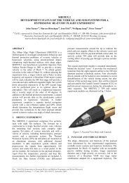
The name of the new sounding rocket was Maxus.<br />
The Guidance, Navigation and Control system for the<br />
Maxus was named GCS, and it was based upon the<br />
RIINS inertial navigation system built by Inertial<br />
Science Inc. The RIINS consisted of two parts: A<br />
despun platform with gyros and accelerometers, and a<br />
Navigation Processing Unit (NPU) that translated the<br />
output of these sensors to attitude angles & rates, as<br />
well as to position, velocity and acceleration. The third<br />
major component of the GCS was an in-house<br />
developed Guidance Processing Unit (GPU). The GPU<br />
used the navigational output signals in a guidance<br />
algorithm that provided stabilization, bending mode<br />
control and trajectory guidance for the Maxus rocket<br />
In these early days of digital engineering, 286 and 386<br />
processors were commonly used in home PC systems.<br />
The size and weight of the supporting electronics and<br />
their circuit boards were a lot more impressive than the<br />
capacity of these processors. For that reason, the RIINS,<br />
the NPU and the GPU pretty much filled up the volume<br />
available in the GCS unit seen in Fig 4.<br />
In spite of some initial vehicle difficulties related to the<br />
Castor’s thrust vector actuator, the GCS performed well<br />
during all launches, and micro-g experiment times<br />
above 13 minutes were achieved in a number of flights<br />
at Esrange, with apogee above 700 km.<br />
A most important safety feature of the Maxus is that the<br />
information provided by the GCS itself is integrated into<br />
the set of Range Safety tools at Esrange. In this system,<br />
a RUAG Aerospace engineer analyses navigation and<br />
Figure 4. First generation GCS for Maxus<br />
guidance diagrams as they grow in real time, and acts as<br />
an advisor to the Range Safety Officer. Flight path and<br />
gyro angles, instantaneous impact point (IIP), TVC<br />
deflections and pure status signals provide a full picture<br />
of how things are going during flight. This is a good<br />
way to make maximum use of flight safety information<br />
available.<br />
In parallel with the GCS, the SPINRAC and RACS<br />
systems for cold gas control of an upper stage and for<br />
payload pointing were also developed and successfully<br />
flown. These functions and their associated, flight<br />
qualified software remain available as add-ons for all<br />
RUAG Aerospace GNC systems.<br />
3. THE S19 GOES DIGITAL…<br />
Shortly after the first MAXUS flights, the RIINS was<br />
further refined into the much more compact and lighter<br />
DMARS inertial navigation system. The DMARS unit<br />
replaces the RIINS, the Navigation Unit and the<br />
Guidance Processing Unit. Taking advantage of the size<br />
reduction, the DMARS was made the heart of the DS19<br />
guidance, navigation and control system, which then<br />
became a second generation S19 Family system, and the<br />
first to exhibit digital guidance&control. The DS19 is a<br />
true “fire and forget” system that flies the vehicle to a<br />
preset impact point at very high precision, and does not<br />
rely on wind weighting or accurate launcher settings.<br />
Due to manoeuvrability restrictions at White Sands<br />
Missile Range, NM, a third generation S19 Family<br />
System was developed, with the DS19 as its starting<br />
point. It uses DS19 technology but S19 guidance
strategy. Due to the close similarity to the DS19 it was<br />
named the S19D.<br />
Figure 5. The DS19 fire-and-forget system<br />
To reduce the control system’s ability to perform rapid<br />
manoeuvres in the case of a hard-over failure, the S19D<br />
was created out of the DS19 by simply reducing the<br />
guidance time to 18 s. The S19D performs S19 type<br />
guidance, but at a much higher precision thanks to the<br />
DMARS. The S19D flight software also includes a<br />
much more efficient suppression of the vehicle’s elastic<br />
oscillations, which would otherwise reduce the guidance<br />
performance.<br />
Figure 6. The S19D<br />
As a consequence of the reduced guidance time, only<br />
one gas bottle is required. This reduces the total weight<br />
of the S19D by 1.0 kg as compared to the DS19, and by<br />
2.9 kg as compared by the analog S19. At the same<br />
time, the impact dispersion performance has been<br />
improved by a factor of four.<br />
4. …AND THE GCS IS IMPROVED<br />
Once the DS19 had proven its value, a second<br />
generation Maxus GCS system was developed, based<br />
upon the DMARS. The RIINS/NPU combination<br />
worked well during all their flights, but there were<br />
reliability issues that became apparent during system<br />
testing, making the first generation GCS a bit laborious<br />
and thus costly to use. The introduction of the DMARS<br />
was a big reliability improvement for the GCS. Also,<br />
the NPU and the GPU are no longer needed, since all<br />
navigational and flight software related calculations are<br />
now performed within the upper electronics section of<br />
the DMARS.<br />
Comparing Figs 4 and 7 shows the dramatic reduction<br />
achieved when replacing the RIINS, the Navigation<br />
Processing Unit and the Guidance Processing Unit with<br />
just the DMARS system. The redesign has reduced the<br />
total weight by more than 7 kg. The cost of the system<br />
also has been reduced, and so has the refurbishment<br />
cost, since many time-consuming tests were simplified,<br />
when the DMARS was introduced.<br />
Figure 7. Second generation GCS, using DMARS<br />
Needless to say, the second generation GCS has plenty<br />
of space available for additional apparatus. For<br />
example, RCS or ACS equipment could find a new<br />
home inside the GCS structure, and then maybe even<br />
use attitude data from the DMARS for control purposes.<br />
5. S19L, THE FOURTH GENERATION<br />
Although the S19D has fulfilled its guidance and control<br />
tasks flawlessly in its 13 launches to date, technological<br />
development has allowed for a fourth generation
member of the S19 Family of Guidance Systems to be<br />
born, the S19L. This system is centred on the LN200<br />
Inertial Measurement Unit. In contrast to the DMARS<br />
with its despun platform, the LN200 is a strap-down<br />
system. Its accuracy and sensing frequencies are high<br />
enough to provide sufficient stability margins in the<br />
vehicle control loop and to resolve all canard commands<br />
correctly during the guidance phase of the fast rolling<br />
rocket.<br />
In addition to performing the required boost guidance<br />
during 18 s, the S19L also provides navigational data<br />
such as position, velocity and Instantaneous Impact<br />
Point (IIP) information, using acceleration data from a<br />
package of accelerometers housed in the LN200. The<br />
use of solid state sensors (as opposed to a spinstabilized<br />
inertial navigation unit with mechanical<br />
gyros) has reduced the complexity of the S19L and thus,<br />
improved the over-all reliability of the system. With<br />
impact dispersion performance just barely below that of<br />
the S19D, the S19L has the advantages of lower weight<br />
and power consumption, easier handling, better system<br />
overview and last but not least, lower price. The weight<br />
of the S19L is 4.5 kg below that of the S19.<br />
Fig 8 shows two S19L units, both of which are actually<br />
converted S19 systems that re-use the main structure,<br />
the pneumatic system and some additional parts. The<br />
LN200 is located in the centre of the module, but due to<br />
its small size, it is hardly visible. Its output is<br />
conditioned and used by a small two circuit board<br />
Guidance Processing Unit (GPU) developed by RUAG<br />
Aerospace and DST Control of Linköping, Sweden. The<br />
time for system self-alignment is 2 min, as compared to<br />
7 min for the S19D. This feature further streamlines the<br />
countdown procedure.<br />
Figure 8. The S19L<br />
6. COMMON FEATURES<br />
RUAG Aerospace guidance, navigation and control<br />
systems provide the following major advantages:<br />
• Significantly improved impact dispersion<br />
performance, as compared to unguided vehicles,<br />
allows for high apogee / long duration flights at<br />
geographically limited rocket ranges.<br />
• High wind tolerance provide highly relaxed launch<br />
conditions, and the rocket can be launched when<br />
the scientist wants to, not when the weather<br />
situation so dictates. Typically, a Terrier-BBVC<br />
vehicle guided by the S19L can be safely launched<br />
into a wind profile of 10-15 m/s at ground level,<br />
increasing to 50 m/s at 10 km of altitude. The wind<br />
limits of the GCS guided Maxus are similarly high.<br />
• Recent systems provide an excellent single-screen<br />
overview of a multitude of system status and readyto-launch<br />
data during countdown and flight.<br />
• Situational awareness data for Range Safety,<br />
including heading, position and velocity data as<br />
well as in-flight instantaneous impact point<br />
prediction.<br />
• Navigational and pointing data for scientists and<br />
other users, for use on-line or during post flight<br />
data reduction exercises.<br />
• Recent systems also are lighter and more reliable<br />
than the early versions, and close-to-outdated<br />
technology has been replaced with currently<br />
available hardware.<br />
• System interfaces have become more standardized,<br />
such as RS232 and RS422 data interfaces.<br />
• Minimum battery capacity is 20 minutes. This<br />
means that navigational and attitude data remain<br />
available not only during guidance, but throughout<br />
the flight.<br />
• Finally, the cost of the newer systems is lower<br />
thanks to less complicated solutions. The same<br />
holds true for their refurbishment cost.<br />
7. FUTURE SYSTEMS<br />
The trend towards more capable guidance, navigation<br />
and control systems is likely to continue, following the<br />
general improvements of worldwide technology. Also,<br />
to remain available, future systems must be upgraded<br />
with up to date technology.<br />
Can the systems be made lighter and smaller? Not a<br />
whole lot, since the size and weight of the actuators<br />
reflect the size and weight of the sounding rocket they<br />
control. The actuators and their supporting components<br />
then dictate the size and weight of the outer structure.<br />
Minor reductions remain possible though, thanks to the
on-going miniaturization of electronics and battery<br />
cells.<br />
Looking at the whole payload, size and weight<br />
reductions are possible by integrating more functions<br />
into the guidance modules, such as telemetry and/or<br />
recovery system electronics.<br />
Also, by adding a low-cost cold gas module to any of<br />
the RUAG Aerospace guidance systems, the<br />
performance could include RCS, ACS and/or upper<br />
stage trajectory control capabilities. The cold gas<br />
module would only contain a gas supply, thruster valves<br />
and interface electronics. The guidance system’s inertial<br />
navigation sensor and additional RCS/ACS software<br />
resident in its guidance processing unit would provide<br />
commands for the thruster valves.<br />
8. FUTURE APPLICATIONS<br />
Guidance, navigation and control systems improve the<br />
flight time, the on-time launch probability and the<br />
impact dispersion of sounding rockets. With a guidance<br />
system onboard, the rocket is normally launched on the<br />
first day regardless of the wind situation, reducing range<br />
and personnel costs already in current applications. The<br />
following applications or research areas are likely to<br />
benefit from the additional flight time offered by<br />
guidance and control systems:<br />
• In-flight verification of experiment modules<br />
later to be launched on satellite missions, as<br />
well as calibration of experiments that already<br />
fly on satellites.<br />
• Astrophysics missions, where a telescope is<br />
pointed at an object of interest for as long a<br />
time as possible.<br />
• Extremely high apogee missions, in which an<br />
upper exo-atmospheric stage is stabilized after<br />
atmospheric exit, re-pointed and kept stable<br />
during motor burn. Apogees over 1000 km are<br />
quite possible, using already flight proven<br />
SPINRAC software as an add-on to the RUAG<br />
Aerospace guidance systems.<br />
• Tailored trajectories, again made possible by<br />
the re-pointing of an upper stage prior to<br />
ignition. Such trajectories can be useful for<br />
scramjet and other re-entry experiments, as<br />
well as for target missions in missile defence<br />
type applications.<br />
Some rocket ranges, such as the Australian Woomera<br />
rocket range and ranges that utilise vast oceanic areas<br />
for impact are currently considered large enough to<br />
allow for unguided launches. This situation may change<br />
for the following reasons:<br />
• Very high apogee, long duration flights may<br />
render even these large impact areas too small.<br />
• Extremely large impact areas cannot be<br />
completely cleared from people or valuable<br />
objects during a launch. The risk of damage to<br />
humans living in or travelling through very<br />
large impact areas during launch is not<br />
negligible. Boat and airplane traffic through<br />
oceanic ranges serve as examples.<br />
• Recovery in a remote oceanic area is very<br />
difficult, when the recovery vessels have to<br />
cover the vast search areas associated with<br />
unguided, high apogee flight.<br />
The solution to the above problems spells guidance,<br />
navigation and control.<br />
9. CONCLUSION<br />
An on-going development and refinement of multiple<br />
generations of guidance, navigation and control systems<br />
has been described. Trends of higher capacity, easier<br />
handling, better system overview, lower weight and<br />
lower cost have been demonstrated. The quality of onboard<br />
situational awareness data for Range Safety<br />
support and of attitude data for science support also has<br />
been greatly improved over the years.<br />
The further development of new guidance system<br />
generations is driven by technological achievements as<br />
well as by requirements of new applications, especially<br />
those that are associated with extremely high apogees<br />
and tailored trajectories.