developing a gliding spacecraft to flight over titan - Human ...
developing a gliding spacecraft to flight over titan - Human ...
developing a gliding spacecraft to flight over titan - Human ...

You also want an ePaper? Increase the reach of your titles
YUMPU automatically turns print PDFs into web optimized ePapers that Google loves.
ABSTRACT<br />
DEVELOPING A GLIDING SPACECRAFT TO FLIGHT OVER TITAN<br />
Jose M. Giron-Sierra, Hec<strong>to</strong>r Garcia de Marina, Fernando Pereda<br />
The target of our present research is <strong>to</strong> develop a<br />
<strong>gliding</strong> <strong>spacecraft</strong> with several possible uses, including<br />
the exploration of Titan. The vehicle has a profile<br />
similar <strong>to</strong> a ray fish, and offers encouraging<br />
performances for long <strong>gliding</strong> trajec<strong>to</strong>ries. The paper<br />
describes several aspects of the research: application<br />
scenarios, development of the on-board system for<br />
au<strong>to</strong>nomous <strong>flight</strong> and simultaneous data acquisition,<br />
intelligent path planning, and preliminary mission<br />
analysis for the next experiment: <strong>to</strong> be drop from a<br />
balloon.<br />
1. INTRODUCTION<br />
A possible alternative for the exploration of Titan in<br />
the 2020, by ESA, is <strong>to</strong> use a <strong>gliding</strong> <strong>spacecraft</strong>. This is<br />
the subject of our project, recently started. The ratio<br />
between atmosphere density and gravity near Titan<br />
surface is high enough <strong>to</strong> favour the use of a glider.<br />
Figure 1. Titan<br />
Our project is conceived at this moment as an academic<br />
research, with the help of students. The project has<br />
been selected by ESA Education for the next BEXUS<br />
experiment, autumn 2009. For the long-term<br />
development effort we count with the support of Dr.<br />
Guillermo Ortega and Eng. Nuno Felipe, ESA ESTEC.<br />
To arrive <strong>to</strong> a candidate vehicle for Titan, we need <strong>to</strong><br />
proceed step by step. Our next step is <strong>to</strong> develop a<br />
version of the glider for experimental testing in our<br />
Dep. ACYA, Fac. Fisicas. Universidad Complutense de Madrid<br />
28040 Madrid, Spain. gironsi@dacya.ucm.es<br />
planet. The vehicle will be drop from a balloon, at 15<br />
km high at Kiruna.<br />
A development process is being executed <strong>to</strong> create the<br />
glider for the BEXUS experiment. This paper describes<br />
the most important aspects of the development.<br />
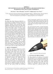
2. THE GLIDER<br />
___________________________________________________________________________________<br />
Proc. ‘19th ESA Symposium on European Rocket and Balloon Programmes and Related Research,<br />
Bad Reichenhall, Germany, 7–11 June 2009 (ESA SP-671, September 2009)<br />
A special <strong>spacecraft</strong> has been selected, which has the<br />
profile of a fish and behaves as a lifting body with little<br />
wing span (Fig.2). This vehicle has low drag and very<br />
good manoeuvrability at low (0.05 Match) and high<br />
(0.8 Match) speeds. The designer of the vehicle, named<br />
`SpaceFish’ is Eng. Koni Schafroth.<br />
Figure 2, Smartfish<br />
Figure 3 and 4 show aerodynamic characteristics of the<br />
vehicle, which can be seen as a combination of glider<br />
and subsonic aircraft. It owns great stability<br />
performance by low wingspan.<br />
Figure 3. Pitching moment of the vehicle
Figure 4. L/D relation of the vehicle<br />
A particular version of the vehicle is under<br />
development for the BEXUS experiment. Here are the<br />
aircraft characteristics:<br />
• Dimensions:<br />
o Wingspan: 1m<br />
o Length: 1.40m<br />
o Height: 0.30m<br />
• Weight:<br />
o Empty plane: 3.5Kg<br />
o Payload: 2-3Kg<br />
• Material:<br />
o Glass-fiber sandwich:<br />
Outer layer: 2x150g/m 2 glass<br />
fiber<br />
Middle layer: 3mm of foam<br />
Inner layer: 1x150g/m 2 glass<br />
fiber<br />
The moulds of the aircraft have been carved with<br />
precision CNC. To gain confidence with the use of the<br />
moulds, a first mock-up has been built. This mock-up<br />
is now in use by our team for constructive decisions<br />
about aircraft internals: where and how <strong>to</strong> fix the<br />
servos, where <strong>to</strong> put the batteries, get an idea for<br />
parachute placing, mind the location of the centre of<br />
gravity, etc.<br />
A second, lighter aircraft has been built: this time for<br />
flying testing. Fig. 5 shows a pho<strong>to</strong>graph of the aircraft<br />
being taken from the mould; some of the students<br />
belonging <strong>to</strong> the development team appear in the<br />
pho<strong>to</strong>graph.<br />
A complete professional simulation study has been<br />
already done by ESA, <strong>to</strong> check the performance of the<br />
<strong>spacecraft</strong>. The results are encouraging. We expect<br />
1km of fall for every 10km of advance. Fig. 6 shows a<br />
screenshot of the <strong>flight</strong> simulation, <strong>over</strong> Kiruna zone.<br />
Figure 5. An SpaceFish exemplar being taken<br />
from its mould.<br />
Figure 6. Screenshot of the 3D <strong>flight</strong> simulation<br />
3. SCENARIOS<br />
The development considers several scenarios for<br />
gradual approach <strong>to</strong> be ready for missions.<br />
There is a set of experimental tasks for testing. The<br />
vehicle is put on <strong>to</strong>p of a car, and driven at 120 km/h,<br />
for the testing of the speed sensors, which are based on<br />
air pressure measurement. The complete vehicle, with
on-board electronics is put in<strong>to</strong> a research refrigera<strong>to</strong>r,<br />
able <strong>to</strong> reach -70ºC since this is the temperature we<br />
expect in the BEXUS experiment.<br />
The first flyable SpaceFish is being equipped with a<br />
ducted fan propeller. We need it <strong>to</strong> be able <strong>to</strong> take off<br />
from a runway. A particular runway, property of a R/C<br />
society, has been located 50 Km from Madrid, in a<br />
place with no buildings nor roads in 10 Km around.<br />
Batteries have been added <strong>to</strong> the vehicle, for the ducted<br />
fan, so weight increases. An experimental plan has<br />
been designed, for separate testing of the main parts of<br />
the BEXUS <strong>flight</strong>: straight <strong>gliding</strong>, turns, final<br />
approach and landing. The tests are first made by R/C<br />
control, <strong>to</strong> take data. Initial trimming of the vehicle will<br />
be done in this manner. Afterwards, this is substituted<br />
by au<strong>to</strong>nomous control. Fig. 7 shows a pho<strong>to</strong>graph of<br />
the runway<br />
Figure 7. The runway for <strong>flight</strong> testing<br />
We got a 3m diameter balloon, and we made a<br />
gondola. The plan is <strong>to</strong> be able <strong>to</strong> test the initial part of<br />
the BEXUS experiment, which is <strong>to</strong> let the vehicle fall<br />
and rec<strong>over</strong> stable <strong>flight</strong>. Several types of ropes and<br />
wires will be used <strong>to</strong> ensure that the balloon will not<br />
escape.<br />
Another SpaceFish is under construction, since we<br />
want <strong>to</strong> have two exemplars when at Kiruna.<br />
After the testing campaign, it is expected <strong>to</strong> conduct<br />
this autumn the BEXUS experiment from 15Km high<br />
using a balloon, as shown in fig. 8. The purpose of the<br />
experiment is <strong>to</strong> let the vehicle glide along a<br />
programmed trajec<strong>to</strong>ry, for the testing of flying<br />
qualities, and for taking data: evolution of pressures,<br />
altitude, attitude, speed, cog motion.<br />
Figure 8. The BEXUS balloon<br />
The research will continue in several fronts: more<br />
testing of the vehicle, with possible design changes;<br />
improvements of the on board system for <strong>flight</strong> control<br />
and for data acquisition, improvements in the path<br />
planning methodology, advances in the simulation and<br />
analysis <strong>to</strong>ols, advances in the external support from<br />
ground. Let us insist in that the vehicle has au<strong>to</strong>nomous<br />
control; the ground support is for telemetry, getting<br />
data from the vehicle.<br />
Main aspects of the Titan scenario are that the vehicle<br />
will behave as a re-entry vehicle at the beginning, and<br />
gradually will transition <strong>to</strong> <strong>gliding</strong> for high altitude<br />
exploration; and that an intelligent real-time path<br />
planner, we denote `SmartPath’, will be used <strong>to</strong> adapt<br />
the glider trajec<strong>to</strong>ry <strong>to</strong> targets being recognized as<br />
interesting during the <strong>flight</strong>. Other functions of<br />
SpacePath are optimization of power consumption, and<br />
improvements of exploration area c<strong>over</strong>age.<br />
The glider is able <strong>to</strong> rec<strong>over</strong> altitude by using, from<br />
time <strong>to</strong> time, a propeller. We think that in an<br />
exploration mission it would be interesting <strong>to</strong> approach<br />
places of interest, or rec<strong>over</strong> attitude in zones with less<br />
interest. So we are starting <strong>to</strong> develop an on-board<br />
optimizer for this task. The optimizer combines a rule<br />
base with the on-board control, taking in<strong>to</strong> account<br />
operability restrictions. In addition we plan <strong>to</strong> be able<br />
<strong>to</strong> drop from the vehicle probes/transponders.
4. ON-BOARD SYSTEM<br />
As said before, the <strong>spacecraft</strong> will have au<strong>to</strong>nomous<br />
control during the BEXUS experiments and in next<br />
applications, but for initial experiments an external<br />
supervisory system is also advisable. Therefore, in<br />
addition <strong>to</strong> a radio data link from the <strong>spacecraft</strong> <strong>to</strong> the<br />
ground station, there is a conventional R/C channel<br />
from the ground station <strong>to</strong> the <strong>spacecraft</strong>, being able <strong>to</strong><br />
<strong>over</strong>ride the au<strong>to</strong>nomous <strong>flight</strong> control, so a human<br />
opera<strong>to</strong>r can intervene in exceptional situations.<br />
The on-board system includes three subsystems.<br />
a) Navigation subsystem:<br />
Figure 9. Block diagram of<br />
the control system<br />
This subsystem employs pressure sensors, an<br />
inertial unit with accelerometers and<br />
magne<strong>to</strong>meters, and GPS. Kalman filtering is<br />
used for data fusion. The World Magnetic<br />
Model is also used.<br />
The subsystem control the <strong>spacecraft</strong> rudders,<br />
and in some experiments the ducted fan.<br />
The <strong>flight</strong> control software has a script that<br />
describes the mission plan, a script interpreter,<br />
and a set of <strong>flight</strong> control primitives.<br />
b) Data acquisition subsystem:<br />
All data from sensors are recorded with a time<br />
stamp. A video camera is included. The data<br />
are saved in a on-board card, similar <strong>to</strong> the<br />
cards used in digital cameras.<br />
Selected data are transmitted <strong>to</strong> the ground<br />
station via digital radio link.<br />
c) Safety subsystem:<br />
It may happen that dropping from the balloon<br />
the vehicle could not reach controlled <strong>flight</strong>.<br />
Therefore a free-fall detection system is<br />
provided, using accelerometer.<br />
Other navigation problems may occur during<br />
the experiments, like electronic faults in the<br />
on-board system. A supervisory circuit is<br />
provided, acting as watch dog.<br />
Faults in the communication system could<br />
also appear. They are detected in the ground<br />
station.<br />
A parachute is embodied in<strong>to</strong> the vehicle as a<br />
safety measure. Any crucial problem will<br />
result in the parachute <strong>to</strong> be deployed. The<br />
safety subsystem is in charge of that.<br />
The safety subsystem is independent from the<br />
<strong>flight</strong> and data acquisition subsystems, with<br />
independent power supply.
The ground station has two functions. One is <strong>to</strong><br />
moni<strong>to</strong>r and display the data being received from the<br />
flying vehicle. The second includes a panic but<strong>to</strong>n, and<br />
manual R/C control.<br />
Fig. 9 shows a block diagram of the complete system.<br />
5. DEVELOPMENT ASPECTS<br />
An important part of the research is <strong>to</strong> develop an<br />
animated 3D simulation environment, and the software<br />
for the on-board control system and for the external<br />
supervisory system. All these software units share<br />
common modules.<br />
The simulation can include several terrains, using<br />
Google Earth. The simulation environment is<br />
experimentally validated.<br />
Testing along development steps required a lot of<br />
imagination. For instance, the artificial horizon that<br />
will be part of the supervisory ground station has been<br />
tested with a WII racquet. Several conventional R/C<br />
airplanes, of the Cessna type, have been used for<br />
telemetry and au<strong>to</strong>pilots testing, etc, some of them<br />
were lost in the battle.<br />
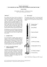
6. PLANNING OF THE BEXUS MISSION<br />
The BEXUS experiment has been analyzed in order <strong>to</strong><br />
establish main phases, and a description in terms of onboard<br />
script.<br />
The central part of the <strong>flight</strong> will be devoted <strong>to</strong> repeat a<br />
trajec<strong>to</strong>ry with the form of an 8. The arc of the 8 has<br />
500m radius, and the straight branches of the 8 are 2km<br />
long. Along an 8 the glider may descend about 600m.<br />
The main phases of the experiment are drop and stable<br />
control taking, approaching <strong>to</strong> a delimited zone for the<br />
8’s, point <strong>to</strong> the landing site and approaching along 20<br />
km, final landing with the help of the parachute.<br />
The on-board control for speed, pitch and roll, would<br />
be based on rules, for a sort of gain-scheduling<br />
according with the changes of air density along the<br />
descent.<br />
Fig. 10 shows the footprint of the landing site.<br />
Figure 10. Footprint of the landing site<br />
The experiment will be moni<strong>to</strong>red from the ground<br />
station by digital radio link able <strong>to</strong> reach 50 km<br />
distance.<br />
6. CONCLUSION<br />
This paper briefly described main traits of our research<br />
on a glider, in order <strong>to</strong> examine its performances as a<br />
candidate for planetary exploration.<br />
The research uses a <strong>spacecraft</strong> with the form of a fish,<br />
enjoying good properties as a glider and as re-entry<br />
vehicle.<br />
Main parts of the system, and steps of the development<br />
has been described.<br />
The near future has a clear target, <strong>to</strong> investigate in<br />
detail the flying qualities of the vehicle in several<br />
atmospheric and environmental conditions, and <strong>to</strong><br />
develop adequate au<strong>to</strong>nomous control, with intelligent<br />
real time path planning, for non Earth scenarios.