

Push Button Panels PP7, PP17-I, PP17-II - Siemens Industry Online ...
Push Button Panels PP7, PP17-I, PP17-II - Siemens Industry Online ...
Push Button Panels PP7, PP17-I, PP17-II - Siemens Industry Online ...

You also want an ePaper? Increase the reach of your titles
YUMPU automatically turns print PDFs into web optimized ePapers that Google loves.
2.2 Define Configuration in PLC<br />
2.2.1 MPI connection<br />
2.2.2 PROFIBUS-DP connection<br />
2-6<br />
If connection type MPI is used for the <strong>Push</strong> <strong>Button</strong> Panel, no hardware configuration<br />
is necessary. Only the MPI address needs to be set on the <strong>Push</strong> <strong>Button</strong><br />
Panel.<br />
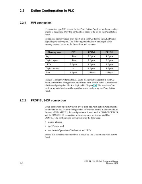
Interrelated memory areas must be set up in the PLC for the keys, LEDs and<br />
digital inputs and outputs. The following table indicates the length of the<br />
memory areas to be set up for the various unit versions.<br />
Memory area <strong>PP7</strong> <strong>PP17</strong>-I <strong>PP17</strong>-<strong>II</strong><br />
Keys 1 Byte 2 Bytes 4 Bytes<br />
Digital inputs 1 Byte 2 Bytes 2 Bytes<br />
LEDs 2 Bytes 4 Bytes 8 Bytes<br />
Digital outputs – 4 Bytes 4 Bytes<br />
Total 4 Bytes 12 Bytes 18 Bytes<br />
In order to modify system settings, a data block must be created in the PLC<br />
which contains the configuration data for the <strong>Push</strong> <strong>Button</strong> Panel. The structure<br />
of this configuring data block is depicted in Chapter 2.4. The number of the<br />
configuring data block must be specified when configuring the <strong>Push</strong> <strong>Button</strong><br />
Panel.<br />
When connection type PROFIBUS-DP is used, the <strong>Push</strong> <strong>Button</strong> Panel must be<br />
installed in the PROFIBUS configuration software as a slave in the network. In<br />
the case of SIMATIC S5, the configuration software used is COM-PROFIBUS,<br />
and for SIMATIC S7 connection to the network is performed via HW-<br />
CONFIG. The configuration software defines the following:<br />
station address,<br />
the I/O area used<br />
and the configuration of the buttons and LEDs.<br />
Ensure that the same station address is specified that is set on the <strong>Push</strong> <strong>Button</strong><br />
Panel.<br />
<strong>PP7</strong>, <strong>PP17</strong>-I, <strong>PP17</strong>-<strong>II</strong> Equipment Manual<br />
Release 06/98


