RMX 2000 Quick Installation A3 V7.7.fm - Polycom
RMX 2000 Quick Installation A3 V7.7.fm - Polycom
RMX 2000 Quick Installation A3 V7.7.fm - Polycom

Create successful ePaper yourself
Turn your PDF publications into a flip-book with our unique Google optimized e-Paper software.
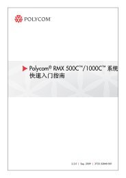
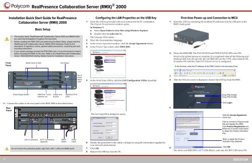
<strong>Installation</strong> <strong>Quick</strong> Start Guide for RealPresence<br />
Collaboration Server (<strong>RMX</strong>) <strong>2000</strong><br />
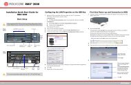
Front<br />
Panel<br />
Basic Setup<br />
>> Connect the cables to the rear panel of the <strong>RMX</strong> <strong>2000</strong> as described below:<br />
Rear<br />
Panel<br />
• The product name, RealPresence® Collaboration Server <strong>2000</strong> and <strong>RMX</strong>® <strong>2000</strong><br />
are used interchangeably throughout this document.<br />
• Before installing the <strong>RMX</strong> <strong>2000</strong> and performing the Basic Setup, please read the<br />
RealPresence® Collaboration Server (<strong>RMX</strong>) <strong>2000</strong> Hardware Guide for the<br />
description of regulatory notices, general safety precautions, unpacking and rack<br />
mounting instructions.<br />
• If your system package includes the RTM ISDN card, it is recommended to install it<br />
before mounting the <strong>RMX</strong> on the rack. Refer to the RealPresence® Collaboration<br />
Server 1500/<strong>2000</strong>/4000 Getting Started Guide for <strong>Installation</strong> instructions.<br />
ERR RDY ACT HS<br />
ERR RDY ACT<br />
Media Cards & LEDs Fan Drawer<br />
<strong>RMX</strong> <strong>2000</strong><br />
FAN<br />
STATUS<br />
PWR<br />
STATUS<br />
PWR ERR RDYACT HD HS<br />
FANS<br />
CNTL<br />
Power Supply Drawer USB Ports - not for Control Unit<br />
customer use & LEDs<br />
LAN 2 Connection<br />
RealPresence Collaboration Server (<strong>RMX</strong>) ® <strong>2000</strong><br />
E1/T1 Connections<br />
(Optional)<br />
Do not remove the protective plastic caps from LAN1, LAN3 and ShMG ports.<br />
HS<br />
MPM+80<br />
MPM+80<br />
CNTL<br />
Off/On<br />
Switch<br />
Optional CPU &<br />
LEDs<br />
Power<br />
Cable<br />
Fan &<br />
Power<br />
Status<br />
LEDs<br />
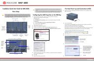
Configuring the LAN Properties on the USB Key<br />
1 Insert the USB key provided with your system into the PC workstation.<br />
The <strong>Polycom</strong> Documentation window opens.<br />
In Windows 7:<br />
a Select Open Folder to view files using Windows Explorer.<br />
b Double-click the index.hta file.<br />
The Language Menu opens.<br />
2 Select the documentation language.<br />
3 In the License Agreement window, click the Accept Agreement button.<br />
4 In the Product Type screen, select <strong>RMX</strong> <strong>2000</strong>.<br />
5 In the Initial Setup Utility, click the LAN Configuration Utility hyperlink.<br />
The LanConfigUtility dialog box opens.<br />
6 Modify the parameters in the utility’s dialog box using the information supplied by<br />
your network administrator.<br />
7 Click OK.<br />
8 Remove the USB key from the PC.<br />
First-time Power-up and Connection to MCU<br />
1 Insert the USB key containing the modified IP addresses into the USB port on the<br />
<strong>RMX</strong>’s back panel.<br />
2 Power the <strong>RMX</strong> ON. The FAN STATUS and PWR STATUS LEDs turn ON.<br />
Wait for the upload process to complete. It is completed when all the flickering and<br />
flashing LEDs turn off and only the red ERR LED (on the CTNL unit) remains ON.<br />
It remains ON until the Default IP Network Service is configured.<br />
3<br />
4 After the Welcome screen is displayed, remove the USB key from the <strong>RMX</strong>.<br />
5<br />
In the browser, enter the IP address of the <strong>RMX</strong> Control Unit and press Enter.<br />
Enter POLYCOM.<br />
Enter POLYCOM.<br />
Click Login.<br />
Click the Accept Agreement<br />
check box.<br />
Click to connect to <strong>Polycom</strong> web<br />
site and register the <strong>RMX</strong>.<br />
Click Product Registration and<br />
follow the on screen instructions<br />
to obtain the Product Activation<br />
Key.<br />
Enter or paste the Product<br />
Activation Key obtained.<br />
6<br />
Click OK.<br />
The Media card ERR/RDY/ACT LEDs flicker, until only the RDY LED turns ON.<br />
.<br />
1 DOC2723A
RealPresence Collaboration Server (<strong>RMX</strong>) ® <strong>2000</strong><br />
Initial System Configuration<br />
This section describes the definition of H.323 Network Service, setting the <strong>RMX</strong> time,<br />
modifying the default Administrator user and setting basic system flags. For detailed<br />
description of H.323, SIP and ISDN Network Service definitions, see the RealPresence<br />
Collaboration Server (<strong>RMX</strong>) 1500/<strong>2000</strong>/4000 Getting Started Guide, “First Time <strong>Installation</strong><br />
and Configuration”.<br />
>> In the Fast Configuration Wizard, select Next to move from one window to another.<br />
1<br />
2 In the Routers tab, in the Default Router IP address IPv4 field, enter the IP address<br />
of the default router and click Next.<br />
Optional. Define the DNS server<br />
properties:<br />
• Registration mode<br />
• The name of the MCU<br />
domain<br />
• The static IP address of the<br />
primary DNS server<br />
3<br />
4 In the Network Type tab, IP Network Type field, select H.323 and click Next.<br />
5<br />
IPv4 is the default protocol for setting the Network Service in the Fast Configuration<br />
Wizard.<br />
Change the default service name if<br />
required.<br />
Enter the address to be used by IP<br />
endpoints when dialing in to the<br />
MCU.<br />
Enter the IP address(es) of the<br />
media card(s).<br />
Enter the subnet mask of the MCU.<br />
Enter the name of the MCU on<br />
the network.<br />
Optional. Select Specify to<br />
define a DNS server.<br />
Select Specify to configure the<br />
gatekeeper parameters.<br />
Enter gatekeeper’s host name<br />
or IP address.<br />
Enter the string with which the<br />
MCU registers itself with the<br />
gatekeeper.<br />
Enter the alias that identifies<br />
the <strong>RMX</strong>’s Signaling Host within<br />
the network. Up to five aliases<br />
can be defined for each <strong>RMX</strong>.<br />
Enter the user name and<br />
password the Collaboration<br />
Server will use to authenticate<br />
itself with the gatekeeper. The<br />
name and password must be<br />
defined in the gatekeeper.<br />
6<br />
7 Click the Save & Continue button.<br />
8 In the IP Network Service creation confirmation window, click OK.<br />
9<br />
10<br />
11<br />
Select this check box only if the<br />
authentication is enabled on the<br />
gatekeeper, to enable the<br />
Collaboration Server to register<br />
with the gatekeeper. Otherwise,<br />
skip this tab.<br />
Option 1: Using the arrows, set<br />
the GMT Time on the <strong>RMX</strong>.<br />
Using the arrows, set the time<br />
zone difference between<br />
Greenwich and the <strong>RMX</strong>’s<br />
physical location.<br />
Option 2: Click to automatically<br />
update the <strong>RMX</strong>'s GMT Date,<br />
Time and Offset to match that of<br />
the workstation.<br />
Option 3: Select this check box<br />
to synchronize <strong>RMX</strong> time with up<br />
to three external NTP servers<br />
and enter their IP addresses.<br />
Enter the new user name of the<br />
new administrator user.<br />
Enter the password for the new<br />
administrator user.<br />
Enter the new password again<br />
to confirm the new password.<br />
Optional. Modify the default<br />
settings of the system flags<br />
that define the general<br />
system behavior such as the<br />
number of digits in the<br />
conference ID assigned by<br />
the MCU.<br />
These flags can be modified<br />
later, if required, by clicking<br />
Setup menu > System<br />
Configuration.<br />
12 Click Save & Close.<br />
13 In the Success Message box confirming successful configuration, click OK.<br />
14 In the Reset Confirmation dialog box, click Yes.<br />
15 In the Please wait for system reset message box, click OK.<br />
System restart may take up to 10 minutes.<br />
16 Refresh the browser periodically until the Login screen is displayed and Login.<br />
In the Main Screen an MCU State indicator displays the time remaining until the<br />
system start-up is complete.<br />
When the default <strong>RMX</strong> User is replaced and the <strong>RMX</strong> Time is set and if there are no<br />
System Errors, the green RDY LED on the <strong>RMX</strong>’s front panel turns ON and the red ERR<br />
LED turns OFF.<br />
Connecting to a Conference Directly or via Entry Queue<br />
The RealPresence Collaboration Server (<strong>RMX</strong>) is shipped with pre-configured default CP<br />
(AVC) conferencing entities that can be used to dial in and start conferences. Default<br />
(Transit) Entry Queue ID: 1000, default Meeting Room IDs: 1001, 1002, 1003, and 1004.<br />
H.323 Participants<br />
Dial: [MCU Prefix in Gatekeeper][Conference or Entry Queue ID/Name]<br />
For example, if the MCU prefix in the gatekeeper is 925, enter 925 or 9251000 to connect<br />
to the EQ or 9251001/2/3/4 to connect directly to the conference. When connected to<br />
the EQ, enter the destination Meeting Room ID (i.e. 1001, 1002, 1003 or 1004).<br />
Alternatively, use the EQ or conference name. For example, if the conference name is<br />
Maple_Room, the participant can dial: 925Maple_Room.<br />
SIP Participants<br />
Dial: conference_routing _name@domain_name. Conference routing name must be<br />
registered with the SIP server. For example, enter 1001@polycom.com if conference<br />
routing name is 1001 and the domain name is polycom.com.<br />
ISDN and PSTN Participants<br />
Dial one of the numbers assigned to the conference, Meeting Room or Entry Queue with<br />
the required country and area code. When connected to an EQ you are routed to the<br />
conference according to the destination conference ID you enter.<br />
For example, if the assigned dial in number is 4045555, they dial this number with the<br />
appropriate area code (for example, 678) and country code (001).<br />
Conference Control Using DTMF Codes<br />
Operation<br />
DTMF<br />
String<br />
Operation<br />
DTMF<br />
String<br />
Start Click&View to modify<br />
personal layout<br />
** Play Help Menu *83<br />
Mute My Line *6 Request private assistance *0<br />
Unmute My Line #6 Request assistance for conference 00<br />
Increase Broadcast Volume *9 Increase Listening Volume *76<br />
Decrease Broadcast Volume #9 Decrease Listening Volume #76<br />
Invite Participant *72 Change To Chairperson *78<br />
Disconnect last invited participant #72 Show Number of Participants *88<br />
2 DOC2723A