RMX 1500 Hardware Guide.book - Polycom
RMX 1500 Hardware Guide.book - Polycom
RMX 1500 Hardware Guide.book - Polycom

You also want an ePaper? Increase the reach of your titles
YUMPU automatically turns print PDFs into web optimized ePapers that Google loves.
<strong>Polycom</strong> ® <strong>RMX</strong> ® <strong>1500</strong><br />
<strong>Hardware</strong> <strong>Guide</strong><br />
Version 4.7.2 | May 2011 | DOC2632A
Trademark Information<br />
<strong>Polycom</strong>®, the <strong>Polycom</strong> “Triangles” logo, and the names and marks associated with <strong>Polycom</strong>’s<br />
products are trademarks and/or service marks of <strong>Polycom</strong>, Inc., and are registered and/or<br />
common-law marks in the United States and various other countries.<br />
All other trademarks are the property of their respective owners.<br />
Patent Information<br />
The accompanying product is protected by one or more U.S. and foreign patents and/or pending<br />
patent applications held by <strong>Polycom</strong>, Inc.<br />
© 2011 <strong>Polycom</strong>, Inc. All rights reserved. <br />
<strong>Polycom</strong>, Inc.<br />
4750 Willow Road<br />
Pleasanton, CA 94588-2708<br />
USA<br />
No part of this document may be reproduced or transmitted in any form or by any means,<br />
electronic or mechanical, for any purpose, without the express written permission of <strong>Polycom</strong>, Inc.<br />
Under the law, reproducing includes translating into another language or format.<br />
As between the parties, <strong>Polycom</strong>, Inc., retains title to and ownership of all proprietary rights with<br />
respect to the software contained within its products. The software is protected by United States<br />
copyright laws and international treaty provision. Therefore, you must treat the software like any<br />
other copyrighted material (e.g., a <strong>book</strong> or sound recording).<br />
Every effort has been made to ensure that the information in this manual is accurate. <strong>Polycom</strong>, Inc.,<br />
is not responsible for printing or clerical errors. Information in this document is subject to change<br />
without notice.
Table of Contents<br />
<strong>Polycom</strong> <strong>RMX</strong> <strong>1500</strong> <strong>Hardware</strong> <strong>Guide</strong><br />
<strong>Hardware</strong> Description . . . . . . . . . . . . . . . . . . . . . . . . . . 1-1<br />
Main Features .......................................................................................... 1-1<br />
<strong>RMX</strong> <strong>1500</strong> Specifications ....................................................................... 1-2<br />
<strong>RMX</strong> <strong>1500</strong> System Capacities ................................................................ 1-3<br />
Conferencing Capacities ........................................................ 1-3<br />
Resource Capacities ................................................................ 1-5<br />
Site Requirements ................................................................................... 1-6<br />
Safety Requirements ...................................................................... 1-6<br />
Rack Mount Safety Precautions .................................................... 1-6<br />
Installation Precautions ................................................................. 1-7<br />
Installing the <strong>RMX</strong> <strong>1500</strong> ................................................................. 1-8<br />
Unpacking the <strong>RMX</strong> <strong>1500</strong> ...................................................... 1-8<br />
Mounting the <strong>RMX</strong> <strong>1500</strong> in a Rack ...................................... 1-9<br />
Connecting the <strong>RMX</strong> <strong>1500</strong> to a Power Source .......................... 1-10<br />
Connecting the <strong>RMX</strong> <strong>1500</strong> to AC Power ........................... 1-11<br />
Connecting Cables to the <strong>RMX</strong> <strong>1500</strong> .......................................... 1-12<br />
First-time Power-up ..................................................................... 1-12<br />
<strong>RMX</strong> <strong>1500</strong> Components ....................................................................... 1-14<br />
<strong>RMX</strong> <strong>1500</strong> Front Panel ................................................................. 1-14<br />
Opening the <strong>RMX</strong> <strong>1500</strong> Front Panel .................................. 1-14<br />
Front Panel Components ..................................................... 1-15<br />
<strong>RMX</strong> <strong>1500</strong> Rear Panel ................................................................... 1-16<br />
RTM IP <strong>1500</strong> .......................................................................... 1-16<br />
RTM ISDN <strong>1500</strong> .................................................................... 1-18<br />
ISDN/PSTN Clock Source .................................................. 1-20<br />
<strong>RMX</strong> <strong>1500</strong> Power Supply ............................................................. 1-20<br />
Power Supply LEDs ............................................................. 1-20<br />
<strong>RMX</strong> <strong>1500</strong> LEDs .................................................................................... 1-21<br />
<strong>RMX</strong> <strong>1500</strong> Front Panel LEDs ....................................................... 1-21<br />
<strong>RMX</strong> <strong>1500</strong> Rear Panel LEDs ........................................................ 1-22<br />
RTM IP <strong>1500</strong> LEDs ................................................................ 1-22<br />
RTM ISDN <strong>1500</strong> LEDS ......................................................... 1-24<br />
Power Supply LEDs ............................................................. 1-24<br />
i
Table of Contents<br />
ii<br />
Component Installation & Replacement . . . . . . . . . . . . 2-1<br />
Installing the RTM ISDN <strong>1500</strong> Card ............................................ 2-2<br />
Component Replacement ...................................................................... 2-4<br />
Replacing the RTM ISDN <strong>1500</strong> ..................................................... 2-5
<strong>Hardware</strong> Description<br />
Main Features<br />
1<br />
This <strong>Hardware</strong> <strong>Guide</strong> provides information on the <strong>RMX</strong> <strong>1500</strong> and its<br />
components. This system utilizes a modular platform, whose<br />
components are designed for high performance, capacity and reliance.<br />
The <strong>Polycom</strong> <strong>RMX</strong> <strong>1500</strong> offers the following features:<br />
• Linux® based<br />
• Chassis based on the ATCA standard<br />
• Support for standard network interfaces (H.323, SIP video, ISDN,<br />
PSTN and LAN)<br />
• New hardware technologies<br />
• Telco grade high availability, on-line upgrading and dynamic<br />
resource allocation<br />
• Easy integration of conference elements into external network<br />
management<br />
• Enhanced Continuous Presence (multi-image video)<br />
• IVR (Interactive Voice Response) module<br />
1-1
Chapter 1-<strong>Hardware</strong> Description<br />
<strong>RMX</strong> <strong>1500</strong> Specifications<br />
1-2<br />
Table 1-1 <strong>Polycom</strong> <strong>RMX</strong> <strong>1500</strong> Specifications<br />
Physical<br />
Height 1U (4.44 cm.)<br />
Width 19” (48.26 cm.)<br />
Depth 23.6” (60 cm.)<br />
Weight Up to 12 Kg.<br />
Media Protocols<br />
Audio G.711, G. 719, G.722, G.722.1, G.729A, G.723.1,<br />
Siren14, Siren 22.<br />
Video H.261, H.263, H.264.<br />
Network Interfaces<br />
IP, ISDN, PSTN and LAN H.323, SIP, ISDN, PSTN and LAN<br />
Power Supply<br />
AC Input/ Range, BTU Voltage range: 100-240 VAC ±10%, 47-63 Hz.<br />
Maximum BTU output: 3400 per hour.<br />
Power Consumption<br />
AC Maximum Power<br />
consumption<br />
Environment<br />
350 Watts.<br />
Operating temperature 0°– 40°C (22°– 104°F).<br />
Storage temperature -40°– 70°C (-40°– 158°F).<br />
Relative humidity 15% - 90% no condensing.<br />
Operating altitude Up to 4,500 m (15,000 ft.).<br />
Operating ESD 4 kV.
<strong>RMX</strong> <strong>1500</strong> System Capacities<br />
Conferencing Capacities<br />
<strong>Polycom</strong> <strong>RMX</strong> <strong>1500</strong> <strong>Hardware</strong> <strong>Guide</strong><br />
The following table summarizes the different system capacities.<br />
Table 1-2 System Functions and Capacities <strong>RMX</strong> <strong>1500</strong> Series<br />
System Functions MPMx - Q MPMx -S MPMx -D<br />
Maximum number of Video participants<br />
in a conference<br />
Maximum number of PSTN participants<br />
in a conference<br />
Maximum number of VOIP participants<br />
in a conference<br />
Maximum number of Audio calls per<br />
second<br />
Maximum number of Video calls per<br />
second<br />
25 45 90<br />
90 120 120<br />
90 180 360<br />
5 5 5<br />
2 2 2<br />
Maximum number of conferences 200 400 400<br />
Maximum number of Meeting Rooms 1000 1000 1000<br />
Maximum number of Entry Queues 40 40 40<br />
Maximum number of Profiles 40 40 40<br />
Maximum number of Conference<br />
Templates<br />
100 100 100<br />
Maximum number of SIP Factories 40 40 40<br />
Maximum number of IP Services 2 2 2<br />
Maximum number of ISDN Services 2 2 2<br />
Maximum number of IVR Services 40 40 40<br />
Maximum number of Recording Links 20<br />
(default)<br />
20<br />
(default)<br />
20<br />
(default)<br />
Maximum number of IVR Video Slides 150 150 150<br />
1-3
Chapter 1-<strong>Hardware</strong> Description<br />
1-4<br />
Table 1-2 System Functions and Capacities <strong>RMX</strong> <strong>1500</strong> Series<br />
System Functions MPMx - Q MPMx -S MPMx -D<br />
Maximum number of Log Files (1Mb<br />
max.)<br />
4000 4000 4000<br />
Maximum number of CDR Files 2000 2000 4000<br />
Maximum number of Fault Files 1000 1000 1000<br />
Number of Participant alerts Unlimited Unlimited Unlimited<br />
Maximum number of concurrent <strong>RMX</strong><br />
Web Client connections to the MCU<br />
20 20 20<br />
Maximum number Address Book entries 4000 4000 4000<br />
Maximum number of Users 100 100 100<br />
Maximum number of Gateway Profiles 40 40 40<br />
Maximum number of Reservations<br />
(internal Scheduler)<br />
2000 2000 2000
Resource Capacities<br />
<strong>Polycom</strong> <strong>RMX</strong> <strong>1500</strong> <strong>Hardware</strong> <strong>Guide</strong><br />
Table 1-3 System Resource Capacities per Resolution in CP Mode<br />
Resource Type/Video<br />
Resolution<br />
MPMx - Q MPMx -S MPMx - D<br />
CIF H.263 14 30 60<br />
CIF 30 H.264 25 45 90<br />
CIF 60 H.264 14 30 60<br />
SD 30/ 4CIF H.264 14 30 60<br />
4CIF H.263 7 15 30<br />
720p30/ 4CIF 60/ SD 60 7 15 30<br />
1080p30fps/720p60 3 7 15<br />
(Symmetric)<br />
VOIP 90 180 360<br />
PSTN 90 120 120<br />
ISDN 25 60 (at 128<br />
Kbps) - 4 E1/<br />
T1<br />
60 (at 128<br />
Kbps) - 4 E1/<br />
T1<br />
On the <strong>RMX</strong><strong>1500</strong> with a MPMx-Q media card, the use of HD with Continuous<br />
Presence requires an additional license.<br />
Table 1-4 System Resource Capacities per Line Rate per Card Type in VSW<br />
Audio/Video and <br />
Resolution<br />
MPMx - Q MPMx - S MPMx -D<br />
VSW 2Mb 16 32 72<br />
VSW 4Mb 14 28 63<br />
VSW 6Mb 12 24 54<br />
ISDN 25 (at 128 Kbps) 60 (at 128 Kbps) 60 (at 128 Kbps)<br />
1-5
Chapter 1-<strong>Hardware</strong> Description<br />
Site Requirements<br />
Safety Requirements<br />
1-6<br />
This section describes the requirements your site must meet for safe<br />
installation and operation of the system.<br />
For your protection, please read these safety instructions completely<br />
before operating the equipment.<br />
• Look carefully for potential hazards in your work area: moist floors,<br />
ungrounded power cables, frayed power cords, missing safety<br />
grounds and so forth.<br />
• Locate the main circuit breaker within the room.<br />
• Locate the emergency power OFF switch within the room.<br />
• Never assume that power is disconnected from a circuit.<br />
• Use only the power cord supplied with the system.<br />
• The power cord should only be connected to a power outlet that has a<br />
protective ground contact.<br />
• Ensure that the power cord is easily accessible from the back of the<br />
system at all times.<br />
• Place the equipment in a well-ventilated area where the vents are free<br />
from obstruction.<br />
• Do not place heavy objects directly on top of the <strong>RMX</strong> <strong>1500</strong> unit.<br />
• Do not use liquids around your equipment.<br />
Rack Mount Safety Precautions<br />
The following precautions should be followed with regards to rack mount<br />
safety:<br />
• Keep the area around the <strong>RMX</strong> <strong>1500</strong> clean and free of clutter.<br />
• Decide on a suitable location for the equipment rack that will hold the<br />
<strong>RMX</strong> <strong>1500</strong> unit. It should be situated in a clean, dust-free area that is<br />
well ventilated. Avoid areas where heat, electrical noise and<br />
electromagnetic fields are generated. You will also need it placed<br />
near a grounded power outlet.<br />
• Ensure that the leveling jacks on the bottom of the rack are fully<br />
extended to the floor with the full weight of the rack resting on them.
Installation Precautions<br />
<strong>Polycom</strong> <strong>RMX</strong> <strong>1500</strong> <strong>Hardware</strong> <strong>Guide</strong><br />
• In a single rack installation, stabilizers should be attached to the rack.<br />
• In multiple rack installations, the racks should be coupled together.<br />
• Always make sure the rack is stable before extending a component<br />
from the rack.<br />
• You should extend only one component at a time - extending two or<br />
more simultaneously may cause the rack to become unstable.<br />
• Before you install the rails, determine the placement of each<br />
component in the rack.<br />
• Install the heaviest components on the bottom of the rack first, and<br />
then work up.<br />
• Allow the power supply units to cool before touching them.<br />
• Always keep the rack’s trays and card’s slots closed when not<br />
servicing, to maintain proper cooling.<br />
When handling electronic components, standard anti-static precautions must be<br />
observed:<br />
• Wear a grounding strap<br />
• Handle cards by their edges only and do not touch their components or<br />
connector pins<br />
• Keep components in anti-static bags, when not installed in the <strong>RMX</strong><strong>1500</strong><br />
The following precautions should be followed with regards to installation<br />
of the <strong>RMX</strong> <strong>1500</strong>:<br />
• Use a regulating uninterruptable power supply (UPS) to protect the<br />
<strong>RMX</strong> <strong>1500</strong> from power surges and voltage spikes, to keep your MCU<br />
operating in case of a power failure.<br />
• Place the <strong>RMX</strong> <strong>1500</strong> on a hard, flat surface such as a desktop or mount<br />
it on 19” rack.<br />
• The airflow of the <strong>RMX</strong> <strong>1500</strong> is from right to left. Be sure that the<br />
areas in the left and right side of the system are clear for proper<br />
ventilation.<br />
Sealed System! The <strong>RMX</strong> <strong>1500</strong> is a sealed system, breaking the seal and<br />
opening the <strong>RMX</strong> chassis VOIDS the WARRANTY!<br />
1-7
Chapter 1-<strong>Hardware</strong> Description<br />
Installing the <strong>RMX</strong> <strong>1500</strong><br />
1-8<br />
The following procedures have to be performed to install the <strong>RMX</strong> <strong>1500</strong> in<br />
your site:<br />
• Unpacking the <strong>RMX</strong> <strong>1500</strong><br />
• Installing the <strong>RMX</strong> in a rack or as a standalone<br />
• Connecting the <strong>RMX</strong> <strong>1500</strong> to the power source<br />
• Connecting the network (LAN, IP and ISDN) cables to the <strong>RMX</strong>.<br />
Unpacking the <strong>RMX</strong> <strong>1500</strong><br />
To unpack and lift the <strong>RMX</strong> <strong>1500</strong>:<br />
1 When you receive the <strong>RMX</strong> <strong>1500</strong> packing case, inspect the equipment<br />
for damage and verify that the components match the packing slip.<br />
2 Open the top cover of the packing case.<br />
Two boxes are placed on the top Stratocell®, labelled:<br />
— Installation Accessories. This kit contains the power cables and a<br />
Disk-on Key (DOK).<br />
— Rack Installation Accessories. This kit contains the accessories for<br />
the 19”/23” racks as follows:<br />
Write down the <strong>RMX</strong>’s serial number that is on a sticker on the back of the unit.<br />
It will be needed for product registration later in the process.<br />
Table 1-5 19” & 23” Rack Installation Accessories Package<br />
Item ID Description Quantity<br />
MEC2791A-L0 Chassis runners (60cm in length)<br />
suitable for installation within 60cm of<br />
inter spaces (front-to-rear stands).<br />
The chassis runners are required<br />
when mounting the <strong>RMX</strong> <strong>1500</strong> on<br />
19”/23” racks.<br />
2
Mounting the <strong>RMX</strong> <strong>1500</strong> in a Rack<br />
<strong>Polycom</strong> <strong>RMX</strong> <strong>1500</strong> <strong>Hardware</strong> <strong>Guide</strong><br />
There are two methods for installing the <strong>RMX</strong> in a 19” or 23” rack:<br />
• Using the chassis runners on the <strong>RMX</strong> <strong>1500</strong><br />
— Install the chassis runners provided by <strong>Polycom</strong> in the rack using<br />
the screws supplied by the rack manufacturer; two screws per<br />
chassis runner.<br />
— Mount the <strong>RMX</strong> <strong>1500</strong> on top of the chassis runners.<br />
— Fasten the <strong>RMX</strong> to the rack with screws through the four holes in<br />
the <strong>RMX</strong>’s front mounting brackets.<br />
Chassis runners are 60cm (23.62”) in length. If your rack depth is different, a<br />
shelf can be used instead.<br />
1-9
Chapter 1-<strong>Hardware</strong> Description<br />
1-10<br />
• Using a shelf<br />
— Install the shelf supplied by the rack manufacturer, in the rack.<br />
— Mount the <strong>RMX</strong> on the shelf.<br />
— Fasten the <strong>RMX</strong> to the rack with screws through the four holes in<br />
the <strong>RMX</strong>’s front mounting brackets.<br />
Connecting the <strong>RMX</strong> <strong>1500</strong> to a Power Source<br />
The following restrictions apply to the conductors and connectors that<br />
may be used to ground the unit when rack mounted:<br />
• When using bare conductors, they must be coated with an<br />
appropriate antioxidant compound before crimp connections are<br />
made. Tinned, solder-plated or silver-plated connectors do not have<br />
to be prepared in this manner.<br />
• The same bolt assemblies should not secure multiple connectors.<br />
• Listed fastening hardware must be compatible with the materials<br />
being joined and must be preclude loosening, deterioration and<br />
electrochemical corrosion of the hardware and joint materials.
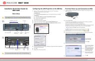
Connecting the <strong>RMX</strong> <strong>1500</strong> to AC Power<br />
<strong>Polycom</strong> <strong>RMX</strong> <strong>1500</strong> <strong>Hardware</strong> <strong>Guide</strong><br />
• Do not connect the green or green-yellow wire to the system single-point<br />
ground screw.<br />
• Only the AC Power cable supplied by <strong>Polycom</strong> should be used.<br />
• The size of the protective earthing conductor should be a minimum of<br />
10AWG.<br />
• The outlet intended for connecting the power cord must be protected with<br />
an external overcurrent protection device either in building or in the rack<br />
with the rating not higher than 20Amp.<br />
• Do not use an Extension cord with the cable.<br />
1 Make sure that the power button is switched OFF on the <strong>RMX</strong> <strong>1500</strong>.<br />
USB Slot<br />
ON/OFF<br />
button<br />
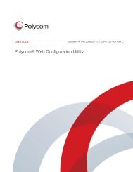
2 Insert the power cable into the power connector on the rear panel of<br />
the <strong>RMX</strong> <strong>1500</strong>.<br />
1-11
Chapter 1-<strong>Hardware</strong> Description<br />
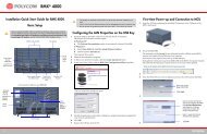
Connecting Cables to the <strong>RMX</strong> <strong>1500</strong><br />
1-12<br />
To connect the cables:<br />
• For the RTM-IP <strong>1500</strong> module:<br />
— Connect the Media cable to LAN 2 port.<br />
(Optional) Connect the LAN cable to LAN 1. For more<br />
information, see <strong>RMX</strong> <strong>1500</strong>/2000/4000 Administrator’s <strong>Guide</strong>,<br />
"LAN Redundancy” on page 14-46.<br />
— Connect the Network cables to the MNG (Signaling) port &<br />
MNGB (Management Network) port.<br />
— (Optional) Connect the Shelf Management cable to the Shelf port.<br />
• For the RTM ISDN <strong>1500</strong> module:<br />
— Connect the E1/T1 cables to their PRI (1-4) ports.<br />
Power Cable<br />
First-time Power-up<br />
E1/T1 PRI<br />
Connection(s)<br />
LAN 2; media, MNG; signaling,<br />
MNGB; management & Shelf<br />
Figure 1-1 <strong>RMX</strong> <strong>1500</strong> Rear Panel View with AC Power and Communication<br />
Cables<br />
The LAN 1, LAN3, LAN4 and Modem ports are not be used and the plastic caps<br />
covering those ports should not be removed.<br />
1 For first entry installation, you must insert the USB key containing the<br />
modified IP addresses in USB slot on the <strong>RMX</strong>’s front panel. For more
<strong>Polycom</strong> <strong>RMX</strong> <strong>1500</strong> <strong>Hardware</strong> <strong>Guide</strong><br />
information see, the <strong>RMX</strong> <strong>1500</strong>/2000/4000 Getting Started <strong>Guide</strong>,<br />
"Procedure 1: First-time Power-up” on page 2-22.<br />
2 Turn ON the power by pressing on the power switch located on the<br />
front panel of the <strong>RMX</strong> <strong>1500</strong>.<br />
The parameters in the lan.cfg file are uploaded from the USB key to<br />
the <strong>RMX</strong>’s memory and applied during the power-up sequence.<br />
System power-up sequence may take up to five minutes.<br />
During the First-time Power-up the red ERROR LED on the <strong>RMX</strong>’s<br />
front panel remains ON until both the Management and IP Network<br />
Services have been defined.<br />
When the <strong>RMX</strong>'s configuration is completed (including the<br />
Management and IP Network Services), and if there are no System<br />
Errors, the green READY LED (on the <strong>RMX</strong>’s front panel) turns ON.<br />
3 Remove the USB key. For more information see, the <strong>RMX</strong> <strong>1500</strong>/2000/<br />
4000 Getting Started <strong>Guide</strong>, "<strong>Hardware</strong> Description", "Procedure 4:<br />
Modifying the Default IP Service and ISDN/PSTN Network Service<br />
Settings” on page 2-26<br />
1-13
Chapter 1-<strong>Hardware</strong> Description<br />
<strong>RMX</strong> <strong>1500</strong> Components<br />
<strong>RMX</strong> <strong>1500</strong> Front Panel<br />
1-14<br />
On the <strong>RMX</strong> <strong>1500</strong>, components are located on both the front and rear of<br />
the MCU as listed in Table 1-6, "<strong>Polycom</strong> <strong>RMX</strong> <strong>1500</strong> Front Panel<br />
Description". For more information see the descriptions of the "<strong>RMX</strong> <strong>1500</strong><br />
Front Panel” on page 1-14 and "<strong>RMX</strong> <strong>1500</strong> Rear Panel” on page 1-16.<br />
The front panel enables access to the <strong>RMX</strong> <strong>1500</strong> using a USB key,<br />
keyboard, mouse and VGA connection.<br />
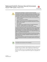
Opening the <strong>RMX</strong> <strong>1500</strong> Front Panel<br />
The <strong>RMX</strong> <strong>1500</strong> has a front panel which can be opened by pressing on the<br />
location shown in the following illustration:
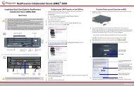
Front Panel Components<br />
Figure 1-2 <strong>RMX</strong> <strong>1500</strong> Front Panel<br />
Table 1-6 <strong>Polycom</strong> <strong>RMX</strong> <strong>1500</strong> Front Panel Description<br />
SLOT/Button/<br />
LED<br />
USB Slot<br />
VGA Slot<br />
Description<br />
<strong>Polycom</strong> <strong>RMX</strong> <strong>1500</strong> <strong>Hardware</strong> <strong>Guide</strong><br />
USB Slot USB key connection, used for First time configuration.<br />
VGA Slot Monitor connection.<br />
Keyboard Slot Keyboard connection.<br />
Mouse Slot Mouse connection.<br />
ON/OFF Button Turn the <strong>RMX</strong> ON or OFF.<br />
READY Led Orange - <strong>RMX</strong> Starting up.<br />
Green - <strong>RMX</strong> ready/online.<br />
IN USE Led Amber - In use, when a conference is active.<br />
ERROR Led Red - Error.<br />
Keyboard Slot<br />
Mouse slot<br />
ON/OFF<br />
button<br />
Front<br />
LEDs<br />
1-15
Chapter 1-<strong>Hardware</strong> Description<br />
<strong>RMX</strong> <strong>1500</strong> Rear Panel<br />
1-16<br />
The <strong>RMX</strong> <strong>1500</strong> rear panel contains the RTM IP <strong>1500</strong> and optionally, the<br />
RTM ISDN <strong>1500</strong>. In addition, the rear panel houses the power supply with<br />
fan & AC inlet, and Serial port.<br />
Power Supply<br />
with built in Fan<br />
RTM IP <strong>1500</strong><br />
RTM ISDN <strong>1500</strong> RTM IP <strong>1500</strong> Serial<br />
Slot<br />
This card contains an Ethernet Switch that manages the network of the<br />
system, routes data between the cards and components of the system and<br />
provides connectivity to external IP networks. It controls and monitors<br />
the system fans and regulates power supply.<br />
The RTM IP <strong>1500</strong> connections include:<br />
• 2 signalling & media ports<br />
• 2 ethernet management ports<br />
• Shelf (Manager) port<br />
• Modem<br />
• 1 Serial port<br />
The LAN 1, LAN3, LAN4 and Modem ports are not be used and the plastic caps<br />
covering those ports should not be removed.
LAN 1-2<br />
Ports<br />
Signaling & Management<br />
Ports<br />
Shelf<br />
connection<br />
Figure 1-3 <strong>RMX</strong> <strong>1500</strong> RTM IP Rear Panel Layout<br />
The following items appear on the <strong>RMX</strong> <strong>1500</strong> rear panel:<br />
<strong>Polycom</strong> <strong>RMX</strong> <strong>1500</strong> <strong>Hardware</strong> <strong>Guide</strong><br />
NA Modem Serial<br />
Port Port<br />
LAN3, LAN 4 and the Serial<br />
ports are only for debugging and not<br />
for customer use<br />
Main RS 232<br />
Switch<br />
Standby button<br />
Table 1-7 <strong>RMX</strong> <strong>1500</strong> Rear Panel - RTM IP <strong>1500</strong> Component Description<br />
Item Description<br />
LAN 1 port Redundant LAN (Media) Connection. 1 Media IP address<br />
is available. Always use LAN2 if using a single LAN<br />
network connection. For more information on Lan<br />
Redundancy, see the <strong>RMX</strong> <strong>1500</strong>/2000/4000<br />
Administrator’s <strong>Guide</strong>, "LAN Redundancy” on page 14-<br />
92.<br />
LAN 2 port LAN (Media) Connection. 1 Media IP address is available.<br />
MNG port Signaling connection.<br />
MNGB Management connection for Web Client and <strong>RMX</strong><br />
Manager.<br />
LAN 3/4 ports Not Available (NA).<br />
Note: LAN 3/4 are covered with a plastic cap that should<br />
not be removed.<br />
Shelf (Manager)<br />
port<br />
(Optional) Shelf Manager connection.<br />
Modem port Internal IP connection, for debugging purposes only.<br />
Serial (RS 232)<br />
port<br />
For debugging purposes only. Enables print-outs of<br />
various LOGs from RTM IP <strong>1500</strong> and Card Manager.<br />
1-17
Chapter 1-<strong>Hardware</strong> Description<br />
1-18<br />
Table 1-7 <strong>RMX</strong> <strong>1500</strong> Rear Panel - RTM IP <strong>1500</strong> Component Description<br />
Item Description<br />
MAIN/RTM Selection of the connection type for the RS-232 Port.<br />
When the switch is up - the serial port connects to the<br />
MPMx card.<br />
When the switch is down, connects to the RTM IP.<br />
Standby button Toggle button. Use this button to either perform<br />
Diagnostics or Software Recovery on the <strong>RMX</strong>.<br />
Short press (2 seconds) - MPMx Diagnostics.<br />
Long press - (10 seconds) Media and RTM IP <strong>1500</strong><br />
Software Recovery.<br />
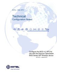
RTM ISDN <strong>1500</strong><br />
The RTM ISDN <strong>1500</strong> connects directly to the built-in MPMx. The RTM<br />
ISDN card routes data between the MPMx card and components of the<br />
system, converts ISDN T1/E1 media to IP packets and provides<br />
connectivity to external ISDN networks.<br />
The RTM ISDN card is installed on the rear panel of the <strong>RMX</strong> interfaces<br />
between the <strong>RMX</strong> unit and the ISDN/PSTN switch.<br />
With the <strong>RMX</strong> <strong>1500</strong>, you can either have a dedicated E1 or T1 Type Network<br />
Service. It is not possible to have a mixed E1 and T1 ISDN Network Service.<br />
The RTM ISDN card contains four connections to which up to four E1 or<br />
T1 PRI lines can be connected as shown in Figure 1-4.<br />
4 E1/T1 connections<br />
Figure 1-4 <strong>RMX</strong> <strong>1500</strong> RTM ISDN Rear Panel Layout
<strong>Polycom</strong> <strong>RMX</strong> <strong>1500</strong> <strong>Hardware</strong> <strong>Guide</strong><br />
The RTM ISDN card supports up to 120 audio participants, regardless of<br />
whether the spans are E1 or T1.<br />
1-19
Chapter 1-<strong>Hardware</strong> Description<br />
1-20<br />
ISDN/PSTN Clock Source<br />
<strong>RMX</strong> <strong>1500</strong> Power Supply<br />
Each RTM ISDN <strong>1500</strong> has its own primary and secondary clock source.<br />
The first span to synchronize becomes the primary clock source and the<br />
second span to synchronize becomes the secondary clock source. This<br />
clock is used to synchronize ISDN spans only (it is not the system clock).<br />
A single clock source triggers an alarm that can be turned off by setting<br />
the appropriate flag in the system configuration.<br />
Subject to availability on the <strong>RMX</strong> <strong>1500</strong> there are two types of power<br />
supplies (Power-One & Astec), both are identical in their functionality.<br />
Power Supply LEDs<br />
On the <strong>RMX</strong> <strong>1500</strong> there are three LEDs that indicate the power status.<br />
Table 1-8 <strong>Polycom</strong> <strong>RMX</strong> <strong>1500</strong> Power Supply LEDs<br />
Power Supply LED Description<br />
OK DC power indication to internal components of the <strong>RMX</strong>:<br />
Green - DC Power Good.<br />
(Alarm symbol)<br />
Power supply failure Indication:<br />
Amber - Power Supply Failure.<br />
AC/~ (symbol) Main power supply indication (Voltage In):<br />
Green - Voltage Input > 85 VAC.
<strong>RMX</strong> <strong>1500</strong> LEDs<br />
<strong>Polycom</strong> <strong>RMX</strong> <strong>1500</strong> <strong>Hardware</strong> <strong>Guide</strong><br />
The <strong>RMX</strong> includes LEDs located on the front panel and rear panel. In the<br />
front panel, the LEDs reflect the state of the components. The LEDs on the<br />
rear panel indicate the state of the external connections and the status of<br />
the RTM IP card.<br />
<strong>RMX</strong> <strong>1500</strong> Front Panel LEDs<br />
The following items appear on the <strong>RMX</strong> <strong>1500</strong> front panel:<br />
Table 1-9 <strong>RMX</strong> <strong>1500</strong> Front Panel LED’s<br />
Component LED ID LED Color Indication<br />
Front Panel ERROR Red ON - Major system error. In case<br />
of an active alarm this light is ON,<br />
and the READY-green is OFF.<br />
OFF - Normal.<br />
Flashes - During system startup.<br />
READY Green ON - CPU card has successfully<br />
completed startup. This light turns<br />
green after completing the entire<br />
system configuration.<br />
OFF - Turns OFF when the<br />
ERROR red LED is activated.<br />
Flashes - During system startup.<br />
IN USE Amber ON - At least one endpoint is<br />
connected to the system.<br />
Flashes - During system startup.<br />
1-21
Chapter 1-<strong>Hardware</strong> Description<br />
<strong>RMX</strong> <strong>1500</strong> Rear Panel LEDs<br />
1-22<br />
RTM IP <strong>1500</strong> LEDs<br />
The following LEDs appear on the RTM IP <strong>1500</strong>:<br />
Table 1-10 RTM IP <strong>1500</strong> LEDs<br />
Component<br />
LED<br />
Name<br />
LED Color Indication<br />
LAN LEDs (1-2) LNK Green ON with an active network<br />
connection, flickers with Packet<br />
activity.<br />
1 Gb Amber ON with a 1Gb online<br />
connection, flickers with Packet<br />
activity.<br />
MNG LED LNK Green ON with an active network<br />
connection, flickers with Packet<br />
activity.<br />
1 Gb Amber ON with a 1Gb online<br />
connection, flickers with Packet<br />
activity.<br />
MNG B LED LNK Green ON with an active network<br />
connection, flickers with Packet<br />
activity.<br />
1 Gb Amber ON with a 1Gb online<br />
connection, flickers with Packet<br />
activity.<br />
Shelf LED LNK Green ON with an active network<br />
connection, flickers with Packet<br />
activity.<br />
100 Amber ON when the active network is<br />
10/100Mb, flickers with Packet<br />
activity.
Table 1-10 RTM IP <strong>1500</strong> LEDs (Continued)<br />
Component<br />
<strong>Polycom</strong> <strong>RMX</strong> <strong>1500</strong> <strong>Hardware</strong> <strong>Guide</strong><br />
Modem LNK Green ON with an active network<br />
connection, flickers with activity.<br />
Additional LEDs<br />
(4)<br />
LED<br />
Name<br />
LED Color Indication<br />
Amber ON when the active network is<br />
10/100Mb, flickers with activity.<br />
ERR Red ON - Major error on RTM IP<br />
<strong>1500</strong>.<br />
Flashes - During system<br />
startup.<br />
ACT Red ON - Packet flow to and from<br />
the MCU chassis.<br />
Flashes - During system<br />
startup.<br />
STBY Green ON - CPU & System are in a<br />
standby (OFF) mode.<br />
RDY Green ON - RTM IP <strong>1500</strong> has<br />
successfully completed startup.<br />
Flashes - During system<br />
startup.<br />
1-23
Chapter 1-<strong>Hardware</strong> Description<br />
1-24<br />
RTM ISDN <strong>1500</strong> LEDS<br />
The following LEDs appear on the RTM ISDN:<br />
Table 1-11 RTM ISDN <strong>1500</strong> LEDs<br />
Function Name LED Color Indication<br />
PRI (1-4) LEDs OFF Span x not in use.<br />
Power Supply LEDs<br />
Green Span x is OK.<br />
Red Span x red alarm (LOS - Loss of Signal)<br />
The following items appear on the rear panel power supply:<br />
Table 1-12 Power Supply LED’s<br />
Component LED ID LED Color Indication<br />
Power Statuses OK Green OK.<br />
Alarm Amber PS Fail - Problem with power<br />
supply. This amber LED is driven<br />
by internal circuitry and will<br />
illuminate when a power rail has<br />
failed.<br />
AC Green When the power cable is pluggedin,<br />
the AC LED becomes lit.
Component Installation &<br />
Replacement<br />
2<br />
On the <strong>RMX</strong> <strong>1500</strong> you can install and replace the RTM ISDN <strong>1500</strong> card.<br />
For more information see, "Installing the RTM ISDN <strong>1500</strong> Card” on<br />
page 2-2.<br />
Before installing a parts:<br />
• Make sure you have the correct replacement part on hand.<br />
• Make sure you are using proper ESD equipment, to prevent damage<br />
to the system.<br />
Warning!<br />
• All maintenance tasks are to be performed by qualified, authorized personnel.<br />
• Use only replacement parts supplied by your dealer.<br />
• Follow all procedures. Do not skip any steps.
Chapter 2- Component Installation & Replacement<br />
Installing the RTM ISDN <strong>1500</strong> Card<br />
2-2<br />
Prior to adding the RTM ISDN <strong>1500</strong> card you must have your ISDN<br />
product license available. For more information see, <strong>RMX</strong> <strong>1500</strong>/2000/<br />
Getting Started <strong>Guide</strong>, "Procedure 2: Product Registration” on page 2-23.<br />
1 Ensure that the power switch on the <strong>RMX</strong> <strong>1500</strong> is turned OFF (O).<br />
2 Loosen the captive screws that fasten the card to the MCU.<br />
3 Slide in the RTM ISDN <strong>1500</strong> card.<br />
4 Insert the card into the slot and tighten the captive screws on each<br />
side of the rear panel of the card, securing the RTM ISDN card to<br />
<strong>RMX</strong>.
<strong>Polycom</strong> <strong>RMX</strong> <strong>1500</strong> <strong>Hardware</strong> <strong>Guide</strong><br />
5 Connect the PRI cables.<br />
4 E1/T1 connections<br />
6 Turn ON the <strong>RMX</strong> <strong>1500</strong>.<br />
7 Login on to the <strong>RMX</strong> Web Client.<br />
a Update your license. For more information see, <strong>RMX</strong> <strong>1500</strong>/2000/<br />
Getting Started <strong>Guide</strong>, Chapter 2, “Procedure 2: Product Registration”<br />
on page 2-23.<br />
b In the ISDN/PSTN Network Services define a New ISDN Network<br />
Service. For more information see, <strong>RMX</strong> <strong>1500</strong>/2000/4000<br />
Administrator’s <strong>Guide</strong>, Chapter 14, “Adding/Modifying ISDN/PSTN<br />
Network Services” on page 14-54.<br />
2-3
Chapter 2- Component Installation & Replacement<br />
Component Replacement<br />
2-4<br />
The <strong>RMX</strong> <strong>1500</strong> is designed with ease of maintenance in mind. Most<br />
components are swappable and are accessible directly via the front panel<br />
or the rear panel.<br />
The following component can be replaced when it is faulty:<br />
The RTM-IP <strong>1500</strong> and Power Supply are not field replaceable.<br />
• RTM ISDN <strong>1500</strong>, see "Replacing the RTM ISDN <strong>1500</strong>” on page 2-5.<br />
Before replacing a part:<br />
• Make sure you have the correct replacement part on hand.<br />
• Make sure you are using proper ESD equipment, to prevent damage<br />
to the system.
<strong>Polycom</strong> <strong>RMX</strong> <strong>1500</strong> <strong>Hardware</strong> <strong>Guide</strong><br />
Replacing the RTM ISDN <strong>1500</strong><br />
1 Ensure that the power switch on the <strong>RMX</strong> <strong>1500</strong> is turned OFF (O).<br />
2 Remove the PRI cables.<br />
3 Loosen the captive screws that fasten the card to the MCU.<br />
4 Remove the RTM ISDN card and pull the RTM ISDN card out of its<br />
slot in the backplane.<br />
5 Carefully slide the RTM ISDN card out through the rear panel.<br />
6 Slide in the replacement RTM ISDN card into it’s slot.<br />
7 Tighten the captive screws on each side of the rear panel of the card,<br />
securing the RTM ISDN card to <strong>RMX</strong>.<br />
8 Connect the PRI cables.<br />
9 Turn ON the <strong>RMX</strong> <strong>1500</strong>.<br />
2-5