Aerocomm AC4868.pdf - HEAnet Mirror Service
Aerocomm AC4868.pdf - HEAnet Mirror Service
Aerocomm AC4868.pdf - HEAnet Mirror Service

You also want an ePaper? Increase the reach of your titles
YUMPU automatically turns print PDFs into web optimized ePapers that Google loves.
PIN DEFINITIONS<br />
www.aerocomm.com<br />
SPECIFICATIONS<br />
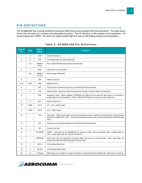
The AC4868-250 has a simple interface that allows OEM Host communications with the transceiver. The table below<br />
shows the connector pin numbers and associated functions. The I/O direction is with respect to the transceiver. All<br />
inputs/outputs are 3.3VDC. All inputs are weakly pulled High and may be left floating during normal operation.<br />
Module<br />
Pin<br />
Type<br />
Signal<br />
Name<br />
1 O GO0 Generic Output pin<br />
Table 2: AC4868-250 Pin Definitions<br />
2 O TXD Transmitted data out of the transceiver<br />
I/O RS485 A<br />
(True)<br />
Non-inverted RS-485 representation of serial data<br />
3 I RXD Data input to the transceiver<br />
I/O RS485 B<br />
(Invert)<br />
<strong>Mirror</strong> image of RS-485 A<br />
4 I GI0 Generic Input pin<br />
5, 16 GND GND Signal Ground<br />
Function<br />
6 N/C This pin has an internal connection and should be left disconnected.<br />
7 O CTS Clear to Send – Active Low when the transceiver is ready to accept data for transmission.<br />
8 I RTS Request to Send – When enabled in EEPROM, the OEM Host can take this High when it is not ready to<br />
accept data from the transceiver. NOTE: Keeping RTS High for too long can cause data loss.<br />
9 O GO1 Generic Output pin<br />
10 PWR VCC1 3.3 – 5.5V, ±50mV ripple<br />
11 PWR VCC2 3.3V, ±50mV ripple<br />
12 I Test Test Mode – When pulled logic Low and then applying power or resetting, the transceiver’s serial interface<br />
is forced to a 9600, 8-N-1 rate. To exit, the transceiver must be reset or power-cycled with Test Mode logic<br />
High.<br />
13 N/C This pin has an internal connection and should be left disconnected.<br />
14 I GI1 Generic Input pin<br />
15 I UP_RESET RESET – Controlled by the AC4868-250 for power-on reset if left unconnected. After a stable power-on<br />
reset, a logic High pulse will reset the transceiver.<br />
17 I CMD/Data When logic Low, the transceiver interprets OEM Host data as command data. When logic High, the<br />
transceiver interprets OEM Host data as transmit data.<br />
18 I AD In 10 bit Analog Data Input<br />
19 O DA_Out 10 bit Analog Data Output<br />
20 O In_Range When logic Low, a Client is in range of a Server on same Channel and System ID. Always low on a Server.<br />
3