615611 Electronics Workshop 2 Manual - Thames & Kosmos
615611 Electronics Workshop 2 Manual - Thames & Kosmos
615611 Electronics Workshop 2 Manual - Thames & Kosmos

Create successful ePaper yourself
Turn your PDF publications into a flip-book with our unique Google optimized e-Paper software.
Assembly Instructions<br />
The Consoles<br />
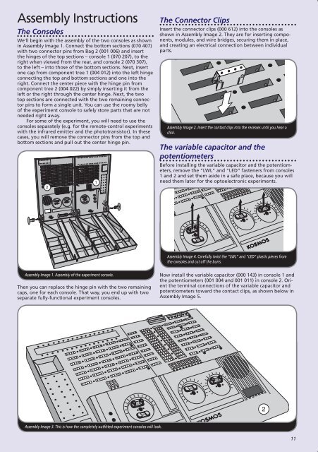
We’ll begin with the assembly of the two consoles as shown<br />
in Assembly Image 1 . Connect the bottom sections (070 407)<br />
with two connector pins from Bag 2 (001 006) and insert<br />
the hinges of the top sections – console 1 (070 207), to the<br />
right when viewed from the rear, and console 2 (070 307),<br />
to the left – into those of the bottom sections . Next, insert<br />
one cap from component tree 1 (004 012) into the left hinge<br />
connecting the top and bottom sections and one into the<br />
right . Connect the center piece with the hinge pin from<br />
component tree 2 (004 022) by simply inserting it from the<br />
left or the right through the center hinge . Next, the two<br />
top sections are connected with the two remaining connector<br />
pins to form a single unit . You can use the roomy belly<br />
of the experiment console to safely store parts that are not<br />
needed right away .<br />
For some of the experiment, you will need to use the<br />
consoles separately (e .g . for the remote-control experiments<br />
with the infrared emitter and the phototransistor) . In these<br />
cases, you will remove the connector pins from the top and<br />
bottom sections and pull out the center hinge pin .<br />
2<br />
Assembly Image 1. Assembly of the experiment console.<br />
Then you can replace the hinge pin with the two remaining<br />
caps, one for each console . That way, you end up with two<br />
separate fully-functional experiment consoles .<br />
Assembly Image 3. This is how the completely outfitted experiment consoles will look.<br />
1<br />
LED<br />
LWL<br />
OSMOS<br />
The Connector Clips<br />
Insert the connector clips (000 612) into the consoles as<br />
shown in Assembly Image 2 . They are for inserting components,<br />
modules, and wire bridges, securing them in place,<br />
and creating an electrical connection between individual<br />
parts .<br />
Assembly Image 2. Insert the contact clips into the recesses until you hear a<br />
click.<br />
The variable capacitor and the<br />
potentiometers<br />
Before installing the variable capacitor and the potentiometers,<br />
remove the “LWL” and “LED” fasteners from consoles<br />
1 and 2 and set them aside in a safe place, because you will<br />
need them later for the optoelectronic experiments .<br />
4000.1<br />
Now install the variable capacitor (000 143) in console 1 and<br />
the potentiometers (001 004 and 001 011) in console 2 . Orient<br />
the terminal connections of the variable capacitor and<br />
potentiometers toward the contact clips, as shown below in<br />
Assembly Image 5 .<br />
1<br />
LED<br />
LWL<br />
LWL<br />
KOSMOS<br />
LED<br />
KOSMOS<br />
KOSMOS<br />
Assembly Image 4. Carefully twist the “LWL” and “LED” plastic pieces from<br />
the consoles and cut off the burrs.<br />
LWL<br />
LED<br />
2<br />
11