615611 Electronics Workshop 2 Manual - Thames & Kosmos
615611 Electronics Workshop 2 Manual - Thames & Kosmos
615611 Electronics Workshop 2 Manual - Thames & Kosmos

Create successful ePaper yourself
Turn your PDF publications into a flip-book with our unique Google optimized e-Paper software.
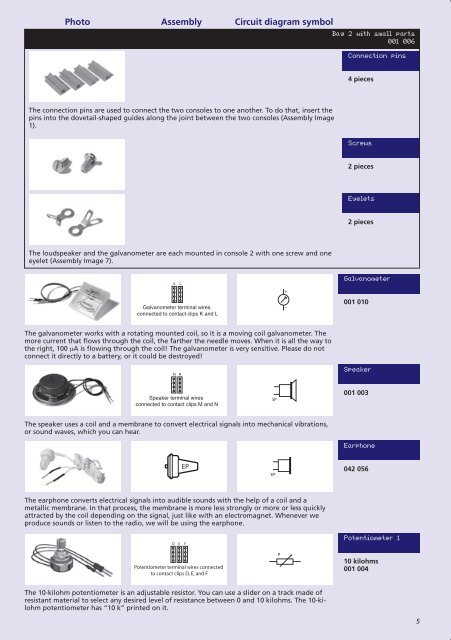
The connection pins are used to connect the two consoles to one another . To do that, insert the<br />
pins into the dovetail-shaped guides along the joint between the two consoles (Assembly Image<br />
1) .<br />
The loudspeaker and the galvanometer are each mounted in console 2 with one screw and one<br />
eyelet (Assembly Image 7) .<br />
The galvanometer works with a rotating mounted coil, so it is a moving coil galvanometer . The<br />
C C<br />
more current that flows through the coil, the farther the needle moves . When HS it is all C HSC<br />
the way to<br />
the right, 100 µA is flowing through the coil! The galvanometer is very sensitive . Please do not<br />
connect it directly to a battery, or it could be destroyed!<br />
M N<br />
The speaker uses a coil and a membrane to convert TF<br />
D<br />
C<br />
TF electrical signals into mechanical vibrations,<br />
R C<br />
Ge<br />
R<br />
Ge<br />
TF<br />
or sound waves, which you can hear .<br />
TF<br />
EP<br />
A<br />
R<br />
E C<br />
Speaker<br />
Speaker<br />
terminal<br />
terminal<br />
wires<br />
wires<br />
connected<br />
connected<br />
to<br />
to<br />
contact<br />
contact<br />
clips<br />
clips<br />
M<br />
M<br />
and<br />
and<br />
N<br />
N<br />
K K<br />
SP E<br />
SP E<br />
+<br />
C<br />
C<br />
EP TFEP<br />
TF<br />
E<br />
E<br />
C<br />
C<br />
V C<br />
+<br />
C<br />
+<br />
A AMP A AMP EP EP<br />
–<br />
E<br />
E<br />
E<br />
TF<br />
TF<br />
A<br />
D E F<br />
The earphone converts electrical signals into audible F sounds with the help of a coil and a<br />
metallic membrane D<br />
V<br />
+ . In that process, the membrane is more less strongly or more V P or less quickly<br />
Ge +<br />
Ge<br />
+ Ta Ta<br />
attracted by the C<br />
+<br />
C coil depending on the signal, just like with an electromagnet . Whenever A AMP we<br />
A<br />
produce sounds K or listen to the radio, Potentiometer we will terminal be using wires connected the earphone . AMP –<br />
–<br />
to contact clips D, E, and F<br />
E<br />
E<br />
LED LED 1 1<br />
A A<br />
A<br />
A<br />
K<br />
K<br />
D<br />
D<br />
Ge<br />
Ge<br />
LED<br />
B C<br />
p<br />
n<br />
p<br />
Photo E E E E<br />
Assembly Circuit diagram symbol<br />
B C<br />
n<br />
p<br />
n<br />
E E<br />
B C<br />
p<br />
n<br />
p<br />
B C<br />
n<br />
p<br />
n<br />
E E<br />
A K A K<br />
IR-LED IR-LED<br />
Speaker terminal wires<br />
connected to contact clips M and N<br />
AMP<br />
E<br />
–<br />
R<br />
A M N<br />
C CK<br />
+<br />
+<br />
A<br />
Ta<br />
Ta<br />
A DA E KF<br />
D E FK<br />
A<br />
DSi<br />
K<br />
E E E E<br />
V<br />
+<br />
A A K K<br />
Potentiometer<br />
Potentiometer<br />
terminal<br />
terminal<br />
wires<br />
wires<br />
connected<br />
connected<br />
to<br />
to<br />
contact<br />
contact<br />
clips D, E, and F<br />
B Bclips C D, CE,<br />
and F<br />
–<br />
DGe DGe M N<br />
A A K K<br />
E<br />
AMP<br />
AMP<br />
–<br />
E<br />
–<br />
K L<br />
R<br />
Galvanometer Galvanometer terminal wires terminal wires<br />
connected to connected contact clips to contact K and Lclips<br />
K and L<br />
LED 3<br />
–<br />
LED LED 2 2<br />
A BA CB<br />
C<br />
SP<br />
+<br />
R R<br />
Bag 2 with small parts<br />
001 006<br />
Connection pins<br />
4 pieces<br />
Screws<br />
2 pieces<br />
Eyelets<br />
2 pieces<br />
Galvanometer<br />
001 010<br />
– Variable capacitor Variable terminal capacitor wiresterminal<br />
wires<br />
B<br />
connected to connected contact clips to A, contact B, and clips C A, B, and C<br />
+ +<br />
LED C<br />
A A<br />
C<br />
D<br />
C<br />
P<br />
P LED LED<br />
K K<br />
C C<br />
B<br />
A<br />
B<br />
K<br />
D<br />
Si<br />
E<br />
T<br />
E<br />
T<br />
The 10-kilohm potentiometer is an adjustable resistor . You can use a slider on a track made of<br />
Ta<br />
resistant material to select any desired level of resistance between 0 and 10 kilohms . The 10-ki-<br />
EP<br />
lohm potentiometer EP has “10 k” printed on it .<br />
A<br />
A<br />
DSi<br />
A<br />
DSi<br />
A<br />
K<br />
K<br />
V<br />
V<br />
+<br />
+<br />
K L<br />
LED 3<br />
A K<br />
220 kΩ<br />
A<br />
K<br />
NTC<br />
+<br />
–<br />
LED<br />
A A C C<br />
A<br />
A<br />
220 kΩ<br />
A<br />
K<br />
D<br />
NTC<br />
6<br />
1<br />
DGe DGe<br />
A A K<br />
K<br />
A B C<br />
2<br />
EP<br />
4 3<br />
6 1<br />
B<br />
A B C<br />
Speaker<br />
001 EP003<br />
D ED FE<br />
F<br />
+<br />
+ HS HS<br />
X<br />
Potentiometer X terminal terminal wires wires connected<br />
LED to contact to 3 –<br />
3<br />
contact – clips clips D, E, D, and E, and F F<br />
A K<br />
Earphone<br />
042 056<br />
Speaker Speaker terminal terminal wires wires B<br />
connected to contact to contact clips clips M and M and N N<br />
1<br />
2<br />
5<br />
6<br />
7<br />
A K<br />
IR-LED<br />
B C<br />
p<br />
LED p<br />
LED<br />
3<br />
3 n<br />
p<br />
n<br />
p<br />
A<br />
AE K<br />
E K DSi E DSi<br />
A A<br />
A<br />
A<br />
K<br />
K<br />
IR-LED<br />
IR-LED<br />
B C<br />
B 324 C<br />
p<br />
Potentiometer n p<br />
1<br />
K K<br />
1<br />
2<br />
3<br />
4<br />
14 14<br />
13 13<br />
12 12<br />
11 11<br />
10 10<br />
9<br />
8<br />
IN<br />
PCO<br />
+<br />
+<br />
A C A C<br />
M NM<br />
N<br />
+ HS<br />
X<br />
EP –<br />
AMP<br />
10 kilohms<br />
001 004<br />
OUT<br />
PLL<br />
VCO<br />
E<br />
AMP<br />
–<br />
+<br />
TF TF<br />
E E C C<br />
E<br />
–<br />
p n<br />
p<br />
E E<br />
E E<br />
–<br />
A<br />
A<br />
–<br />
VCI<br />
G HG IH<br />
I<br />
R<br />
5<br />
V<br />
V<br />
Potentiometer terminal terminal wires wires connected<br />
to contact to contact clips clips G, H, G, and H, and I I<br />
+<br />
1<br />
1<br />
2<br />
2<br />
3<br />
3<br />
4<br />
4<br />
5<br />
5<br />
6<br />
6<br />
7<br />
7<br />
324 324<br />
+<br />
14<br />
14<br />
13<br />
13<br />
12<br />
12<br />
11<br />
11<br />
10<br />
10<br />
9<br />
9<br />
8<br />
8<br />
IN<br />
IN<br />
PCO<br />
PCO<br />
E<br />
6<br />
C<br />
E<br />
4 3<br />
+<br />
+<br />
2<br />
B<br />
B<br />
A<br />
OUT<br />
OUT<br />
PLL<br />
PLL<br />
VCO<br />
VCO<br />
E<br />
D Ge<br />
1<br />
C<br />
E<br />
K<br />
6<br />
4<br />
–<br />
32<br />
VCI<br />
VCI<br />
–<br />
EP<br />
R<br />
R<br />
A<br />
D Ge<br />
10 mF<br />
100 nF<br />
220 kΩ<br />
K<br />
Spe<br />
connected<br />
4<br />
3<br />
AMP<br />
Potent<br />
connected