615611 Electronics Workshop 2 Manual - Thames & Kosmos
615611 Electronics Workshop 2 Manual - Thames & Kosmos
615611 Electronics Workshop 2 Manual - Thames & Kosmos

You also want an ePaper? Increase the reach of your titles
YUMPU automatically turns print PDFs into web optimized ePapers that Google loves.
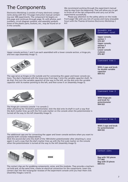
The Components<br />
<strong>Electronics</strong> <strong>Workshop</strong> 2 consists of many electronic components<br />
along with this 172-page instruction manual containing<br />
over 300 experiments . The component list begins on<br />
this page and continues through page 10, with photos, part<br />
numbers, circuit diagram symbols, and assembly symbols .<br />
Some of the plastic parts, buttons, etc ., may be found on or<br />
in the consoles .<br />
Upper console sections 1 and 2 are each assembled with a lower console section, a hinge pin,<br />
and two caps (Assembly Image 1) .<br />
A<br />
K<br />
operate EP both consoles independently .<br />
Ta<br />
A<br />
R<br />
LED<br />
K<br />
C<br />
G H I<br />
The contact clips are for grabbing components, wires, and the modules . They provide a mechani-<br />
E<br />
C<br />
V<br />
+<br />
the dial’s marker +<br />
C lines up with the first scale marker on the console when the potentiometer is<br />
A<br />
turned all the way to the left (Assembly Image 5) .<br />
AMP<br />
–<br />
E<br />
D<br />
Ge<br />
A C<br />
Speaker terminal wires<br />
connected to contact clips M and N<br />
AMP<br />
E<br />
–<br />
M N<br />
TF<br />
E C<br />
A<br />
D E F<br />
V<br />
+<br />
Potentiometer terminal wires connected<br />
to contact clips D, E, and F<br />
The additional caps are for connecting the upper and lower console sections when you want to<br />
Stick this second dial onto the shaft of the 100-kilohm potentiometer after attaching it, once<br />
again in such a way that the dial’s marker lines up with the first scale marker on the console<br />
when the potentiometer is turned all the way to the left (Assembly Image 5) . A<br />
DSi<br />
A K<br />
Potentiometer terminal wires connected<br />
to contact clips G, H, and I<br />
We recommend working through the experiment manual<br />
step by step from the beginning . That will allow you to get<br />
to know all of the lab components and carry out all the<br />
experiments successfully .<br />
Please pay attention to the safety advice on the inside<br />
front page! We wish you lots of success and many enjoyable<br />
hours with the <strong>Thames</strong> & <strong>Kosmos</strong> <strong>Electronics</strong> <strong>Workshop</strong> 2<br />
kit!<br />
The caps serve as hinges on the outside and for connecting the upper and lower console sections<br />
. The dial is fastened with the long screw from bag 1 onto the variable capacitor shaft . To<br />
do that, first turn the variable capacitor all the way to the left, set the dial onto the variable<br />
capacitor with its marker pointing to the left, and then screw it on (Assembly Image 5) .<br />
The hinge pin connects console 1 to console 2 .<br />
After attaching the 10-kilohm potentiometer, stick the dial onto its shaft in such a way that<br />
cal hold and, at the same time, create an electrical connection for the components . Insert the<br />
B T<br />
contact clips into the rectangular recesses of the experiment console until you hear them click<br />
(Assembly Images 2 and 3) .<br />
SP<br />
P<br />
K<br />
C<br />
E<br />
D<br />
Si<br />
TF<br />
Assembly and<br />
Experiment panel<br />
Upper console,<br />
section 1<br />
070 207<br />
Upper console,<br />
section 2<br />
070 307<br />
Lower console<br />
2 pieces<br />
070 407<br />
Component tree 1<br />
With 2 caps and knob<br />
for double variable<br />
capacitor<br />
004 012<br />
Component tree – 2<br />
7<br />
8<br />
LED 3<br />
A K<br />
6<br />
9<br />
5<br />
10<br />
Contact clips<br />
A K<br />
IR-LED<br />
B C<br />
p<br />
n<br />
p<br />
E E<br />
With 2 caps and knob<br />
for potentiometer 324<br />
004 032<br />
IN<br />
PCO<br />
+<br />
+<br />
+<br />
HS<br />
Component tree 3<br />
4<br />
11<br />
–<br />
3<br />
12<br />
2<br />
13<br />
Bag with 102 pieces<br />
771 860<br />
–<br />
Bag with 33 pieces<br />
000 612<br />
+<br />
X<br />
With hinge pin<br />
and knob for<br />
potentiometer<br />
004 022<br />
OUT<br />
PLL<br />
VCO<br />
NTC<br />
–<br />
G H I<br />
VCI<br />
R<br />
1<br />
14<br />
3