615611 Electronics Workshop 2 Manual - Thames & Kosmos
615611 Electronics Workshop 2 Manual - Thames & Kosmos
615611 Electronics Workshop 2 Manual - Thames & Kosmos

Create successful ePaper yourself
Turn your PDF publications into a flip-book with our unique Google optimized e-Paper software.
D2<br />
D2<br />
D3<br />
D3<br />
GND<br />
C<br />
p<br />
n<br />
p<br />
E<br />
GND<br />
Digit<br />
Digit<br />
PWM Uin<br />
D0 Din<br />
D1 Beep<br />
D2 Start<br />
D3 Reset<br />
100 nF<br />
220 kΩ<br />
100 nF<br />
220 kΩ<br />
“<strong>Electronics</strong> <strong>Workshop</strong> Galvanometer 2” manual terminal wires<br />
connected to + contact clips K and L<br />
10 µF<br />
K<br />
10 µF<br />
A<br />
6<br />
1<br />
10 µF<br />
220 kΩ<br />
100 nF<br />
10 µF<br />
220 kΩ<br />
2<br />
C E<br />
64<br />
13<br />
Variable capacitor terminal wires<br />
6<br />
2<br />
1<br />
6<br />
1<br />
2<br />
2<br />
64<br />
4 3<br />
3<br />
C E C<br />
B<br />
A<br />
E<br />
220 kΩ<br />
1<br />
6<br />
2<br />
Variable A capacitor C DGe terminal wires<br />
A K<br />
connected to contact clips A, B, and C<br />
D Ge<br />
TF B<br />
E A CK<br />
B<br />
AMP<br />
K<br />
E<br />
–<br />
4<br />
A<br />
3<br />
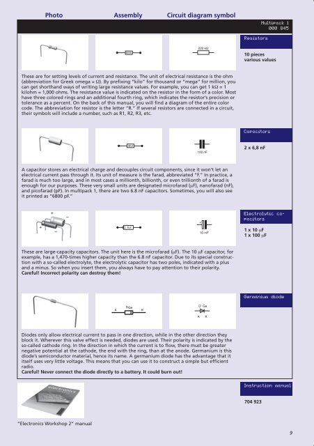
Resistors<br />
K A<br />
+ –<br />
M<br />
U V<br />
S<br />
+<br />
+<br />
T<br />
–<br />
O<br />
10 mF<br />
U<br />
P<br />
M<br />
R<br />
10 kΩ<br />
UV<br />
10 pieces<br />
various values<br />
C E<br />
C<br />
C<br />
n<br />
p<br />
n<br />
E<br />
A K<br />
These are for setting levels of current and resistance . The unit of electrical resistance is the ohm<br />
B<br />
(abbreviation for Greek omega = Ω) . By prefixing CDS“kilo”<br />
for thousand or “mega” for million, you<br />
can get shorthand ways of writing large resistance NTC values C.<br />
For example, you can get E1<br />
kΩ = 1<br />
kilohm = 1,000 ohms . The resistance value is indicated on the resistor in the form of a color . Most<br />
+<br />
have three colored rings CDS and an additional fourth ring, B which indicates the resistor’s Kprecision<br />
A or K<br />
tolerance as a percent . On the back of this manual, A K you will find a diagram of the entire color<br />
E<br />
10 mF<br />
code . The abbreviation for resistor is the letter “R .” If several resistors are connected in a circuit,<br />
A<br />
O<br />
9 V<br />
NTC<br />
P<br />
100 nF + –<br />
OR<br />
10 kΩ<br />
P<br />
10<br />
their symbols will include a number, such as R1, KR2,<br />
AR3,<br />
etc .<br />
A K<br />
220 C kΩ E<br />
A<br />
K A<br />
CDS<br />
C<br />
B<br />
C<br />
B<br />
C<br />
A K<br />
+<br />
M N<br />
+<br />
+ NTC<br />
PHT –<br />
Capacitors M<br />
U V<br />
NTC<br />
NTC<br />
A<br />
DGe<br />
K<br />
K<br />
B<br />
A<br />
E<br />
E<br />
D Ge<br />
A K<br />
E<br />
10 mF<br />
10 mF<br />
2 x 6,8 nF<br />
100 Speaker nF terminal wires<br />
SP<br />
connected to contact clips M and N<br />
C<br />
A K+<br />
–<br />
E C<br />
K L<br />
A B C<br />
A C<br />
C<br />
C<br />
A capacitor stores an electrical + charge and decouples circuit components, since it won’t let TFan<br />
electrical current pass through it . Its unit of measure is the farad, abbreviated B<br />
B “F .” In practice, a<br />
E C<br />
220 kΩ<br />
nometer terminal farad wires is much too large, – and in most cases a millionth, billionth, or even trillionth of a farad is<br />
NTC Variable NTCcapacitor<br />
terminal wires<br />
ed to contact enough clips K and for L our purposes . These very small units are designated E microfarad B E<br />
connected to contact clips A, B, and C<br />
(µF), Knanofarad<br />
A (nF),<br />
100 nF<br />
100 nF<br />
and picofarad (pF) . In multipack 1, there are two 6 .8 nF capacitors . Sometimes, you will also see<br />
S<br />
O<br />
K<br />
C<br />
A<br />
P<br />
E<br />
PHT T<br />
R<br />
10 TFkΩ<br />
P<br />
it printed as “6800 pF .”<br />
V<br />
+ –<br />
+ –<br />
C<br />
+<br />
S ST<br />
A<br />
HS<br />
AMP +<br />
M N<br />
DGe<br />
B<br />
D Ge<br />
–<br />
A K<br />
E<br />
C<br />
Electrolytic NTC<br />
B C<br />
K A ca-<br />
220 E kΩ<br />
220 kΩ 10 mF<br />
p<br />
n<br />
A K pacitors<br />
p LED 3<br />
A<br />
+<br />
D E F<br />
Speaker terminal wires<br />
E<br />
B<br />
connected P to contact clips M and N<br />
A K<br />
1 x 10 µF<br />
E<br />
10 mF<br />
LED K L<br />
A B C<br />
1 x 100 µF<br />
A C<br />
A K<br />
Potentiometer terminal wires<br />
K<br />
EP +<br />
TF<br />
CC<br />
IR-LED<br />
connected to contact clips D, E, and F<br />
EP<br />
C E<br />
E C<br />
A<br />
+<br />
These are large-capacity Galvanometer terminal capacitors wires . The unit here – is the microfarad BB<br />
Variable capacitor (µF) . The terminal 10 wires µF capacitor, for<br />
PHT<br />
B C<br />
connected to contact clips K and L<br />
B<br />
C n example, has a 1,470-times higher capacity than the NTC 6 .8 nF connected C capacitor to contact . Due clips to A, its B, special and C construc-<br />
p<br />
EE<br />
10 mF<br />
p n<br />
n tion with a so-called electrolyte, the electrolytic capacitor has two poles, indicated with a plus<br />
100 nF<br />
p E<br />
B<br />
M N<br />
V<br />
E and a minus . So when you insert them, you always have to pay attention D Ge to their polarity .<br />
DGe<br />
Careful! Incorrect polarity NTC can destroy Athem! K<br />
HS E<br />
100 nF<br />
A K<br />
Speaker terminal wires<br />
E<br />
C<br />
SP + –<br />
connected to contact clips M and N<br />
S220 kΩ<br />
T<br />
LED 3<br />
A<br />
D E F<br />
B<br />
K L<br />
C<br />
A B C<br />
A C<br />
Germanium Cdiode<br />
A K<br />
n<br />
NTC<br />
p<br />
+<br />
TF E<br />
n<br />
M N<br />
M N<br />
DGe<br />
LED<br />
DGe<br />
E<br />
D Ge<br />
D 220 Ge kΩ<br />
100 nF TF<br />
A K<br />
A KA<br />
K<br />
E C<br />
Potentiometer terminal wires<br />
–<br />
K<br />
EP<br />
nometer terminal wires<br />
IR-LED Variable capacitor terminal wires<br />
connected to Econtact<br />
clips D, E, and F<br />
B A K<br />
EP<br />
ed to contact clips K and L<br />
A K<br />
connected to contact clips A, B, and C<br />
Speaker terminal Speaker wires terminal wires SP<br />
SP<br />
connected to contact connected clips M to and contact N clips M and N<br />
V<br />
K L<br />
K L<br />
Diodes only allow electrical current to pass in one A B Cdirection,<br />
A while B C Ain the C<br />
HS<br />
other Adirection C they<br />
+<br />
+<br />
TF<br />
block it . Wherever this valve effect is needed, diodes are used . Their polarity is indicated by the<br />
so-called cathode ring . In the direction in which the current is to flow, there must be greater E C<br />
+<br />
220 kΩ<br />
AMP TF –<br />
E<br />
E C<br />
A C<br />
TF<br />
C<br />
T<br />
Galvanometer negative terminal Galvanometer wires potential terminal at wires the cathode, –<br />
– the Variable end capacitor with the Variable terminal ring, capacitor wires than terminal at the wires anode . Germanium is this<br />
E<br />
E<br />
nnected LED to contact 3 clips K and L A<br />
D E F<br />
connected to contact clips K and L<br />
B<br />
B<br />
diode’s semiconductor material, hence connected its name to contact connected . A clips germanium A, to B, contact and Cclips<br />
diode A, B, has and the C advantage that it<br />
P<br />
A Kitself<br />
uses very little voltage . This means that you can use it to construct a simple but efficient<br />
V<br />
V<br />
radio .<br />
LED<br />
+<br />
+<br />
A K<br />
Potentiometer terminal wires<br />
Careful! Never connect K the diode A<br />
HS directly EP to a battery . It could burn out!<br />
A<br />
AMP<br />
A<br />
IR-LED<br />
HS<br />
connected to contact clips D, E, and F<br />
AMP<br />
EP<br />
–<br />
–<br />
M N<br />
DGe<br />
D Ge<br />
E<br />
E<br />
A K<br />
Instruction manual<br />
LED 3<br />
A K<br />
A K<br />
IR-LED<br />
LED 3<br />
A K<br />
A K<br />
IR-LED<br />
A<br />
LED<br />
K L<br />
K<br />
A<br />
A<br />
LED<br />
K<br />
DGe<br />
K<br />
EP<br />
+<br />
EP<br />
D Ge<br />
A K<br />
EP<br />
A B C<br />
A D EKF D E F<br />
M N<br />
Speaker terminal wires<br />
P<br />
P<br />
connected to contact clips M and N<br />
704 923<br />
Potentiometer terminal Potentiometer wires terminal wires<br />
SP<br />
connected<br />
Speaker terminal A<br />
to contact<br />
wires C<br />
connected clips D, to E, contact and Fclips<br />
D, E, and TF<br />
F<br />
connected EP to contact clips M and N<br />
PWM Uin<br />
D0 Din<br />
D1 Beep<br />
D2 Start<br />
D3 Reset<br />
K L<br />
anometer terminal wires<br />
ted to contact clips K and L<br />
C<br />
K A<br />
A K<br />
CDS<br />
CDS<br />
B<br />
Photo NTC<br />
Assembly E Circuit diagram symbol<br />
100 nF<br />
100 nF<br />
10 µF<br />
220 kΩ<br />
–<br />
K<br />
6<br />
1<br />
6<br />
1<br />
100 nF<br />
10 µF<br />
220 kΩ<br />
A<br />
2<br />
2<br />
A B C<br />
A<br />
100 nF<br />
10 µF<br />
4 3<br />
220 kΩ<br />
4 3<br />
–<br />
K<br />
1<br />
1<br />
6<br />
6<br />
2<br />
2<br />
6<br />
4 3<br />
4<br />
4<br />
3<br />
3<br />
1<br />
2<br />
4<br />
K<br />
AMP<br />
AMP<br />
A<br />
E<br />
–<br />
E<br />
–<br />
4<br />
6<br />
3<br />
A<br />
A<br />
V<br />
+<br />
V<br />
+<br />
A<br />
4<br />
AMP<br />
K<br />
E<br />
V<br />
–<br />
+<br />
A<br />
Multipack 1<br />
+ –<br />
000 845<br />
AMP<br />
E<br />
–<br />
A<br />
EM N C<br />
C<br />
V<br />
+<br />
TF 9<br />
Speaker terminal wires<br />
connected to Econtact<br />
clips M and N<br />
AM<br />
V<br />
+<br />
E<br />
V<br />
+ –<br />
+ –<br />
M