Thermal Arc 95 S Brochure Click here to receive your free copy.
Thermal Arc 95 S Brochure Click here to receive your free copy.
Thermal Arc 95 S Brochure Click here to receive your free copy.
Create successful ePaper yourself
Turn your PDF publications into a flip-book with our unique Google optimized e-Paper software.
Table of Contents<br />
Introduction <strong>to</strong> Welding .......................................................................................5<br />
Glossary of Welding Terms...................................................................................6<br />
Safety Precautions...............................................................................................9<br />
Basic Setup.........................................................................................................10<br />
Stick Setup...................................................................................................10<br />
Lift TIG Setup...............................................................................................12<br />
Starting with the Basics......................................................................................14<br />
The <strong>Arc</strong>................................................................................................................15<br />
Rate of Travel......................................................................................................16<br />
Types of Welds and Joints....................................................................................17<br />
Stick Process...............................................................................................21<br />
TIG Process.................................................................................................22<br />
2
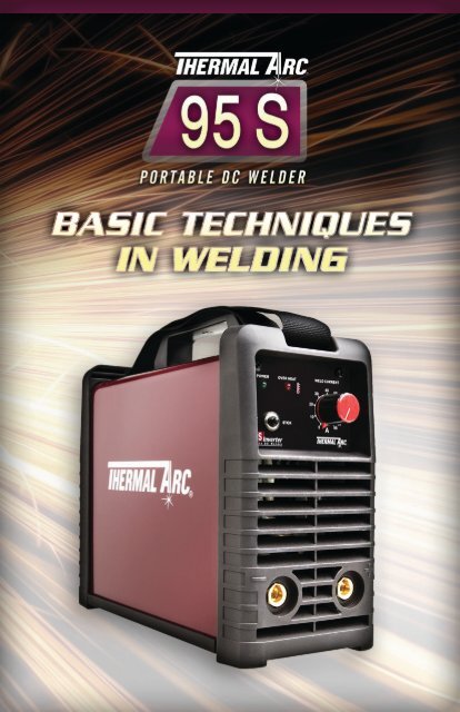
IntroducIng the thermal <strong>Arc</strong> <strong>95</strong>S<br />
So eASy <strong>to</strong> uSe. So hArd <strong>to</strong> be wIthout.<br />
<strong>Thermal</strong> <strong>Arc</strong> presents a one of a kind resourceful <strong>to</strong>ol for the do-it-<strong>your</strong>selfer. The <strong>95</strong>S is<br />
an easy-<strong>to</strong>-use welding unit that puts high quality Stick & Lift TIG welding capabilities<br />
in <strong>your</strong> hands.<br />
The <strong>95</strong>S is Perfect for:<br />
• Home Hobbyists • Small Businesses • Trade Schools<br />
• Maintenance and Repair • Light Fabrication<br />
Whether you’re a beginner or intermediate welder, the <strong>Thermal</strong> <strong>Arc</strong> <strong>95</strong> S provides you<br />
with everything you need <strong>to</strong> start mastering the art of welding.<br />
• Instructional DVD included • Ready <strong>to</strong> weld out of the box<br />
• Lightweight and Portable<br />
watch the <strong>95</strong>S in action at thermal<strong>Arc</strong><strong>95</strong>s.com<br />
For more information or <strong>to</strong> purchase <strong>your</strong> <strong>95</strong>S, contact<br />
thermadyne at 1-800-426-1888<br />
3
<strong>Thermal</strong> <strong>Arc</strong> Presents Basic Techniques in Welding<br />
<strong>Thermal</strong> <strong>Arc</strong> presents a helpful reference guide for beginning and intermediate<br />
welders. This guide was written <strong>to</strong> educate you on the basics of welding, including<br />
welding terminology, basic setup, safety precautions, Stick and TIG welding techniques,<br />
and types of welds and joints. This guide is not meant <strong>to</strong> replace training nor <strong>to</strong><br />
serve as a safety guide.<br />
I. Introduction <strong>to</strong> Welding<br />
<strong>Thermal</strong> <strong>Arc</strong> thanks you for <strong>your</strong> interest in this guide, and we’re thrilled you’ve chosen<br />
<strong>to</strong> further <strong>your</strong> interest in the world of welding. While welding may not be <strong>your</strong> area of<br />
expertise, we’d like <strong>to</strong> help you learn some basics. The information in this guide is an<br />
excellent reference <strong>to</strong> help you tackle several projects from those around <strong>your</strong> home and<br />
garage, <strong>to</strong> light fabrication, and maintenance / repair applications.<br />
4
Glossary of Terms<br />
Alloy<br />
A mixture with metallic properties composed of two or more elements, of which at least<br />
one is a metal.<br />
Amperage<br />
Amperage is a measure of how much electricity is flowing through <strong>your</strong> electrode, also<br />
referred <strong>to</strong> as current.<br />
<strong>Arc</strong><br />
The arc is the physical gap between the end of the electrode and the base of the metal while<br />
current is passing through.<br />
Bead<br />
A bead is the completed weld joint on the work surface produced when the electrode or wire<br />
is fused in<strong>to</strong> the base metal.<br />
Collet<br />
The piece inside the <strong>to</strong>rch body that holds the tungsten electrode in the TIG <strong>to</strong>rch.<br />
Consumable<br />
Consumable refers <strong>to</strong> an electrode, or component that is consumed or used during the welding<br />
process, such as an electrode coated in flux.<br />
Current<br />
Current is the flow of electricity through an electric circuit. Current is measured by amperage.<br />
Duty Cycle<br />
The Duty Cycle is the length of time a welding machine can operate during a ten-minute<br />
interval at a given amperage.<br />
Electrode<br />
Also called a welding rod, is a filler metal in the form of wire or rod, through which current<br />
is conducted between the electrode holder and the welding arc.<br />
5
Electrode Holder<br />
A device that holds the electrode (welding rod) and conducts electricity through the rod.<br />
Filler Metal<br />
Filler Metal is the material added <strong>to</strong> the weld pool typically <strong>to</strong> strengthen the weld joint.<br />
Flux<br />
A cleaning agent used <strong>to</strong> dissolve oxides, release trapped gases and slag, and <strong>to</strong> cleanse metals<br />
for welding, soldering, and brazing.<br />
Joint<br />
A joint is the intersection w<strong>here</strong> two pieces of metal meet. T<strong>here</strong> are many different types<br />
of welding joints.<br />
Lift <strong>Arc</strong><br />
Lift-<strong>Arc</strong> is a method of starting the arc during TIG welding. As the tungsten is lifted from<br />
the base metal, the arc is established.<br />
Polarity<br />
Electrical current has a negative and positive pole, thus giving it polarity. AC (Alternating<br />
Current) and DC (Direct Current) are types of electrical current.<br />
AC current reverses its direction in regular intervals, w<strong>here</strong>as DC current flows in one direction.<br />
Power Source<br />
The power source is the primary component of <strong>your</strong> welding system. It is <strong>your</strong> source of<br />
electrical power, and can provide adjustable current and/or voltage.<br />
Shielding Gas<br />
Protective gas used <strong>to</strong> prevent atmospheric contamination of the weld pool.<br />
Slag<br />
The hardened protective coating over the weld, produced when the flux on a welding rod<br />
melts while welding. Slag should be scraped / chipped from the weld and cleaned with<br />
a metal wire brush.<br />
Spatter<br />
Spatter is small droplets of filler metal that have blown out on<strong>to</strong> the work surface by the arc.<br />
6
Spot Weld<br />
A process in which two metal surfaces are joined by the heat from resistance <strong>to</strong> electric<br />
current flow, typically a very small weld size.<br />
Steel<br />
A type of metal that is made from mined iron ore, purified in blast furnaces, and then carbon<br />
is added during its molten stage.<br />
Stick Welding (SMAW, Shielded Metal <strong>Arc</strong> Welding)<br />
Stick welding uses a consumable electrode that is coated in flux <strong>to</strong> create the weld. An electric<br />
arc forms between the electrode and the base metal. As you weld, the flux coating melts from<br />
the electrode (which creates vapors that act as the shielding gas) and leaves behind a layer of<br />
slag that protects the weld from contamination.<br />
Stinger<br />
Stinger is another name for the electrode holder. You’ll typically hear it used in the shop<br />
or field.<br />
Tack Weld<br />
A tack weld refers <strong>to</strong> a small weld that is used <strong>to</strong> hold what you’re welding in its place.<br />
Tack welds can be broken if changes need <strong>to</strong> be made.<br />
Tensile Strength<br />
Tensile strength is an indication of a material’s ability <strong>to</strong> resist being pulled apart by tension.<br />
TIG Welding (GTAW, Gas Tungsten <strong>Arc</strong> Welding)<br />
TIG welding utilizes a non-consumable tungsten electrode, and in certain cases a separate<br />
filler metal. Current flows through the TIG Torch and electrode, while an inert gas passes<br />
through the <strong>to</strong>rch. The arc is created between the base metal and the tungsten electrode.<br />
The welding arc is shielded with an inert gas such as Argon.<br />
Weld Pool<br />
Also known as the weld puddle, the weld pool is the molten material produced while the arc<br />
is created, and during the welding process. It is important <strong>to</strong> protect the weld pool from<br />
contaminants while it solidifies.<br />
Wire Brush<br />
An important <strong>to</strong>ol for cleaning the welding surface both before and after welding.<br />
Voltage<br />
Voltage is the force that makes electrons flow through the conduc<strong>to</strong>r.<br />
7
Safety Precautions<br />
It’s always important <strong>to</strong> be familiar with the welding equipment you’re using. Be sure <strong>to</strong><br />
read the opera<strong>to</strong>r’s manual for safety precautions specific <strong>to</strong> <strong>your</strong> equipment.<br />
Electrical Shock<br />
T<strong>here</strong>’s always the threat of electrical shock when you’re welding, so taking proper<br />
measures <strong>to</strong> prevent this is a must every time you gear up <strong>to</strong> weld.<br />
• Never stand in water. Stand on a rubber mat or a dry area when welding.<br />
• Make sure <strong>your</strong> welding equipment doesn’t make contact with water.<br />
• Keep <strong>your</strong> clothes dry. This includes gloves, shoes, <strong>your</strong> shirt and pants, etc.<br />
Perspiration can make you more vulnerable <strong>to</strong> electrical shock.<br />
The Welding Environment<br />
The heat produced while welding is capable of igniting flammable materials.<br />
Be sure not <strong>to</strong> weld in areas containing flammable gases, vapors, or liquids.<br />
Proper Safety Attire<br />
As standard practice, you should always wear the proper clothing and safety equipment<br />
when welding. This includes, but is not limited <strong>to</strong>:<br />
• Eye protection • Welding helmet • Long sleeve shirts<br />
• Leather gloves • Pants that cover <strong>your</strong> legs • Close-<strong>to</strong>ed shoes<br />
8
II. Basic Setup<br />
Get <strong>to</strong> know <strong>your</strong> welding power source before you hook up anything. You should see<br />
a negative output terminal, a positive output terminal, and a knob that adjusts <strong>your</strong><br />
welding current.<br />
To set up for Stick Welding<br />
1. With the power source off and unplugged, connect the ground clamp cable <strong>to</strong> the<br />
negative output terminal, and the electrode holder cable <strong>to</strong> the positive output terminal.<br />
2. Connect the ground clamp <strong>to</strong> <strong>your</strong> work piece.<br />
3. Making sure the electrode holder is not <strong>to</strong>uching the work piece, plug the power<br />
cable in<strong>to</strong> the appropriate outlet, and turn the power source on.<br />
4. Make sure the process selection switch is set <strong>to</strong> STICK.<br />
5. Set the weld current control knob <strong>to</strong> the desired amperage.<br />
6. Install a stick electrode in the electrode holder.<br />
7. You are now ready <strong>to</strong> begin Stick welding.<br />
9
Stick (SMAW) Setup<br />
Set Process Selection<br />
Switch <strong>to</strong> Stick.<br />
Negative Output<br />
Terminal<br />
(Dinse 25)<br />
10<br />
200A<br />
Set Welding Current<br />
as specied by the<br />
Electrode Manufacturer.<br />
Positive Output<br />
Terminal<br />
(Dinse 25)<br />
Art #: A-08602
To set up for TIG Welding<br />
1. With the power source off and unplugged, connect the ground clamp <strong>to</strong> the positive<br />
output terminal, and the TIG <strong>to</strong>rch cable <strong>to</strong> the negative output terminal.<br />
2. Using a secured Argon cylinder, slowly crack open and then close the cylinder valve<br />
while standing off <strong>to</strong> the side. This will remove any debris that may be around the<br />
valve and regula<strong>to</strong>r seat area.<br />
3. Install the regula<strong>to</strong>r on the Argon cylinder and tighten with a wrench.<br />
4. Connect the gas hose <strong>to</strong> the outlet of the Argon regula<strong>to</strong>r, and tighten<br />
with a wrench.<br />
5. Be sure the gas valve on the <strong>to</strong>rch is closed, and slowly open the Argon Cylinder<br />
Valve <strong>to</strong> the fully open position and adjust the flow <strong>to</strong> approx 20 cfh.<br />
6. Connect the ground clamp <strong>to</strong> <strong>your</strong> work piece.<br />
7. Making sure the electrode holder is not <strong>to</strong>uching the work piece, plug the power<br />
cable in<strong>to</strong> the appropriate outlet, and turn the switch <strong>to</strong> the “ON” position.<br />
8. Make sure the process selection switch is set <strong>to</strong> LIFT TIG.<br />
9. Set the weld current control knob <strong>to</strong> the desired amperage.<br />
10. The tungsten must be ground <strong>to</strong> a blunt point in order <strong>to</strong> achieve optimum welding<br />
results. It is critical <strong>to</strong> grind the tungsten electrode in the direction the grinding<br />
wheel is turning.<br />
11. Install the tungsten with approximately 1/8” <strong>to</strong> ¼” sticking out from the gas cap,<br />
ensuring you have the correct sized collet.<br />
12. Tighten the back cap.<br />
13. You are now ready <strong>to</strong> begin TIG welding.<br />
11
Lift TIG (GTAW) Setup<br />
12
III. Starting with the Basics<br />
Basic Welding Techniques<br />
Relaxation is Important<br />
Place <strong>your</strong>self in a comfortable position before beginning <strong>to</strong> weld. Utilize a seat with<br />
the appropriate height and do as much work as possible sitting down. Don’t hold <strong>your</strong><br />
body tense. A taut attitude of mind and a tensed body will soon make you feel tired.<br />
Relax and you will find that the job becomes much easier. Proper safety equipment will<br />
keep you from being burned or sparks burning <strong>your</strong> clothes.<br />
Establishing an Electrical Circuit<br />
It’s important <strong>to</strong> establish an electrical circuit between the power source and the base<br />
metal. So make sure that the work clamp is making good electrical contact with the<br />
work piece, either directly or through the work table. For light gauge material, always<br />
clamp the work lead directly <strong>to</strong> the job, otherwise a poor circuit could result.<br />
Practice with Scrap<br />
The simplest way <strong>to</strong> practice welding is <strong>to</strong> run beads on a piece of scrap plate. Clean<br />
any paint, loose scale or grease off the plate and set it firmly on a solid surface like a<br />
work bench so that you can practice.<br />
The Line of Your Weld<br />
Position the scrap piece so you can pull the weld across <strong>your</strong> body, rather than <strong>to</strong> and<br />
from <strong>your</strong> body. The electrode holder lead should be clear of any obstruction so that<br />
you can move <strong>your</strong> arm <strong>free</strong>ly along as the electrode burns down. If the electrode cable<br />
is slung over <strong>your</strong> shoulder, it allows greater <strong>free</strong>dom of movement and takes a lot of<br />
weight off <strong>your</strong> hand. Be sure the insulation on <strong>your</strong> cable and electrode holder has no<br />
damage; otherwise you are risking electrical shock.<br />
STICK (SMAW) Electrode Polarity<br />
Stick electrode leads are generally connected <strong>to</strong> the “+” Positive Output Terminal and<br />
the work lead <strong>to</strong> the “−” Negative Output Terminal but if in doubt consult the electrode<br />
manufacturers literature for specific information.<br />
13
Types of STICK (SMAW) Electrodes<br />
<strong>Arc</strong> Welding electrodes are classified in<strong>to</strong> a number of groups depending on their<br />
applications. T<strong>here</strong> are a great number of electrodes used for specialized industrial<br />
purposes which are not of particular interest for everyday general work. These include<br />
some low hydrogen types for high tensile steel, cellulose types for welding large<br />
diameter pipes, etc. The range of electrodes dealt with in this publication will cover<br />
the vast majority of applications likely <strong>to</strong> be encountered.<br />
The ARC<br />
Striking the <strong>Arc</strong><br />
Before welding, practice striking the arc on a piece of scrap plate. To strike an arc,<br />
scratch the electrode along the plate’s surface in the same way a match is struck.<br />
As soon as the arc is established, maintain a 1/16” <strong>to</strong> 1/8” gap between the burning<br />
electrode and the base metal. Move the electrode slowly along <strong>your</strong> joint. A good weld<br />
will look like a line of coins layered along one another.<br />
Problems with Striking<br />
You may at first experience difficulty due <strong>to</strong> the electrode “sticking” <strong>to</strong> the work piece.<br />
This is caused by making contact with the work piece <strong>to</strong>o heavily and failing <strong>to</strong> withdraw<br />
the electrode quickly enough. Low amperage settings on <strong>your</strong> power source can<br />
accentuate this problem.<br />
14
Establishing the <strong>Arc</strong> Length<br />
Establishing a good arc length is necessary <strong>to</strong> produce a quality weld. After striking,<br />
maintain a 1/16” <strong>to</strong> 1/8” gap between the burning electrode and the work piece.<br />
A good arc will produce a crackling noise.<br />
Problems with <strong>Arc</strong> Length<br />
A common problem after the arc is established is the tendency <strong>to</strong> pull the electrode<br />
so far away from the weld piece that the arc breaks.<br />
A little practice and persistence and you’ll develop a feel for the correct length<br />
of <strong>your</strong> arc.<br />
Striking the <strong>Arc</strong><br />
Rate of Travel<br />
Direction of Travel<br />
After the arc is struck, <strong>your</strong> next concern is <strong>to</strong> maintain it, and this requires moving<br />
the electrode <strong>to</strong>wards the molten pool at the same rate as it is melting away. At the<br />
same time, the electrode has <strong>to</strong> move along the plate <strong>to</strong> form a bead. The electrode is<br />
directed at the weld pool at about 20 degrees from the vertical. The rate of travel has<br />
<strong>to</strong> be adjusted so that a well-formed bead is produced. If the travel is <strong>to</strong>o fast, the<br />
bead will be narrow and strung out and may even be broken up in<strong>to</strong> individual globules.<br />
If the travel is <strong>to</strong>o slow, the weld metal piles up and the bead will be <strong>to</strong>o large.<br />
15
IV. Types of Welds and Joints<br />
Making Welded Joints<br />
Convinced you can now weld like a pro? Well let’s not get ahead of ourselves. After<br />
practicing on scrap plates it’s time <strong>to</strong> move <strong>to</strong> welded joints. Having attained some<br />
skill in the handling of an electrode, you will be ready <strong>to</strong> create welded joints. Remember<br />
though, in many cases it will be possible <strong>to</strong> weld steel sections without any special<br />
preparation. However, for heavier sections and for repair work on castings, etc., it may<br />
be necessary <strong>to</strong> cut or grind an angle or a bevel, between the pieces being joined <strong>to</strong><br />
ensure proper penetration of the weld metal and <strong>to</strong> produce sound joints. In general,<br />
surfaces being welded should be clean and <strong>free</strong> of rust, scale, dirt, grease, etc. Slag<br />
should be removed from oxy-cut surfaces.<br />
Types of Welds & Joints<br />
A. Butt Weld Joints<br />
Set up two plates with their edges parallel, allowing 1/16” <strong>to</strong> 3/32” gap between them<br />
and tack weld at both ends. This is <strong>to</strong> prevent weld metal from pulling the plates out of<br />
alignment. Do not weave the electrode, but maintain a steady rate of travel along the<br />
joint sufficient <strong>to</strong> produce a well-formed bead. At first you may notice a tendency for<br />
undercut <strong>to</strong> form, but keeping the arc length short, the angle of the electrode needs <strong>to</strong><br />
be moved along fast enough <strong>to</strong> prevent the slag pool from getting ahead of the arc.<br />
Heavy plate may require several passes <strong>to</strong> complete the joint, and perhaps a small<br />
beveled edge. After completing the first pass, chip the slag out and clean the weld<br />
with a wire brush. It is important <strong>to</strong> do this <strong>to</strong> prevent slag being trapped by the<br />
second pass. Subsequent passes are then deposited using either a weave technique or<br />
single stringer beads. The width of weave should not be more than three times the core<br />
wire diameter of the electrode. When the joint is completely filled, the back can<br />
be machined, ground or gouged out <strong>to</strong> remove slag which may be trapped in the<br />
root, and <strong>to</strong> prepare a suitable joint for welding the back section.<br />
16
Typical Butt Weld Joint<br />
B. Fillet Weld Joints<br />
These typically are welds that join two sections meeting at right angles. Tack <strong>to</strong>gether a<br />
piece of angle iron, or two lengths of strip steel at right angles <strong>to</strong> begin. Strike the arc<br />
and immediately bring the electrode <strong>to</strong> a position perpendicular <strong>to</strong> the line of the fillet<br />
and about 45 degrees from vertical. Some electrodes require <strong>to</strong> be sloped about 20<br />
degrees away from the perpendicular position <strong>to</strong> prevent slag from running ahead of the<br />
weld. Do not attempt <strong>to</strong> build up <strong>to</strong>o much weld metal as it tends <strong>to</strong> sag, and undercut<br />
can form on the vertical leg.<br />
Typical Fillet Weld Joint<br />
17
C. Vertical Welds<br />
Tack weld a section of angle iron <strong>to</strong> <strong>your</strong> work bench in an upright position. Make<br />
<strong>your</strong>self comfortable on a seat and strike the arc in the corner of the fillet. The<br />
electrode needs <strong>to</strong> be about 10 degrees from the horizontal <strong>to</strong> enable a good bead <strong>to</strong><br />
be deposited. Use a short arc, and do not attempt <strong>to</strong> weave on the first pass. When<br />
the first pass has been completed chip the slag from the weld, wire bush it, and begin<br />
the second pass. This time a slight weaving motion may be necessary <strong>to</strong> cover the<br />
first pass and obtain good fusion at the edges. At the completion of each side motion,<br />
pause for a moment <strong>to</strong> allow weld metal <strong>to</strong> build up at the edges, otherwise undercut<br />
can form and <strong>to</strong>o much metal will accumulate in the center of the weld.<br />
Typical Vertical Fillet Weld<br />
18
Overhead Welds<br />
Apart from the rather awkward position, overhead welding is not that difficult. Set<br />
up a test piece for overhead welding by first tacking two pieces <strong>to</strong>gether forming right<br />
angles. Then tack this <strong>to</strong> the work bench or hold in a vice so that it is in the overhead<br />
position. The electrode is held at approximately 45 degrees <strong>to</strong> the horizontal and tilted<br />
10 degrees in the line of travel. The electrode may lightly <strong>to</strong>uch the metal, which helps<br />
it remain steady. A weave technique is not advisable for overhead fillet welds.<br />
Typical Overhead Weld Example<br />
19
Additional Weld Joint Types<br />
Open Square Butt<br />
Joint<br />
Gap varies from<br />
1/16” (1.6mm) <strong>to</strong> 3/16” (4.8mm)<br />
depending on plate thickness<br />
Single Vee Butt Joint<br />
Lap Joint<br />
Fillet Joint<br />
Corner Weld<br />
Plug Weld<br />
Not less than<br />
45°<br />
Single Vee Butt Joint<br />
Double Vee Butt Joint<br />
Tee Joints<br />
(Fillet both sides of the<br />
joint)<br />
20<br />
Edge Joint<br />
Plug Weld<br />
1.6mm (1/16”)<br />
1/16” (1.6mm)<br />
Not less than<br />
70°<br />
Not less than<br />
70°<br />
1/16” (1.6mm) max<br />
1/16” (1.6mm) max
Effects of Stick Welding Various Materials<br />
High Tensile and Alloy Steels<br />
The two most prominent effects of welding these steels are the formation of a hardened<br />
zone in the weld area, and, if suitable precautions are not taken, the occurrence in this<br />
zone of under-bead cracks. Hardened zone and under-bead cracks in the weld area may<br />
be reduced by using the correct electrodes, preheating, using higher current settings, or<br />
using larger electrodes sizes.<br />
Manganese Steels<br />
The effect on manganese steel of slow cooling from high temperatures is <strong>to</strong> embrittle it.<br />
For this reason it is absolutely essential <strong>to</strong> keep manganese steel cool during welding by<br />
quenching after each weld or skip welding <strong>to</strong> distribute the heat.<br />
Cast Iron<br />
Most types of cast iron, except white iron, are weldable. White iron, because of its<br />
extreme brittleness, generally cracks when attempts are made <strong>to</strong> weld it. Trouble may<br />
also be experienced when welding white-heart malleable, due <strong>to</strong> the porosity caused by<br />
gas held in this type of iron.<br />
Copper and Alloys<br />
The most important fac<strong>to</strong>r is the high rate of heat conductivity of copper, making<br />
pre-heating of heavy sections necessary <strong>to</strong> give proper fusion of weld and base metal.<br />
TIG (Gas Tungsten <strong>Arc</strong> Welding, GTAW)<br />
TIG (GTAW) Electrode Polarity<br />
Connect the TIG <strong>to</strong>rch <strong>to</strong> the “-” Negative Output Terminal and the work lead <strong>to</strong> the<br />
“+” Positive Output Terminal for direct current straight polarity. Direct current straight<br />
polarity is the most widely used polarity for DC TIG welding. It allows limited wear of the<br />
electrode since 70% of the heat is concentrated at the work piece.<br />
21
Tungsten Preparation & Sharpening<br />
For DC TIG welding, it is ideal <strong>to</strong> sharpen the tungsten electrode <strong>to</strong> a blunt point. This<br />
will help concentrate the welding arc as you complete the joint. Be sure <strong>to</strong> hold the<br />
tungsten in line with the direction the grinding wheel is turning. This will ensure the<br />
“grind marks” are running in line with the tungsten <strong>to</strong> help direct the current <strong>to</strong> the<br />
work piece.<br />
Basic Tungsten Electrode Types<br />
TIG Welding Direction of Travel and Torch Position<br />
Direction of travel should progress away from the section being welded. Torch angle<br />
should be that so the filler rod and <strong>to</strong>rch form approximately a 90 degree angle.<br />
The <strong>to</strong>rch should also be angled slightly <strong>to</strong>wards the direction you are traveling.<br />
22
TIG Welding Parameters<br />
Tungsten Electrode Current Ranges<br />
Shielding Gas Selection<br />
Typical shielding gas flow rates can range between 10-25 cubic feet per hour (cfh).<br />
Filler Rods<br />
Filler rods ranging in various sizes may be used <strong>to</strong> “dip” in<strong>to</strong> the weld pool <strong>to</strong> strengthen<br />
the weld joint. Most come in 36” cut lengths, and different alloys. Be sure <strong>to</strong> choose<br />
the appropriate alloy for <strong>your</strong> application.<br />
23


