For Details
For Details
For Details

Create successful ePaper yourself
Turn your PDF publications into a flip-book with our unique Google optimized e-Paper software.
PRL 99, 066805 (2007)<br />
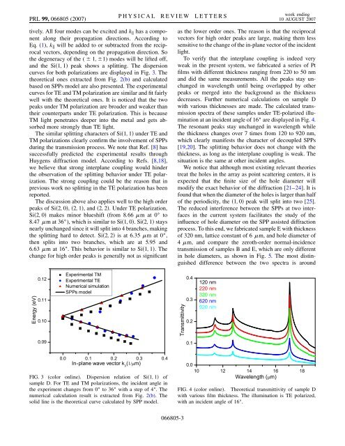
tively. All four modes can be excited and k k has a component<br />
along their propagation directions. According to<br />
Eq. (1), k k will be added to or subtracted from the reciprocal<br />
vectors, depending on the propagation direction. So<br />
the degeneracy of the ( 1; 1) modes will be lifted off,<br />
and the Si 1; 1 peak shows a splitting. The dispersion<br />
curves for both polarizations are displayed in Fig. 3. The<br />
theoretical ones extracted from Fig. 2(b) and calculated<br />
based on SPPs model are also presented. The experimental<br />
curves for TE and TM polarization are similar and fit fairly<br />
well with the theoretical ones. It is noticed that the two<br />
peaks under TM polarization are broader and weaker than<br />
their counterparts under TE polarization. This is because<br />
TM light penetrates deeper into the metal and gets absorbed<br />
more strongly than TE light.<br />
The similar splitting characters of Si 1; 1 under TE and<br />
TM polarizations clearly confirm the involvement of SPPs<br />
during the transmission process. We note that Ref. [8] has<br />
successfully predicted the experimental results through<br />
Huygens diffraction model. According to Refs. [8,18],<br />
we believe that strong interplane coupling would hinder<br />
the observation of the splitting behavior under TE polarization.<br />
The strong coupling could be the reason that in<br />
previous work no splitting in the TE polarization has been<br />
reported.<br />
The discussion above also applies well to the high order<br />
peaks of Si 2; 0 , 2; 1 , and 2; 2 . Under TE polarization,<br />
Si 2; 0 makes minor blueshift (from 8:66 m at 0 to<br />
8:47 m at 36 ), which is similar to Si 1; 0 . Si 2; 1 stays<br />
nearly unchanged since it will split into 4 branches, making<br />
the splitting hard to detect. Si 2; 2 is at 6:35 m at 0 ,<br />
then splits into two branches, which are at 5.95 and<br />
6:63 m at 16 . This behavior is similar to Si 1; 1 . The<br />
change for high order peaks is generally not as significant<br />
-<br />
FIG. 3 (color online). Dispersion relation of Si 1; 1 of<br />
sample D. <strong>For</strong> TE and TM polarizations, the incident angle in<br />
the experiment changes from 0 to 36 with a step of 4 . The<br />
numerical calculation result is extracted from Fig. 2(b). The<br />
solid line is the theoretical curve calculated by SPP model.<br />
PHYSICAL REVIEW LETTERS week ending<br />
10 AUGUST 2007<br />
066805-3<br />
as the lower order ones. The reason is that the reciprocal<br />
vectors for high order peaks are large, making them less<br />
sensitive to the change of the in-plane vector of the incident<br />
light.<br />
To verify that the interplane coupling is indeed very<br />
weak in the present system, we fabricated a series of Pt<br />
films with different thickness ranging from 220 to 50 nm<br />
and did the same measurements. All the peaks stay unchanged<br />
in wavelength until being overlapped by other<br />
peaks or merged into the background as the thickness<br />
decreases. Further numerical calculations on sample D<br />
with various thicknesses are made. The calculated transmission<br />
spectra of these samples under TE-polarized illumination<br />
at an incident angle of 16 are displayed in Fig. 4.<br />
The resonant peaks stay unchanged in wavelength while<br />
the thickness changes over 7 times from 120 to 920 nm,<br />
which clearly manifests the character of decoupled SPPs<br />
[19,20]. The splitting behavior does not change with the<br />
thickness, as long as the interplane coupling is weak. The<br />
situation is the same at other incident angles.<br />
We notice that although most existing relevant theories<br />
treat the holes in the array as point scattering centers, it is<br />
expected that the finite size of the hole diameter will<br />
modify the exact behavior of the diffraction [21–24]. It is<br />
found that when the diameter of the holes is larger than half<br />
of the periodicity, the 1; 0 peak will split into two [25].<br />
The reduced interference between the SPPs at two interfaces<br />
in the current system facilitates the study of the<br />
influence of hole diameter on the SPP assisted diffraction<br />
process. To this end, we fabricated sample E with thickness<br />
of 320 nm, lattice constant of 6 m, and hole diameter of<br />
4 m, and compare the zeroth-order normal-incidence<br />
transmission of samples B and E, which are only different<br />
in hole diameters, as shown in Fig. 5. The most distinguished<br />
difference between the two spectra is around<br />
FIG. 4 (color online). Theoretical transmittivity of sample D<br />
with various film thickness. The illumination is TE polarized,<br />
with an incident angle of 16 .