

MT-031: Grounding Data Converters and Solving ... - Analog Devices
MT-031: Grounding Data Converters and Solving ... - Analog Devices
MT-031: Grounding Data Converters and Solving ... - Analog Devices

You also want an ePaper? Increase the reach of your titles
YUMPU automatically turns print PDFs into web optimized ePapers that Google loves.
<strong>MT</strong>-<strong>031</strong><br />
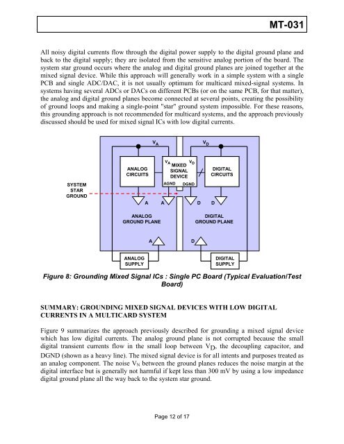
All noisy digital currents flow through the digital power supply to the digital ground plane <strong>and</strong><br />
back to the digital supply; they are isolated from the sensitive analog portion of the board. The<br />
system star ground occurs where the analog <strong>and</strong> digital ground planes are joined together at the<br />
mixed signal device. While this approach will generally work in a simple system with a single<br />
PCB <strong>and</strong> single ADC/DAC, it is not usually optimum for multicard mixed-signal systems. In<br />
systems having several ADCs or DACs on different PCBs (or on the same PCB, for that matter),<br />
the analog <strong>and</strong> digital ground planes become connected at several points, creating the possibility<br />
of ground loops <strong>and</strong> making a single-point "star" ground system impossible. For these reasons,<br />
this grounding approach is not recommended for multicard systems, <strong>and</strong> the approach previously<br />
discussed should be used for mixed signal ICs with low digital currents.<br />
SYSTEM<br />
STAR<br />
GROUND<br />
ANALOG<br />
CIRCUITS<br />
V A<br />
ANALOG<br />
GROUND PLANE<br />
ANALOG<br />
SUPPLY<br />
VA VD MIXED<br />
SIGNAL<br />
DEVICE<br />
AGND DGND<br />
A A D D<br />
A<br />
D<br />
V D<br />
DIGITAL<br />
CIRCUITS<br />
DIGITAL<br />
GROUND PLANE<br />
DIGITAL<br />
SUPPLY<br />
Figure 8: <strong>Grounding</strong> Mixed Signal ICs : Single PC Board (Typical Evaluation/Test<br />
Board)<br />
SUMMARY: GROUNDING MIXED SIGNAL DEVICES WITH LOW DIGITAL<br />
CURRENTS IN A MULTICARD SYSTEM<br />
Figure 9 summarizes the approach previously described for grounding a mixed signal device<br />
which has low digital currents. The analog ground plane is not corrupted because the small<br />
digital transient currents flow in the small loop between V D , the decoupling capacitor, <strong>and</strong><br />
DGND (shown as a heavy line). The mixed signal device is for all intents <strong>and</strong> purposes treated as<br />
an analog component. The noise VN between the ground planes reduces the noise margin at the<br />
digital interface but is generally not harmful if kept less than 300 mV by using a low impedance<br />
digital ground plane all the way back to the system star ground.<br />
Page 12 of 17


