

MT-031: Grounding Data Converters and Solving ... - Analog Devices
MT-031: Grounding Data Converters and Solving ... - Analog Devices
MT-031: Grounding Data Converters and Solving ... - Analog Devices

Create successful ePaper yourself
Turn your PDF publications into a flip-book with our unique Google optimized e-Paper software.
<strong>MT</strong>-<strong>031</strong><br />
together externally to the analog ground plane with minimum lead lengths. Any extra impedance<br />
in the DGND connection will cause more digital noise to be developed at point B; it will, in turn,<br />
couple more digital noise into the analog circuit through the stray capacitance. Note that<br />
connecting DGND to the digital ground plane applies V NOISE across the AGND <strong>and</strong> DGND<br />
pins <strong>and</strong> invites disaster!<br />
The name "DGND" on an IC tells us that this pin connects to the digital ground of the IC. This<br />
does not imply that this pin must be connected to the digital ground of the system.<br />
It is true that this arrangement may inject a small amount of digital noise onto the analog ground<br />
plane. These currents should be quite small, <strong>and</strong> can be minimized by ensuring that the converter<br />
output does not drive a large fanout (they normally can't, by design). Minimizing the fanout on<br />
the converter's digital port will also keep the converter logic transitions relatively free from<br />
ringing <strong>and</strong> minimize digital switching currents, <strong>and</strong> thereby reducing any potential coupling into<br />
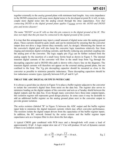
the analog port of the converter. The logic supply pin (VD ) can be further isolated from the<br />
analog supply by the insertion of a small lossy ferrite bead as shown in Figure 5. The internal<br />
transient digital currents of the converter will flow in the small loop from VD through the<br />
decoupling capacitor <strong>and</strong> to DGND (this path is shown with a heavy line on the diagram). The<br />
transient digital currents will therefore not appear on the external analog ground plane, but are<br />
confined to the loop. The VD pin decoupling capacitor should be mounted as close to the<br />
converter as possible to minimize parasitic inductance. These decoupling capacitors should be<br />
low inductance ceramic types, typically between 0.01 µF <strong>and</strong> 0.1 µF.<br />
TREAT THE ADC DIGITAL OUTPUTS WITH CARE<br />
It is always a good idea (as shown in Figure 5) to place a buffer register adjacent to the converter<br />
to isolate the converter's digital lines from noise on the data bus. The register also serves to<br />
minimize loading on the digital outputs of the converter <strong>and</strong> acts as a Faraday shield between the<br />
digital outputs <strong>and</strong> the data bus. Even though many converters have three-state outputs/inputs,<br />
this isolation register still represents good design practice. In some cases it may be desirable to<br />
add an additional buffer register on the analog ground plane next to the converter output to<br />
provide greater isolation.<br />
The series resistors (labeled "R" in Figure 5) between the ADC output <strong>and</strong> the buffer register<br />
input help to minimize the digital transient currents which may affect converter performance.<br />
The resistors isolate the digital output drivers from the capacitance of the buffer register inputs.<br />
In addition, the RC network formed by the series resistor <strong>and</strong> the buffer register input<br />
capacitance acts as a lowpass filter to slow down the fast edges.<br />
A typical CMOS gate combined with PCB trace <strong>and</strong> a through-hole will create a load of<br />
approximately 10 pF. A logic output slew rate of 1 V/ns will produce 10 mA of dynamic current<br />
if there is no isolation resistor:<br />
Δv<br />
1 V<br />
Δ I = C = 10 pF × = 10 mA . Eq. 2<br />
Δt<br />
ns<br />
Page 8 of 17


