

MT-031: Grounding Data Converters and Solving ... - Analog Devices
MT-031: Grounding Data Converters and Solving ... - Analog Devices
MT-031: Grounding Data Converters and Solving ... - Analog Devices

You also want an ePaper? Increase the reach of your titles
YUMPU automatically turns print PDFs into web optimized ePapers that Google loves.
<strong>MT</strong>-<strong>031</strong><br />
The second approach ("star ground") is often used in high speed mixed-signal systems having<br />
separate analog <strong>and</strong> digital ground systems <strong>and</strong> warrants further discussion.<br />
SEPARATING ANALOG AND DIGITAL GROUND PLANES<br />
In mixed-signal systems with large amounts of digital circuitry, it is highly desirable to<br />
physically separate sensitive analog components from noisy digital components. It may also be<br />
beneficial to use separate ground planes for the analog <strong>and</strong> the digital circuitry. These planes<br />
should not overlap in order to minimize capacitive coupling between the two. The separate<br />
analog <strong>and</strong> digital ground planes are continued on the backplane using either motherboard<br />
ground planes or "ground screens" which are made up of a series of wired interconnections<br />
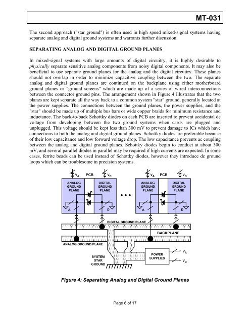
between the connector ground pins. The arrangement shown in Figure 4 illustrates that the two<br />
planes are kept separate all the way back to a common system "star" ground, generally located at<br />
the power supplies. The connections between the ground planes, the power supplies, <strong>and</strong> the<br />
"star" should be made up of multiple bus bars or wide copper braids for minimum resistance <strong>and</strong><br />
inductance. The back-to-back Schottky diodes on each PCB are inserted to prevent accidental dc<br />
voltage from developing between the two ground systems when cards are plugged <strong>and</strong><br />
unplugged. This voltage should be kept less than 300 mV to prevent damage to ICs which have<br />
connections to both the analog <strong>and</strong> digital ground planes. Schottky diodes are preferable because<br />
of their low capacitance <strong>and</strong> low forward voltage drop. The low capacitance prevents ac coupling<br />
between the analog <strong>and</strong> digital ground planes. Schottky diodes begin to conduct at about 300<br />
mV, <strong>and</strong> several parallel diodes in parallel may be required if high currents are expected. In some<br />
cases, ferrite beads can be used instead of Schottky diodes, however they introduce dc ground<br />
loops which can be troublesome in precision systems.<br />
V A<br />
ANALOG<br />
GROUND<br />
PLANE<br />
DIGITAL<br />
GROUND<br />
PLANE<br />
A D<br />
ANALOG GROUND PLANE<br />
PCB PCB<br />
SYSTEM<br />
STAR<br />
GROUND<br />
V D<br />
DIGITAL GROUND PLANE<br />
V A<br />
ANALOG<br />
GROUND<br />
PLANE<br />
POWER<br />
SUPPLIES<br />
DIGITAL<br />
GROUND<br />
PLANE<br />
A D<br />
BACKPLANE<br />
Figure 4: Separating <strong>Analog</strong> <strong>and</strong> Digital Ground Planes<br />
Page 6 of 17<br />
V D<br />
V A<br />
V D


