Laboratory Evaluation of the OASys Indirect/Direct Evaporative
Laboratory Evaluation of the OASys Indirect/Direct Evaporative
Laboratory Evaluation of the OASys Indirect/Direct Evaporative

You also want an ePaper? Increase the reach of your titles
YUMPU automatically turns print PDFs into web optimized ePapers that Google loves.
System Description<br />
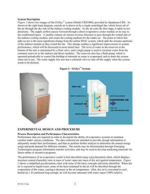
Figure 1 shows two images <strong>of</strong> <strong>the</strong> <strong>OASys</strong> system (Model CRS1000), provided by Speakman CRS. As<br />
shown in <strong>the</strong> right-hand diagram, outside air is drawn in by a single centrifugal fan, which forces all <strong>of</strong><br />
<strong>the</strong> air through <strong>the</strong> dry side <strong>of</strong> <strong>the</strong> indirect cooling module. As <strong>the</strong> air exits <strong>the</strong> first stage, it splits in two<br />
directions. The supply airflow passes forward through a direct evaporative cooler module on its way to<br />
<strong>the</strong> conditioned space. A smaller exhaust air stream reverses direction to pass through <strong>the</strong> wetted side <strong>of</strong><br />
<strong>the</strong> indirect cooling module, and create <strong>the</strong> cooling medium for <strong>the</strong> intake air. The point at which this<br />
split occurs is <strong>the</strong> most significant change from <strong>the</strong> earlier IDAC system, which split <strong>the</strong> streams upstream<br />
<strong>of</strong> <strong>the</strong> indirect module as <strong>the</strong>y exited <strong>the</strong> fan. This change enables a significant improvement in system<br />
performance, which will be discussed in more detail later. The level <strong>of</strong> water in <strong>the</strong> reservoir at <strong>the</strong><br />
bottom <strong>of</strong> <strong>the</strong> unit is maintained by a float valve, and a single pump is used to circulate water from <strong>the</strong><br />
common reservoir to <strong>the</strong> indirect and direct modules. The reservoir also has a flush pump, which is<br />
operated periodically to control <strong>the</strong> buildup <strong>of</strong> minerals as water is evaporated, and to drain <strong>the</strong> system<br />
when not in use. The water supply line also has a solenoid valve to shut <strong>of</strong>f <strong>the</strong> supply when <strong>the</strong> system<br />
needs to be drained.<br />
Figure 1: <strong>OASys</strong> System<br />
EXPERIMENTAL DESIGN AND PROCEDURE<br />
Process Description and Performance Characteristics<br />
Performance data are required in order to document <strong>the</strong> ability <strong>of</strong> evaporative systems to maintain<br />
comfort under various conditions. The data collected are intended to provide enough information to<br />
adequately model <strong>the</strong>ir performance, and thus to perform fur<strong>the</strong>r analysis to determine <strong>the</strong> annual energy<br />
usage and peak demand for different climates. The results may be disseminated through Emerging<br />
Technologies program information transfer activities, and may be used to develop marketing materials for<br />
future rebate or incentive programs.<br />
The performance <strong>of</strong> an evaporative cooler is best described using a psychrometric chart, which displays<br />
moisture content (humidity ratio in mass <strong>of</strong> water vapor per mass <strong>of</strong> dry air) against temperature. Figure<br />
2 shows a simplified psychrometric chart with some <strong>of</strong> <strong>the</strong> basic concepts and terms identified. When dry<br />
air is exposed to liquid water, some <strong>of</strong> <strong>the</strong> heat contained in <strong>the</strong> air will be absorbed through <strong>the</strong><br />
evaporation <strong>of</strong> <strong>the</strong> water, causing a decrease in <strong>the</strong> air temperature. (Hot, dry air is converted to cool,<br />
humid air.) If continued long enough, air will become saturated with water vapor (100% relative<br />
491-06.12.doc 2