- RMA 5 pol - Mikroskop Technik Rathenow Gmbh
- RMA 5 pol - Mikroskop Technik Rathenow Gmbh
- RMA 5 pol - Mikroskop Technik Rathenow Gmbh

Create successful ePaper yourself
Turn your PDF publications into a flip-book with our unique Google optimized e-Paper software.
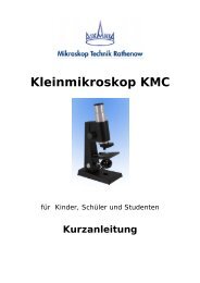
Polarization Microscope - <strong>RMA</strong> 5 <strong>pol</strong><br />
Technical Incident Light Microscope - <strong>RMA</strong> 5<br />
User Guide
Table of contents<br />
1. Safety Instructions<br />
1.1. Characteristics and Applications…………………………………………….. 5<br />
1.2. Assembly and Operation <strong>RMA</strong> 5 <strong>pol</strong>….……………………………………. 6<br />
1.3. Technical Data <strong>RMA</strong> 5 <strong>pol</strong>…………………………………………………. 7<br />
1.4. Assembly and Operation <strong>RMA</strong> 5……………………………………………. 8<br />
1.5. Technical Data <strong>RMA</strong> 5………………………………………………………. 9<br />
2. Starting Operations<br />
2.1 Assembly……………………………………………………………………… 10<br />
2.2 Adjusting the sharpness………………………………………………………. 10<br />
2.3. Incident light illumination………………………………………………………11<br />
2.4 Polarization units……………………………………………………………… 11<br />
2.4.1 Incident light <strong>pol</strong>arization………………………………………… 11<br />
2.4.2 Transmitted light <strong>pol</strong>arization…………………………………….. 12<br />
2.4.3 Compensator……………………………………………………… 12<br />
2.5. General Operating Instructions………………………………………………. 13<br />
2.5.1. Vertical adjustment of the Microscope…………………………… 13<br />
2.5.2 Optimising the illumination……………………………………….. 13<br />
2.5.3 Changing the tubes………………………………………………. 13<br />
2.5.4. Changing the objectives…………………………………………. 13<br />
2.5.5. Changing the eyepieces…………………………………………. 13<br />
3. Maintenance and Service<br />
3.1. Changing the fuse……………………………………………………………. 14<br />
3.1.1. <strong>RMA</strong> 5…………………………………………………………….. 14<br />
3.2. Care of components………………………………………………………… 14<br />
3.2.1. Dioptre rings………………………………………………………. 14<br />
3.2.2. Eyepieces, Tubes and Objectives……………………………….. 14<br />
3.2.3. Microscope……………………………………………………….. 14<br />
3.2.4. Gliding stage…………………………………………………….. 14<br />
4. Supplementary Equipment<br />
4.1. Eyepieces…………………………………………………………………….. 15<br />
4.1.1. Fixed eyepieces………………………………………………….. 15<br />
4.1.2. Adjustable eyepieces …………………………………………….. 15<br />
4.2. Tubes………………………………………………………………………….. 15<br />
4.2.1. Monocular straight tube …………………………………………. 15<br />
4.2.2. Binocular straight tube……………………………………………. 15<br />
4.3. Objectives ……………………………………………………………………. 16<br />
4.4. Color filter…………………………………………………………………….. 16<br />
3
5. Intermediate Tubes<br />
5.1. Angled tube…………………………………………………………………... 16<br />
5.2. Photo-/TV tube……………………………………………………………….. 16<br />
5.3. Wide field Photo Tube for M-Plan objectives……………………………….. 17<br />
6. Measuring instruments<br />
6.1. Eyepiece with measuring plate………………………………………………. 17<br />
6.2. Object measuring plate………………………………………………………. 17<br />
6.3. Measuring software………………………………………………………….. 17<br />
7. Documentation<br />
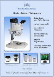
7.1. Photography over Photo-/TV tube…………………………………………… 18<br />
7.2. Digital photography………………………………………………………….. 18<br />
8. TV – Transfer<br />
8.1. TV-Transfer over Photo-/TV tube…………………………………………….. 19<br />
8.1.1. TV – Adapter 1,0x……………………………………………….. 19<br />
8.1.2 TV - Adapter 0,3x; 0,4x; 0,4xWF; 0,63x; 1,6x….…………. 19<br />
9. Illumination<br />
9.1. 3W-LED transmitted light…………………………………………………….. 20<br />
9.2. Oblique incident light (dark field)……………………………………………. 20<br />
10. Stages<br />
10.1. Gliding stage…………………………………………………………………. 21<br />
10.2. Stage carrier with object guide……………………………………………… 21<br />
10.3. Stage carrier with rotary stage………………………………………………. 21<br />
10.4. Magnet spherical stage……………………………………………………… 21<br />
10.5 Depth measurement………………………………………………………….. 22<br />
10.5.1 with combination drive…………………………………………… 22<br />
10.5.2 with coaxial coarse and fine drive………………………………. 22<br />
10.5.3 with dial indicator gauge………………………………………… 22<br />
11. System overview……………………………………………………………… 23<br />
12. Complaints, Warranty……………………………………………………….. 24<br />
4
1. Safety Instructions<br />
CAUTION! Please read the following<br />
information carefully before using the unit and its<br />
supplementary equipment!<br />
This unit was constructed and checked<br />
according to the safety regulations for electronic<br />
measuring devices, and was delivered securely.<br />
This User Manual contains information and<br />
warning notices that should be heeded by the<br />
user.<br />
The unit is a light microscope, drafted according<br />
to the newest scientific and technical knowledge<br />
for the visual, micro photographic and videotechnical<br />
investigation of microscopic objects.<br />
The unit should only be used for the designed<br />
purpose. All other uses (also the insertion of<br />
single components which were not designed by<br />
the manufacturer) constitute a misuse of the<br />
product. We are not liable for any damages<br />
caused by this misuse.<br />
This unit is not meant for unattended continuous<br />
operation.<br />
The microscope does not have any special<br />
safeguards against samples with caustic toxic,<br />
radioactive or other hazardous materials. The<br />
allowed sample amount may not be exceeded.<br />
The unit may only be operated on the voltages<br />
indicated on the unit. Please heed the<br />
instructions in the user manual! We are not liable<br />
for any damages caused by the disregard of<br />
these instructions.<br />
If the unit is connected to voltage, contact<br />
clamps can lead to dangerous voltages and<br />
opening the coverings or removing parts can<br />
uncover a piece under a dangerous voltage.<br />
The unit must be disconnected from power<br />
before it can be opened for adjustments,<br />
replacements, servicing or repairs.<br />
5<br />
Existing ventilation slits should not be obstructed.<br />
This also applies for ventilation slits on the<br />
bottom of the unit. No tools, loose objects or<br />
liquids should enter the unit through ventilation<br />
slits or other openings in the unit.<br />
Only fuses with the required nominal current may<br />
be used as substitutes for the prescribed use. It is<br />
prohibited to use makeshift fuses or short-circuit<br />
the fuse support.<br />
If safety is endangered , the unit must be<br />
removed from use and secured against<br />
unattended operation. The unit should then be<br />
sent to the production factory or a competent<br />
service technician.<br />
Before switching on the unit, set the controller for<br />
the illumination intensity to the left catch in order<br />
to prevent blinding.<br />
1.1. Characteristics and Application<br />
The microscope <strong>RMA</strong> 5 is equipped with high<br />
quality optics, and excels due to its high optical<br />
performance.<br />
The following additional devices are available:<br />
evaluation of investigations over Photo-/TV<br />
adapter and digital cameras, Polarization<br />
equipment, measuring software...<br />
Different interchangeable objectives and<br />
eyepieces, which can be changed easily by a<br />
revolver (quadruple), make an extension area in<br />
an interval of 50x ... 640x possible (standard<br />
configuration).
1.2. Assembly and Operation <strong>RMA</strong> 5 <strong>pol</strong><br />
The <strong>pol</strong>arization microscope <strong>RMA</strong> 5 <strong>pol</strong> comes<br />
with a fixed stand. All further components of the<br />
microscope are mounted on this stand. There is<br />
a <strong>pol</strong>.-suited binocular straight tube with wide<br />
field eyepieces (spectacles) for a research of<br />
objects.<br />
The microscope <strong>RMA</strong> 5 <strong>pol</strong> is assembled with a<br />
revolving nosepiece (quadruple) and four M-Plan<br />
∞ objectives.. The ball bearing revolver has click<br />
stops for the positions of each objective.<br />
There are three stages for fixing the objects<br />
under the microscope (gliding stage, stage<br />
carrier with object guide and stage carrier with<br />
rotary stage). The objects will be illuminated by<br />
a 3W-LED incident light or transmitted light<br />
illumination (Koehler principle).<br />
All electronic parts for the illumination are<br />
integrated into the microscope base. There is a<br />
control for adjusting the illumination in front and<br />
on the side of the microscope base. It is also<br />
possible to add other kind of illuminations to the<br />
microscope (transmitted light illumination, striped<br />
incident light).<br />
Further information, how <strong>pol</strong>arization microscopy<br />
is working, you can find in special literature.<br />
We will describe only necessary features of the<br />
microscope <strong>RMA</strong> 5 <strong>pol</strong> at the following pages.<br />
6<br />
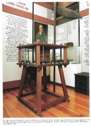
Polarization Microscope <strong>RMA</strong> 5 <strong>pol</strong><br />
pic.1: overview <strong>RMA</strong> 5 <strong>pol</strong><br />
1 Eyecup with eyepiece<br />
2 Binocular straight tube<br />
3 Angled tube / photo /TV tube 1x/0,8x<br />
4 Incident light <strong>pol</strong>arization tube<br />
5 Revolving nosepiece with objectives<br />
6 Microscope stage<br />
7 Stage holder<br />
8 Microscope base<br />
9 Microscope stand<br />
10 Coaxial coarse and fine drive adjustment
1.3. Technical Data <strong>RMA</strong> 5 <strong>pol</strong><br />
With Semi- Apochromat ∞ Objectives (standard)<br />
Objective (incident light) M-Plan ∞<br />
5x; 10x; 20x; 50x<br />
Eyepiece GF-Pw 10x/ 20<br />
Tube factor 1x Visuell<br />
0,8x photo/TV<br />
Illumination<br />
Koehler principle with filter holder,<br />
field diaphragm and aperture diaphragm<br />
Total magnification<br />
V t = V obj x V eyep 50x ... 500x<br />
Object field (mm) 4,0... 0,4<br />
Adjustable range of coarse drive 20 mm<br />
Max. High of objects 35 mm<br />
Interpupillary adjustment 55...80 mm<br />
Adjustment ametropia +/- 6 dpt<br />
Adjustment Object-guide 40 mm x 20 mm<br />
Adjustment Gliding stage d = 40 mm<br />
Coaxial coarse and fine drive<br />
Resolution 2 µm<br />
7
1.4. Assembly and Operation <strong>RMA</strong> 5<br />
The incident light microscope <strong>RMA</strong> 5 comes with<br />
a fixed stand. All further components of the<br />
microscope are mount on this stand. There is a<br />
binocular straight tube with wide field eyepieces<br />
(spectacles) for a research of objects.<br />
The microscope <strong>RMA</strong> 5 is assembled with a<br />
revolving nosepiece (quadruple) and four M-Plan<br />
∞ objectives. Alternative you can use achromatic<br />
corrected objectives and semi plan achromatic<br />
objectives for a mechanical tube length of<br />
160mm. The ball bearing revolver has click<br />
stops for the positions of each objective.<br />
There are four stages for fixing the objects under<br />
the microscope (gliding stage, magnet spherical<br />
stage, stage carrier with object guide and stage<br />
carrier with rotary stage). The objects will be<br />
illuminated by a 3W-LED incident light<br />
illumination (Koehler principle).<br />
All electronic parts for the illumination are<br />
integrated into the microscope base. There is a<br />
control for adjusting the illumination in front of<br />
the microscope base. It is also possible to add<br />
other kind of illuminations to the microscope<br />
(transmitted light illumination, striped incident<br />
light).<br />
Further information, how a incident light<br />
microscope is working, you can find in special<br />
literature.<br />
We will describe only necessary features of the<br />
microscope <strong>RMA</strong> 5 at the following pages.<br />
8<br />
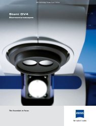
Technical – Incident Light Microscope <strong>RMA</strong> 5<br />
pic.2: overview <strong>RMA</strong> 5<br />
1 Eyecup with eyepiece<br />
2 Binocular straight tube<br />
3 Angled tube<br />
4 Incident light tube<br />
5 Revolving nosepiece with objectives<br />
6 Microscope stage<br />
7 Stage holder<br />
8 Microscope base<br />
9 Microscope stand<br />
10 Combined Coaxial coarse and fine<br />
drive adjustment
1.5. Technical Data <strong>RMA</strong> 5<br />
Microscope: E-Plan ∞ Objectives<br />
Objectives (incident light) M-Plan ∞<br />
5x; 10x; 20x; 50x<br />
Eyepiece GF-Pw 10x/ 20<br />
Tube Factor 1x<br />
Illumination<br />
Koehler principle with filter holder,<br />
field diaphragm and aperture diaphragm<br />
Total magnification<br />
V t = V obj x V eyep 50x ... 500x<br />
Object field (mm) 4,0... 0,4<br />
Adjustable range of coarse drive 15 mm<br />
Max. High of objects 35 mm<br />
Interpupillary adjustment 55...80 mm<br />
Adjustment ametropia +/- 6 dpt<br />
Adjustment Object-guide 76 mm x 26 mm<br />
Adjustment Gliding stage d = 40 mm<br />
Coaxial coarse and fine drive<br />
Resolution 2 µm<br />
9<br />
Microscope: Achromatic 160mm Objectives<br />
Objectives<br />
4x; 10x; 20x; 40x<br />
Eyepiece GF 10x/ 18<br />
Tube Factor 1,6x<br />
Illumination<br />
Koehler principle with filter holder,<br />
field diaphragm and aperture diaphragm<br />
Total magnification<br />
V t = V obj x V eyep 64x... 640x<br />
Object field (mm) 2,8... 0,28<br />
Adjustable range of coarse drive 15 mm<br />
Max. High of objects 35 mm<br />
Interpupillary adjustment 55...80 mm<br />
Adjustment ametropia +/- 6 dpt<br />
Adjustment Object-guide 76 mm x 26 mm<br />
Adjustment Gliding stage d = 40 mm<br />
Combination drive<br />
Resolution 2,8 µm
2. Starting Operations<br />
2.1. Assembly<br />
Please open carefully the packaging of the<br />
microscope.<br />
At first the microscope stand (10) has to be<br />
taken out of the packaging and has to be put on<br />
a plan subsoil. After that the incident light tube<br />
(4) has to be set on the quick-change equipment<br />
of the microscope stand. Clamp it with the<br />
screw.<br />
The binocular straight tube (2) and the angled<br />
tube (3) has to be taken from the packaging.<br />
Assemble the binocular straight tube into the<br />
quick-change equipment of the angled tube and<br />
clamp it with a screw.<br />
Take this pre-assembled parts and set them to the<br />
quick-change equipment of the incident light tube<br />
and clamp it with the screw.<br />
Now the objectives will be taken out of their<br />
protective packaging and the objectives has to<br />
be placed into the revolving nosepiece (5) in<br />
this way, that if the revolver will be rotated<br />
clockwise, the magnification will be increase.<br />
The stage (gliding stage, stage carrier with<br />
object guide or stage carrier with rotary table)<br />
will be done into the stage holder (7) and will<br />
be clamped. The adjustment of the objectives<br />
will be done by the combined coaxial coarse<br />
and fine drive adjustment (9).<br />
At last the eyepieces GF – Pw 10x/20 (1) will<br />
be assembled into the binocular straight tube.<br />
The eyepiece can be used with or without<br />
eyecups. The eyepiece is usable as eyepiece for<br />
spectacles. To avoid dirt within the tube, the<br />
eyepieces should be stay the whole time in the<br />
tube.<br />
10<br />
The power connection of the incident light tube<br />
can be found on the backside of the microscope<br />
base (8). The intensity of the incident light<br />
illumination can be set by the adjustment in front<br />
of the microscope base.<br />
Further it is possible to use different filter in the<br />
filter holder of the incident light tube.<br />
2.2. Adjusting the sharpness<br />
The adjustment of the sharpness is only<br />
necessary if the binocular straight tube is in use.<br />
The microscope can be adjusted in that kind that<br />
a sharp image is the result at all levels of<br />
magnifications.<br />
You can achieve this in the following way:<br />
- The distance of the eyepieces has to be<br />
adjusted by screwing up the eyepiece cone to<br />
the individual interpupillary distance.<br />
- The left dioptre ring has to be adjusted to -0- .<br />
- Adjust a sharp picture with help of the drive<br />
mechanism (you have to look with the right eye<br />
through the right eyepiece).<br />
- You have to adjust the sharpness on the left eye<br />
by adjusting the dioptre ring.<br />
2.3. Incident light illumination<br />
The incident light illumination tube consists a<br />
intermediate tube with a tube factor of 1x or<br />
1,6x, an illuminating adapter and a 3W-LED<br />
illumination.<br />
The objects will be illuminated by a 3W-LED<br />
incident light illumination (Koehler principle).<br />
The aperture diaphragm and the field<br />
diaphragm are integrated in the illuminating<br />
adapter.
The field diaphragm is necessary to improve the<br />
contrast (by reducing the scattered light on the<br />
object layer). The biggest effect is visible at the<br />
border of the field diaphragm. In case the<br />
illumination aperture is to high, there is too much<br />
scattered light in the object field and the pictures<br />
have a low contrast. The field diaphragm is also<br />
necessary for focusing at incident light<br />
illumination.<br />
The resolution capability, the contrast and the<br />
depth of field can be also optimised by the<br />
aperture diaphragm.<br />
pic.3: overview – incident light tube<br />
1 3W-LED illumination<br />
2 Filter holder (opened)<br />
3 Adjusting ring for the aperture stop<br />
(aperture diaphragm)<br />
4 Adjusting ring for the illuminated field<br />
aperture (field diaphragm)<br />
5 Intermediate tube (<strong>RMA</strong> 5 ∞)<br />
11<br />
2.4 Polarization units<br />
2.4.1 Incident light <strong>pol</strong>arization<br />
pic.4: overview – incident light tube<br />
1 analyzer slide<br />
2 slide for compensator<br />
3 slide for incident light<br />
4 locking screw for analyzer<br />
5 <strong>pol</strong>arizer slide<br />
6 incident light unit (pic. 3)<br />
To active the incident light push the switch on the<br />
left side of the stand and the slide for incident<br />
light (3). The <strong>pol</strong>arizer slide (5) is on the right<br />
side of the tube. The 180° rotatable analyzer<br />
slide (1) is can be clamped by the locking screw<br />
(4). The incident light tube is the same as for the<br />
<strong>RMA</strong> 5 ∞.(pic.3)
2.4.2 Transmitted light <strong>pol</strong>arization<br />
pic.5: overview – incident light tube<br />
1 Analyzer slide<br />
2 slide for compensator<br />
3 locking screw for analyzer<br />
The <strong>pol</strong>arization microscope can only be used<br />
with transmitted light. The <strong>pol</strong>arizer slide is<br />
placed in the condenser of the stage or can be<br />
used as rotatable <strong>pol</strong>arizer which is directly<br />
mounted into the filter holder of the transmitted<br />
light illumination of the microscope. The 180°<br />
rotatable analyzer slide (1) is can be clamped<br />
by the locking screw (3).<br />
2.4.3 Compensator<br />
pic.6: compensator slide λ and λ/4<br />
Compensator (λ; λ/4) filters can be used for<br />
evaluation and measurement of optical path<br />
differences and improvement or change of<br />
image contrast. The compensator have their own<br />
constant optical path difference (birefringence)<br />
and are placed in a 45° angle between the two<br />
crossed <strong>pol</strong>arizers.<br />
12
2.5. General Operating Instructions<br />
2.5.1. The adjustment of the microscope in the<br />
High positioning can be done with the drive<br />
mechanism.<br />
2.5.2. The illumination level can be changed<br />
by changing the adjustment in front of the<br />
microscope base or by using of different kind of<br />
filters. With help of the aperture diaphragm it<br />
is possible to change the contrast.<br />
2.5.3. All tubes can be changed at the same<br />
kind. The screw under the tube has to be<br />
dissolve so that you can remove the tube. The<br />
tube has to be set into the tube mount for<br />
assembling the tube.<br />
Don’t forget to clamp the screw again. If<br />
necessary the tubes can be mount also by<br />
rotating in 180°. It isn’t possible to use more<br />
than one intermediate tube at the same time.<br />
2.5.4. A change of the objectives is for all<br />
existing objectives the same. The nosepiece has<br />
a uniform, centred and adjusted W0,8” (RMS)<br />
fine thread. Please handle all objectives with<br />
care so that it can’t come off. Do not touch the<br />
objective directly with your hands. A removed<br />
objective should be placed again into the<br />
protective packaging of the objective.<br />
2.5.5. All fixed or adjustable eyepieces from<br />
laboratory or technical microscopes can be used<br />
in the microscope <strong>RMA</strong> 5.<br />
13
3. Maintenance and Service<br />
The Technical Microscope <strong>RMA</strong> 5 and its<br />
supplemental equipment are service-free over a<br />
long period of time, assuming normal use. In the<br />
case of continual use (shift operation) and<br />
especially in the case of unfavourable<br />
environment conditions (dust, etc.), the unit<br />
should be serviced when needed in the<br />
following ways.<br />
Before any servicing of the equipment, the<br />
power supply should be disconnected.<br />
Please be carefully with all optical parts. A<br />
damage of these part will cause aberrations or<br />
not sharpen images.<br />
All loose parts, e.g. preparations, filter or so on<br />
have to be removed from the microscope.<br />
3.1. Changing the fuse<br />
Warning: Do not adjust inadvertently the mark of<br />
the main voltage!<br />
3.1.1. The fuse of the microscope <strong>RMA</strong> 5 is<br />
located in the base of the microscope. To<br />
change the fuse you have to put the microscope<br />
on the back and you have to open the base<br />
plate carefully with a slotted bolt turner.<br />
The defect fuse is to be replaced with a new<br />
fuse (delay fuse 100mA for 115V to 230V).<br />
After that the base plate can be closed and<br />
saved with a screw again and the microscope<br />
can be set up.<br />
14<br />
3.2. Care of components<br />
3.2.1. The dioptre rings are unscrewed, those<br />
threads easily greased and by repeated and<br />
movement of the dioptre rings it is all greased<br />
evenly. When mounting the rings, ensure that<br />
their marks agree with the index lines on the<br />
eyepiece connecting piece.<br />
3.2.2. Eyepieces, tube and interchangeable<br />
objectives should be cleaned regularly with a<br />
soft hair brush. In addition these parts should be<br />
removed from the equipment and all accessible<br />
optical parts should be carefully cleaned. Each<br />
attempt to disassemble the objective will cause a<br />
complete adjustment error of the objective.<br />
Optics and lenses can be cleaned by a<br />
cleaning tissue for optics. Medical alcohol is<br />
recommend as cleaner.<br />
3.2.3. In case the microscope isn’t in use you<br />
should cover the microscope with the delivered<br />
protective cover.<br />
3.2.4. We recommend to use antifriction<br />
bearing grease of middle consistency for<br />
lubricating the slide faces of the sliding stage.<br />
Lightly lubricate both faces in regular time<br />
intervals with this grease. Before doing this,<br />
carefully remove the old grease with a grease<br />
dissolver.
4. Supplementary<br />
Equipment<br />
4.1. Eyepieces<br />
4.1.1. Fixed eyepieces are available for<br />
different magnifications (first number) and with<br />
different field of view numbers (second number).<br />
With its assistance the total magnification can<br />
be changed beyond the range of the<br />
magnification changer, without the work<br />
distance is affected. All eyepieces are<br />
equipable with eyecups. All eyepieces GF – Pw<br />
10x/20 and GF - P 16x/12,5 are usable as<br />
eyeglass (spectacles) wearer eyepieces<br />
(eyeglass symbol, �) .<br />
4.1.2. Adjustable eyepieces will be offered for<br />
simple measurements or for counting and can be<br />
fitted with various reticles.<br />
The fixed eyepiece will be removed and the<br />
adjustable eyepiece will be inserted. By setting<br />
the eye lens the adjustable eyepiece will be<br />
focused on the reticle.<br />
4.2. Tubes<br />
4.2.1. The monocular straight tube is a tube,<br />
which is used mainly as the second<br />
perpendicular observation view in connection<br />
with a binocular straight tube and a Phototube<br />
pic.7: monocular straight tube<br />
15<br />
4.2.2. The <strong>pol</strong>arized light able binocular<br />
straight tube requires the use of two oculars of<br />
the same enlargement [a fixed ocular for the left<br />
adjustable tube pipe and an adjustable ocular]<br />
for the right fixed tube pipe.<br />
The sharpness adjustment can be done with the<br />
adjustable eyepiece for the right side and with<br />
the dioptre ring for the left side.<br />
pic.8: binocular straight tube<br />
The standard equipment of the binocular straight<br />
tube is prepared for eyepieces with a plug-in<br />
diameter of 30 mm. A special equipment is<br />
prepared for eyepieces with a plug-in diameter<br />
of 23,2 mm, or 23,2 mm eyepieces can also<br />
be used in case with a special adapter.
4.3. Objectives<br />
There are different kind of objectives, e.g. M-Plan<br />
∞ or achromatic objectives in different<br />
magnifications (5x ; 10x ; 20x ; 50x)<br />
pic.9: objectives<br />
4.4. Colour filter<br />
A blue matted glass with a diameter = 32 mm<br />
can be done into a filter holder, so that the light<br />
becomes daylight similar (if halogen light<br />
illumination is in use). In order to change<br />
generally the colour of the lighting, colour filters<br />
are used, which are in a similar holder like the<br />
blue matted glass.<br />
5. Intermediate Tubes<br />
5.1. Angled tube<br />
The angled tube is used in connection with the<br />
straight binocular tube. The tube is equipped with<br />
a 30° angle and image erection (IE). It is<br />
attached between the centre section of the<br />
microscope and the straight binocular tube. (for<br />
160mm Objectives)<br />
pic.10: angled tube 30° with IE<br />
16<br />
5.2. Photo-/TV tube<br />
If binocular observation and photographic or<br />
video-technical recording should take place<br />
simultaneously, you can use the photo tube. The<br />
tube is equipped with a 30° angle and image<br />
erection (IE).The photo tube is set on the centre<br />
part of the microscope and has connections for<br />
the straight binocular tube and a photo or TV<br />
adapter.<br />
pic.11: photo tube 30° with IE<br />
Beyond that a further Photo-/TV tube with a firm<br />
division ratio of 80/20 are available, i.e. 80%<br />
of the light are used for visual observation and<br />
20% for the photographic reproduction or the<br />
video image. (for 160mm Objectives)
5.3 Wide Field Photo Tube for M-Plan<br />
Objectives<br />
The trinocular phototube 50/50 with image<br />
erection is especially suited for visual<br />
observation as well as photo and TV<br />
documentation at the same time. For an optimal<br />
view the visual optical path is equipped with a<br />
30° angle.<br />
The photo exit with a 0,8x magnification factor<br />
means an according field of view adjustment for<br />
a efficient pixel saturation and a wide<br />
unvignetted image field.<br />
pic.12: wide field photo tube ∞ 1x/0,8x<br />
6. Measuring instruments<br />
6.1. Eyepiece measuring plate<br />
The eyepiece measuring plates are provided<br />
and a measuring scale is inserted into a<br />
adjustable eyepiece. The eyepiece - cross-line<br />
divides the field of view into 4 quadrants and<br />
marks the field of views centre. To use the<br />
eyepiece measuring plates the eyepiece - line<br />
disk version is unscrewed, and the line plate is<br />
inserted in such a way into these that the<br />
engraving points downward to the object.<br />
When connecting, the screen is again screwed<br />
in.<br />
17<br />
6.2. Object measuring plate<br />
The Object measuring plate serves for the<br />
calibration of the measuring software for normal<br />
and as well as for microscopic linear<br />
measurements. The division is on the top side of<br />
the plate. For calibrating, the division is turned to<br />
the objective. For direct linear measurement of<br />
even objects these are placed on the object<br />
measuring plate with the division downward on<br />
the object surface.<br />
The object - surface plate 70/0.5 10/0.1<br />
2/0.01 orders a calibration of 0.5mm and in<br />
the centre a division length of 10 mm with a<br />
calibration of 0.1 mm on a division length of<br />
70mm. Moreover it orders a division of 2.0mm<br />
with a calibration of 0.01mm additionally in the<br />
centre of this division.<br />
6.3. Measuring software<br />
Objects can be captured with a video- or photo<br />
camera which is mounted directly on a<br />
microscope. These captured objects can be<br />
stored in digital form. After a calibration of the<br />
whole microscope system (with help of a<br />
measuring plate) it is possible to measure this<br />
objects.<br />
Several measuring programs are available. For<br />
the use of these programs it is necessary to<br />
equip a computer with digital camera like a<br />
digital USB camera or a digital D-SLR camera to<br />
the microscope (over the Photo-/TV tube).<br />
The measuring programs will be describe<br />
separately in the manual of the manufacturer of<br />
the software (the manual is not part of this<br />
manual).
7. Documentation<br />
7.1. Photography over Photo-/TV tube<br />
If visual observation and photographic<br />
photographs without changes are to be made,<br />
then the use of the Photo-/TV tube offers itself. A<br />
photo adjustment and the type of camera<br />
appropriate T2 – adapter is needed. There are<br />
different photo adjustments available: 1x ; 1,6x<br />
and 3,2x.<br />
It is better to insert into the adjustable eyepiece a<br />
cross-line plate to see which part of the object<br />
(picture) will be shown on the film and to<br />
suppress the individual accommodation.<br />
The Photo-/TV tube is mounted on the<br />
intermediate tube and the photo adjustment on<br />
the upper exit of the Photo-/TV tube itself. The<br />
objective is removed from the camera and the<br />
T2-adapter will be mounted there.<br />
The photo adjustment cannot be adjusted,<br />
because it is so balanced that after the normal<br />
alignment of the microscope also the picture<br />
appears sharp on the film level.<br />
18<br />
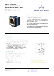
7.2 Digital photography<br />
The connection of digital single lens reflex<br />
cameras is done by a sensor fitted photo<br />
adaptation and camera suited T2 adaptation<br />
ring. Three different photo adaptation 1,0x;<br />
1,6x; 3,2x are available.<br />
For a maximum object field following optimal<br />
combinations between sensor size an photo<br />
adaptation are recommend:<br />
Full frame 24,0mm x 36,0 mm → 3,2x<br />
APS-C 14,8mm x 22,2mm → 1,6x<br />
Four Thirds 13,5mm x 18,0mm → 1,0x<br />
pic.13: photo adaptations 3,2x; 1,6x; 1,0x
8. TV – Transfer<br />
8.1. TV – Transfer over Photo-/TV tube<br />
For the TV transfer is only a Photo-/TV tube and<br />
a TV with camera and a monitor adjustment are<br />
needed. For the right adaptation of the image<br />
detail of the camera in comparison to the image<br />
in the eyepiece there are four different TVadapter<br />
available with magnification factor<br />
0,3x ; 0,4x ; 0,4xWF ; 0,63x ; 1x and 1,6x.<br />
The Photo-/TV tube is set for adjustment on the<br />
microscope centre section. At the upper exit of<br />
the Photo-/TV tube will be mount the TV adapter<br />
and above the TV adapter will be set a video<br />
camera (in most cases the thread is c-mount)<br />
All TV-adapter will be aligned factory-made at<br />
the delivery. In normal case you don’t have to<br />
change nothing. In case you don’t have a clear<br />
picture you have to follow the instructions at<br />
points 8.1.1 and 8.1.2.<br />
8.1.1 The TV-adapter 1x comes in two parts<br />
which will be clamped with two screws. The<br />
lower part will be set directly on the Photo-/TV<br />
tube, the upper part will be set on the T2adapter<br />
. Both parts will be add together and<br />
will be adjust against each other at a good<br />
aligned microscope with smallest magnification<br />
factor until there is a clear and sharpen picture<br />
on the monitor. Now you have to align the<br />
camera itself (left and right side of a picture) and<br />
the screws will be tighten.<br />
19<br />
pic.14: Tv – adaptation 0,3x … 1,6x<br />
pic.15: phototube with Tv adaptation 0,63x<br />
and camera<br />
8.1.2 You have to do the same steps for the<br />
TV-adapter 0,3x ; 0,4x ; 0,4x WF ; 0,63x and<br />
1,6x (analogous in comparison to the TVadapter<br />
1x)
9. Illumination<br />
9.1. 3W – LED Transmitted light<br />
For a research of transmitted objects it can be<br />
helpful to observe the objects not only in incident<br />
light illumination. The use of transmitted light<br />
illumination is good to define structures much<br />
more better.<br />
pic.16: stage carrier with object guide and<br />
condenser for transmitted light<br />
Please note: The 3W-LED transmitted light can<br />
be only used in combination with stage carrier<br />
with object guide.<br />
pic.17: optics for transmitted light (placed in the<br />
stand)<br />
Further it is necessary to use a condenser. The<br />
condenser comes with a wide field lens and an<br />
aperture stop.<br />
20<br />
9.2. Oblique incident light (dark field)<br />
For a lot of objects dark field will most suited –<br />
contours have a high contrast; finest structures,<br />
reliefs, damages on surfaces are much more<br />
better visible than with bright field illumination.<br />
The equipment comes with an articulated arm<br />
and a 3W-LED incident light illuminator,<br />
focusable and a transformer for the 3W-LED<br />
illumination, adjustable. This illumination is suited<br />
for the objectives 5x; 10x; 20x.<br />
pic.18: oblique incident light
10. Stages<br />
Gliding stage, stage carrier with object guide<br />
and stage carrier with rotary stage can be<br />
changed quickly without any problems about a<br />
changer.<br />
10.1. Gliding stage<br />
The gliding stage offers the possibility of a free<br />
positioning of the object within a diameter of 40<br />
mm can be done with the precise gliding stage.<br />
The maximum height of the specimen is 30 mm.<br />
pic.19: gliding stage<br />
10.2. Stage carrier with object guide<br />
The object-guide allows a x-y- adjustment in<br />
range of 76 x 26 mm. The maximum height of<br />
the specimen is 40 mm.<br />
pic.20: stage carrier with object guide<br />
21<br />
10.3. Stage carrier with rotary stage<br />
The stage carrier with rotary stage is usable for<br />
the research of translucent <strong>pol</strong>arizing objects.<br />
The stage allows the determination of axial<br />
attitudes from birefringent objects. The maximum<br />
height of the specimen is 35 mm.<br />
pic.21: stage carrier with rotary stage<br />
10.4. Magnet spherical stage<br />
The magnet spherical stage is suited for probe<br />
positioning and tilting the object to a max. 45°<br />
angle. The object clamp is done by small<br />
magnet mounts. To avoid slipping the spherical<br />
stage is also magnetic mounted.<br />
pic.22: magnet spherical stage
10.5. Depth measurement<br />
10.5.1 Depth measurement (z-axis) with the<br />
combination drive is done by reading the scale<br />
on the drive knob during fine focussing between<br />
the two or more certain object levels. The scale<br />
is divided into 100 units. When the fine drive is<br />
used One graduation mark equals 2,8 µm. The<br />
range of depth measurement with combination<br />
drive is 0,288 mm.<br />
To avoid measuring errors caused by the<br />
reversal error of the drive (combination and<br />
coaxial coarse and fine drive) just measure the<br />
object points (object levels) from only one<br />
direction.<br />
10.5.2 Depth measurement with the coaxial<br />
coarse and fine drive is almost the same as with<br />
the combination drive. The scale is divided into<br />
50 units. When the fine drive is used one<br />
graduation mark equals 2,0 µm. The range of<br />
depth measurement with coaxial is limited to<br />
adjustable range of coarse drive (20 mm).<br />
10.5.2 Depth measurement can also be done<br />
with help of a analogue or digital dial indicator<br />
gauge which is mounted on the side. The gauge<br />
sensor cone is connected to the stage.<br />
pic. 23: indicator gauge for depth measurement<br />
22
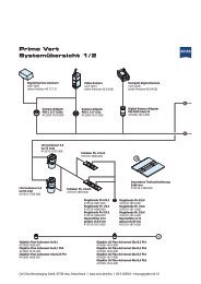
11. System overview<br />
23
12. Complaints, Warranty<br />
Obvious defects must be notified in writing<br />
without delay, but at the latest within one week<br />
of receipt of the goods, together with a<br />
declaration of what was found. Failure to inspect<br />
the goods counts as an unreserved acceptance<br />
of their compliance with the conditions. The<br />
warranty period is 2 years.<br />
We reserve the right for the product to differ<br />
from our brochures as a result of any<br />
improvements or alternations for other reasons.<br />
Such alternations do not oblige us to make a<br />
special announcement. No liability is accepted<br />
for printing errors.<br />
24<br />
<strong>Mikroskop</strong> <strong>Technik</strong> <strong>Rathenow</strong> GmbH<br />
Grünauer Fenn 40<br />
Germany-14712 <strong>Rathenow</strong><br />
Phone: +49 (0)3385 53710<br />
Telefax: +49 (0) 3385 537122<br />
Internet: http://www.askania.de<br />
e-mail: mikro.ra@askania.de<br />
date: May 2009