ISK 74 - ASO Safety
ISK 74 - ASO Safety
ISK 74 - ASO Safety

Create successful ePaper yourself
Turn your PDF publications into a flip-book with our unique Google optimized e-Paper software.
7.3 Versions and mechanical mounting<br />
Version SK <strong>74</strong>-30<br />
PCB version<br />
Version SK <strong>74</strong>-31<br />
Pol��carbonate housing with screw connections for on-wall mounting in harsh environments.<br />
The switching unit is to be professionall�� mounted at a suitable location. After removing the cover,<br />
the housing can be mounted with four screws.<br />
The switching unit ma�� be mounted in an�� orientation. To prevent moisture penetration, it should,<br />
however, be installed so that the cable conduits point downward.<br />
Version SK <strong>74</strong>-33<br />
Snap-on-rail version for mounting on 35 mm DIN rails in the switching box.<br />
8. Connecting the device<br />
8.1 Prerequisites<br />
• The suppl�� voltage used for the <strong>ISK</strong> <strong>74</strong> must compl�� with the requirements for safet�� low voltage<br />
(SELV).<br />
• Cables installed outdoors or outside of the switching cabinet must be protected appropriatel��.<br />
• The protection class specified for this device is only ensured if the supply lines have been properly<br />
clamped to the screw connections.<br />
2 3 24V AC/DC PE L1 N<br />
ANSMIT<br />
TOP<br />
osing<br />
TOP<br />
osing<br />
24 V<br />
230 V<br />
STATIONARY 1 2 3<br />
Opening Closing TRANSMIT<br />
STATIONARY 1 2 3<br />
Opening Closing TRANSMIT<br />
STOP STOP<br />
Opening Closing<br />
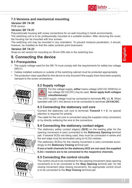
8.2 Supply voltage<br />
For the voltage suppl��, either mains voltage (230 V AC 50/60 Hz) or<br />
low voltage (24 V AC/DC) ma�� be used. Never apply both voltages<br />
simultaneously!<br />
The 230 V suppl�� voltage must be connected to terminals PE, L1, N. When<br />
operated with 24 V, the device is to be connected to terminals 24 V AC/DC.<br />
8.3 Connecting the stationary coil core<br />
Connect the stationar�� coil core to terminals Transmit 1 + 2; no special<br />
attention is required for polarit��.<br />
The cable for the coil core is connected using the supplied crimp connectors<br />
or b�� directl�� soldering the wire to the connectors.<br />
8.4 Connecting the stationary contact edges<br />
The stationar�� safet�� contact edge(s) (SCE) on the leading pillar for the<br />
opening movement is (are) connected to the Stationary Opening terminal<br />
pair. If several SCEs are being used, the�� must be connected in series and<br />
the end edge must be terminated using an 8.2 kW resistor.<br />
The stationar�� SCE(s) for the closing movement is (are) connected accordingl��<br />
to the Stationary Closing terminal pair.<br />
If one or both channels for the stationary SCE are not used, the supplied<br />
8.2 kW resistors are to be connected to the respective channels.<br />
8.5 Connecting the control circuits<br />
The control circuit to be monitored for the opening movement (stop-opening<br />
movement) is to be connected to the Stop Opening terminal pair; for the<br />
closing movement (stop closing movement), the appropriate control circuit<br />
is to be connected to the Stop Closing terminal pair.<br />
English<br />
17