455 D Control Board - FAAC USA
455 D Control Board - FAAC USA
455 D Control Board - FAAC USA

You also want an ePaper? Increase the reach of your titles
YUMPU automatically turns print PDFs into web optimized ePapers that Google loves.
1. <strong>455</strong> D CONTROL BOARD<br />
1.1 <strong>455</strong> D <strong>Control</strong> <strong>Board</strong> Warnings<br />
Important: Before attempting any work on the control<br />
board (connections, maintenance), always turn off<br />
power.<br />
Please refer to Chapter 16 for AC power wiring<br />
guidelines<br />
1.2. Technical Specifications<br />
Power Supply 115 V~ ± 10% or 230 V~ +6% -10% 50/60 Hz<br />
Absorbed Power 10 W<br />
Motor Max. Load 800 W<br />
Accessories Max. Load 0,5 A<br />
Electric Lock Max. Load 15 VA<br />
Ambient Operating Temperature Range -4°F to +131°F<br />
Protection Fuses 2 (see Fig. A)<br />
Function Logics: Semi-automatic / Automatic / Safety Devices /<br />
“Stepped” Semi-automatic / “Stepped” Automatic / “Stepped” Safety<br />
Devices / Semi-automatic B / Dead-man C<br />
Opening/Closing Time Programmable (from 0 to 120 s)<br />
Pause Time Programmable (from 0 to 4 min.)<br />
Closing Leaf Delay Programmable (from 0 to 4 min.)<br />
Opening Leaf Delay 2 s (can be excluded)<br />
Thrust Force: Adjustable on 50 levels for each motor<br />
Terminal <strong>Board</strong> Inputs: Open / Open Free Leaf / Stop / Limit-switch<br />
Opening Safety Devices / Closing Safety Devices / Power Supply +<br />
Earth.<br />
Terminal <strong>Board</strong> Outputs: Flashing Lamp / Motors / 24 VDC Accessories<br />
Power Supply / 24 VDC Indicator-Light / Fail Safe / 12 VAC<br />
Electric Lock Power Supply<br />
Programmable Functions: Logic / Pause Time / Thrust Force / Torque<br />
at Initial Thrust / Opening and Closing Leaf Delay / Reversing Stroke<br />
/ Over-Pushing Stroke / Indicator-Light / Pre-Flashing / Electric Lock /<br />
Fail Safe / Safety Devices Logic / Assistance Request / Detection Time<br />
of Obstacle or Contact Point<br />
Learning Function: Simple or complete work time learning, with or<br />
without Limit-switch and/or Gatecoder.<br />
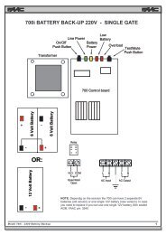
1.3 Electric Connections<br />
230 VAC<br />
50 Hz<br />
or<br />
115 VAC<br />
60 Hz<br />
NB: Capacitors are supplied with the operator.<br />
<strong>455</strong> D <strong>Control</strong> <strong>Board</strong><br />
BLUE<br />
BLUE<br />
VAC MAX.<br />
60W<br />
OPEN A<br />
OPEN B<br />
STOP<br />
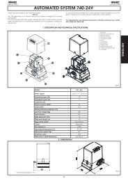
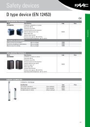
1.4. <strong>455</strong> D Layout and Components<br />
J3<br />
J3<br />
F1<br />
PE N L<br />
MAIN<br />
F1<br />
J4<br />
F2<br />
J4 J1<br />
1 2 4 5 6 7 8<br />
COM OP<br />
M1 COM OP<br />
9 10 11 12 13 14 15 16 17 18 19 20 21<br />
A B<br />
M2 CL LAMP<br />
STP CL OP - - -<br />
+ + -TX<br />
OPEN<br />
FSW<br />
+24V FSW W.L. LOCK<br />
F2<br />
OP_A<br />
STOP<br />
OP_B<br />
J1<br />
FSWOP<br />
DL<br />
FCA1<br />
FSWCL FCA2<br />
+ – F<br />
DL SIGNALLING AND PROGRAMMING DISPLAY<br />
J1 LOW VOLTAGE TERMINAL BLOCK<br />
J2 CONNECTOR FOR RP RECEIVER<br />
J3 AC POWER SUPPLY TERMINAL BLOCK<br />
+<br />
–<br />
F<br />
FCC1<br />
FCC2<br />
J5<br />
J6<br />
J5<br />
22 23 24 25<br />
FCA1<br />
FCC1<br />
J6<br />
FCA2<br />
J2<br />
Figure A<br />
J4 MOTORS AND FLASHING LAMP CONNECTION TERMINAL BLOCK<br />
J5 INDICATOR-LIGHT AND ELECTRIC LOCK TERMINAL BLOCK<br />
J6 LIMIT-SWITCH AND GATECODER TERMINAL BLOCK<br />
F1 MOTORS AND TRANSFORMER PRIMARY WINDING<br />
FUSE (F 5A - 230V) (F 10A - 115V)<br />
F2 LOW VOLTAGE AND ACCESSORIES FUSE (T 800mA)<br />
F “F” PROGRAMMING PUSH-BUTTON<br />
– “–” PROGRAMMING PUSH-BUTTON<br />
+ “+” PROGRAMMING PUSH-BUTTON<br />
For connection<br />
of the photocells<br />
and safety<br />
devices, see<br />
Section 13.4.1.<br />
24 VDC<br />
3W<br />
12 VAC<br />
LIMIT-SWITCH<br />
OR GATECODER<br />
FCC2<br />
Figure B<br />
FCC2<br />
3