PDF Presentation - faculty.ait.ac.th - Asian Institute of Technology
PDF Presentation - faculty.ait.ac.th - Asian Institute of Technology
PDF Presentation - faculty.ait.ac.th - Asian Institute of Technology

Create successful ePaper yourself
Turn your PDF publications into a flip-book with our unique Google optimized e-Paper software.
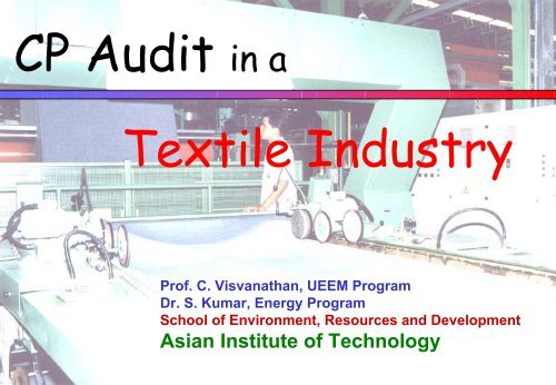
CP Audit in a<br />
Visu/Kumar<br />
Textile Industry<br />
Pr<strong>of</strong>. C. Visvana<strong>th</strong>an, UEEM Program<br />
Dr. S. Kumar, Energy Program<br />
School <strong>of</strong> Environment, Resources and Development<br />
<strong>Asian</strong> <strong>Institute</strong> <strong>of</strong> <strong>Technology</strong><br />
1
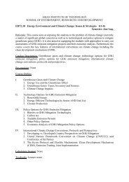
CP Audit in a Textile Industry<br />
ZEBRA Industry Co., Ltd.: Medium size f<strong>ac</strong>tory in Samutprakarn<br />
Products: Knitted fabrics, dyed clo<strong>th</strong> and yarns<br />
Two main sections: Knitting and dyeing<br />
Office and<br />
Residence<br />
Visu/Kumar<br />
Municipal<br />
Workshop<br />
Yarn<br />
Dyeing<br />
Section<br />
Knitting Section<br />
Boiler<br />
Office<br />
LAB Dyeing<br />
Finishing<br />
Section<br />
Gate<br />
1<br />
2<br />
3<br />
4<br />
WW to<br />
Klong<br />
5<br />
6<br />
7<br />
1. Setting pond<br />
2. Aerated pond 2<br />
3. Aerated pond 1<br />
4. Equalization pond<br />
5. Oxidation pond 3<br />
6. Oxidation pond 2<br />
7. Oxidation pond 1<br />
2
Step 1: Define <strong>th</strong>e Objectives and Scope <strong>of</strong> Auditing<br />
Objectives:<br />
Visu/Kumar<br />
• Upgrade and modify <strong>th</strong>e existing treatment processes, to<br />
obtain higher removal efficiency <strong>of</strong> COD and color<br />
• Adopt a long term economically viable Cleaner Production<br />
appro<strong>ac</strong>h, which essentially focuses into <strong>th</strong>e possibility <strong>of</strong> waste<br />
prevention and reduction at <strong>th</strong>e production stage, ra<strong>th</strong>er <strong>th</strong>an<br />
concentrating on <strong>th</strong>e end <strong>of</strong> <strong>th</strong>e line pollution control<br />
• Investigate energy conservation measures<br />
Scope:<br />
What should be <strong>th</strong>e scope <strong>of</strong> <strong>th</strong>e study??<br />
• Focus mainly on <strong>th</strong>e dyeing and finishing section<br />
3
Step 2: Formation <strong>of</strong> Audit Team<br />
Name Designation<br />
Dr. C. Visvana<strong>th</strong>an Pr<strong>of</strong>essor, Environmental Engineering Program,<br />
Visu/Kumar<br />
Audit Team Advisor<br />
Dr. Kumar Associate pr<strong>of</strong>essor, Energy program<br />
Mr. Ramon C. de Mesa<br />
Ms. Mendeluz B.<br />
Mr. T. Pichitchai Plant Manager<br />
Mrs. N.T.Lien Ha Research Associate<br />
Mr. D.Q. Tuan Research Associate<br />
Ms. Yamuana Alles Dye Master<br />
Mr. Ashish Arora Plant Engineer<br />
Mr. T. Visu<strong>th</strong> Plant Engineer<br />
4
Step 3: Plant Walk Through: Understanding <strong>th</strong>e Dyeing Process<br />
Visu/Kumar<br />
Start plant walk<strong>th</strong>rough<br />
After plant walk<strong>th</strong>rough, what can you observe?<br />
Observations:<br />
• Leaks/overflow in <strong>th</strong>e production area<br />
• Bad Housekeeping at dye kitchen<br />
•<br />
• Bad insulation(steam pipes)<br />
• Bad smell from WWTP/Products plant<br />
•<br />
Higher emission from <strong>th</strong>e boiler<br />
Layout problems<br />
•Bo<strong>th</strong> boilers working; no metering <strong>of</strong> steam<br />
•Flue gas measurement not continuous<br />
What Else…??<br />
5
Step 4: Listing <strong>of</strong> Unit Operations<br />
Clo<strong>th</strong> Dyeing Section<br />
Visu/Kumar<br />
Ble<strong>ac</strong>hing<br />
Scouring<br />
Washing<br />
Filling<br />
Dyeing<br />
Washing<br />
Filling<br />
Fixing<br />
Drying<br />
What else??<br />
6
Visu/Kumar<br />
H 2 O, L:R = 10:1<br />
NaOH, 1%W/W<br />
H 2 O 2 , 2%<br />
Detergent, 0.8%<br />
Sequestering, 1%<br />
OBA (Optical Brightening Agent), 0.3%<br />
H 2 O, 60 c<br />
Formic <strong>ac</strong>id, 0.2%<br />
H 2 O 98 0 C, L:R = 10:1<br />
NaCl, 6.5%<br />
Formic <strong>ac</strong>id 0.5%<br />
Dyestuff: disperse 0.012%<br />
Amonium sulphate 0.65%<br />
Dispersing Agent 1.0%<br />
Batch Operation<br />
H 2 O 40 0 C<br />
H 2 O 40 0 C<br />
H 2 O 40 0 C<br />
H 2 O 40 0 C<br />
H 2 O 60 0 C<br />
Fixing Agent 0.15%<br />
H 2 O L:R = 1:1<br />
PVAC 10%<br />
S<strong>of</strong>tener 1%<br />
(non-ionic)<br />
H 2 O 60 0 C, L:R = 10:1<br />
Soaping Agent 0.15%<br />
Step 5: Process Flow Diagram<br />
Gray Clo<strong>th</strong><br />
Ble<strong>ac</strong>hing/Scouring Fluorescent whitening<br />
Washing 1<br />
Washing 2<br />
Filling 1<br />
Clo<strong>th</strong> Dyeing<br />
Washing 3<br />
Washing 4<br />
Filling 2<br />
Fixing<br />
Drying<br />
Resin Finishing Flores whitening<br />
Drying<br />
Curing<br />
Rolling up Plainting Down<br />
What else<br />
is missing<br />
7
Step 6: M<strong>ac</strong>hine Layout <strong>of</strong> <strong>th</strong>e Dyeing-Finishing Section<br />
R: Rapid Winch<br />
W: Washing M<strong>ac</strong>hine<br />
Visu/Kumar<br />
Finishing<br />
Finishing<br />
Drier 2<br />
Finishing<br />
Finishing<br />
Dryer1<br />
HT: High Temperature Winch<br />
: Sampling Site<br />
: Wastewater channels<br />
: Wastewater sump<br />
Screen<br />
Printing<br />
To Equalization Pond<br />
Samp. Site 4<br />
Sump<br />
Samp. Site 3<br />
WS3 WS2 WS1<br />
RW6<br />
RW5<br />
RW8<br />
RW7<br />
RW1<br />
RW9<br />
RW4<br />
RW3<br />
RW2<br />
HT3 HT2 HT1<br />
Samp.<br />
Site 3<br />
Samp. Site 3<br />
To Oxidation Pond<br />
8
Step 7: Review <strong>th</strong>e WWTP<br />
To Klong<br />
Visu/Kumar<br />
Activated<br />
Carbon<br />
Sand filter<br />
Settling pond<br />
(400 m 2 )<br />
Aerated pond 2<br />
(400 m 2 )<br />
Aerated pond 1<br />
(400 m 2 )<br />
Wetland<br />
Oxidation pond 1 (3000 m 2 )<br />
Oxidation pond 2 (2000 m 2 )<br />
Oxidation pond 3 (2500 m 2 )<br />
Equalization<br />
Pond (400 m 2 )<br />
Wastewater from Stentor<br />
Schematic Diagram <strong>of</strong> <strong>th</strong>e Wastewater Treatment Plant<br />
Wastewater from sampling site 1<br />
9
Step 8: Material Consumption for <strong>th</strong>e Clo<strong>th</strong> and Yarn Dyeing Sections<br />
Material Recorded<br />
Clo<strong>th</strong> (dry, kg/d) 12,000<br />
Yarn (dry, kg/d) 2,000<br />
Fresh Water (m 3 /d) 565<br />
Dyestuff (kg/d) 2.25<br />
Auxiliary Chemicals (kg/d) 3,068<br />
-NaOH 120<br />
-H2O2 240<br />
-Detergent 88<br />
- Sequestering Agent 120<br />
- NaCl 980<br />
-Formic <strong>ac</strong>id 84<br />
- Ammonium sulphate(AMS) 66<br />
- Soaping Agent 30.4<br />
-Fixing Agent 219.2<br />
- Polyvinyl<strong>ac</strong>etate(PVAC) 1,200<br />
-S<strong>of</strong>tener 120<br />
- Steam 142,000<br />
Visu/Kumar<br />
What is<br />
missing<br />
10
Step 9:<br />
Ground water Treated water<br />
s<strong>of</strong>tening)<br />
Visu/Kumar<br />
Domestic use<br />
Industrial use<br />
Boiler<br />
Yarn Dyeing section<br />
Clo<strong>th</strong> Dyeing section<br />
Knitting<br />
11
Step 10: Benchmarking (Comparison <strong>of</strong> wastewater generation)<br />
Visu/Kumar<br />
Type <strong>of</strong><br />
processes<br />
Scouring,<br />
Ble<strong>ac</strong>hing,<br />
Dyeing and<br />
Washing<br />
Electricity<br />
Consumption<br />
Type <strong>of</strong><br />
product<br />
Cotton Yarn 0.15<br />
UNIDO<br />
m 3 /Kg<br />
0.3-12.6<br />
MWh/ton<br />
Energy Consumption…???? …. > ….. 42% %<br />
Measured<br />
m 3 /Kg<br />
0.05<br />
18 MWh/ton<br />
Or you can use COD as ano<strong>th</strong>er indicator (kg/ton)<br />
12
R: Rapid Winch<br />
W: Washing M<strong>ac</strong>hine<br />
Visu/Kumar<br />
Stenter 1<br />
Stenter 2<br />
Drier 2<br />
Stenter 3<br />
Stenter 4<br />
Dryer1<br />
HT: High Temperature Winch<br />
: Sampling Site<br />
: Wastewater channels<br />
: Wastewater sump<br />
To Equalization Pond<br />
Screen<br />
Printing<br />
Samp. Site 4<br />
Sump<br />
Samp. Site 3<br />
WS3 WS2 WS1<br />
RW6<br />
RW5<br />
RW8<br />
RW7<br />
RW1<br />
RW9<br />
RW4<br />
RW3<br />
RW2<br />
HT3 HT2 HT1<br />
Step 11: Sampling plan<br />
Samp.<br />
Site 3<br />
Samp. Site 3<br />
To Oxidation Pond<br />
13
Step 12: Overall Water Consumption Record<br />
Section<br />
Visu/Kumar<br />
Fresh<br />
water in<br />
To ETP Recycled Loss<br />
Domestic 30 30 0<br />
Boilers 142 N/A- 0<br />
Yarn<br />
Dyeing<br />
Clo<strong>th</strong><br />
Dyeing<br />
O<strong>th</strong>er<br />
(knitting)<br />
80 80 0<br />
485 29 0<br />
10 N/A 0<br />
Cooling 28 N/A<br />
Total 775 539 0<br />
Output: Wastewater = 539 m3 (This value was measured at <strong>th</strong>e WWTP)<br />
Mass Balance:?? (775 -539) / (775) * 100 = 30.45%<br />
OK<br />
or not<br />
0<br />
142<br />
0<br />
56<br />
-<br />
228<br />
14
Step 13: Overall Water Consumption Record<br />
Visu/Kumar<br />
INPUT<br />
Boiler (142 m3)<br />
18%<br />
Knitting<br />
(10 m3)<br />
1%<br />
Domestic Usage<br />
(30 m3)<br />
4%<br />
Water Supply<br />
(775 m 3 /day)<br />
Yarn Dyeing<br />
(80 m3) 10%<br />
Cooling (28 m3)<br />
4%<br />
Clo<strong>th</strong> Dyeing<br />
(485m3)<br />
63%<br />
15
Step 14: Clo<strong>th</strong> Dyeing Wastewater 485 m 3<br />
Stentor WW<br />
6%<br />
Visu/Kumar<br />
Losses<br />
12%<br />
Fixing &<br />
Washing<br />
57%<br />
Ble<strong>ac</strong>hing<br />
12%<br />
Dyeing<br />
13%<br />
16
Step 15: Material Balance: Sector Level<br />
Total Input: 485 m 3<br />
Output<br />
Visu/Kumar<br />
Section m 3 /d<br />
Ble<strong>ac</strong>hing : 60<br />
Dyeing : 64<br />
Fixing and Washing : 274<br />
Stentor : 30<br />
TOTAL : 429<br />
Percentage deficit : (485 ….?? -429) / 485 * 100 % : 11.5 % < 20%<br />
Difference = 56 m 3 : due to evaporation losses / pick up on <strong>th</strong>e clo<strong>th</strong>.<br />
OK<br />
17
Step 16: Unit Level Material Balance<br />
Percent Loss:<br />
Visu/Kumar<br />
Tie Compound COLOR : ADMI<br />
1 ADMI : 1 mg/L Dye<br />
Input:<br />
(At dyeing unit)<br />
Jet Dyeing : 2,040 g/d<br />
Dyeing<br />
Outputs:<br />
Washing 3 : 325 g/d<br />
Washing 4 : 275 g/d<br />
Fixing : 25 g/d<br />
Clo<strong>th</strong> : 1,400 g/d<br />
TOTAL : 2,025 g/d<br />
..?? (2040-02025)/(2040)*100 = 0.75 % How Excellent is it..?<br />
Total Waste<br />
(% Fixing <strong>of</strong> Dye) = 68%<br />
Industry Norms : ≥ 75%<br />
Which Item is not efficient..? Washing 3<br />
18
Step 17: Current Level <strong>of</strong> Water Reuse - Recycling<br />
Step 18: Quantifying <strong>th</strong>e Process Outputs<br />
Major:<br />
Visu/Kumar<br />
Clo<strong>th</strong> Dry : 12,000 kg/d<br />
Wastewater : 539 m 3 /d<br />
Solid waste (including sludge) : 820 kg/d<br />
19
Step 19:<br />
Thousands<br />
16<br />
14<br />
12<br />
10<br />
8<br />
6<br />
4<br />
2<br />
0<br />
Visu/Kumar<br />
13.6<br />
3.5<br />
4<br />
W.W. x 0.1m3 COD Color x 0.5 ADMI BOD<br />
1.9<br />
1.5<br />
0.8 0.8 0.8<br />
1<br />
0.8 0.8<br />
0.8 0.8<br />
0.5<br />
0.7<br />
0.4<br />
0.5<br />
0.25<br />
0 0 0 0.05 0 0<br />
Ble<strong>ac</strong>hing Neutralizing Dyeing Washing 1 Fixing Washing 2 Stentor<br />
0.3<br />
7.3<br />
1<br />
PVAC<br />
3<br />
20
Step 20: Pollution Load per day on ETP<br />
100<br />
90<br />
80<br />
70<br />
60<br />
50<br />
40<br />
30<br />
20<br />
10<br />
0<br />
Visu/Kumar<br />
7<br />
Flow<br />
COD Load<br />
BOD Load<br />
1 1<br />
20<br />
2 2<br />
80<br />
96<br />
95<br />
8<br />
18 18<br />
Domestic Yarn Dyeing Clo<strong>th</strong> Dyeing Stenter<br />
21
Step 21: COD / BOD Removal Efficiency <strong>of</strong> <strong>th</strong>e ETP<br />
Units Flowrate (m COD Removal BOD Removal<br />
Efficiency<br />
In Out Loss In Out Efficiency in out<br />
3 /d)<br />
(mg/L)<br />
(%)<br />
Visu/Kumar<br />
(mg/L)<br />
Filters 250 250 0 190 185 2.6 36 28 22.2<br />
Settling Pond 254 250 4 235 190 20.4 52 36 31.9<br />
Aerated Pond 2 258 254 4 271 235 14.6 122 52 58.0<br />
Aerated Pond 1 262 258 4 900 271 70.3 381 122 31.5<br />
Wetland Pond 539 262 277 2650 900 83.5 1174 381 84.2<br />
Equalization Pond 30 30 0 5800 1240 78.6 2628 338 87.1<br />
Total 289<br />
Loss in Pond: 277 m 3 /d<br />
How Much ???<br />
Why?<br />
(%)<br />
22
Step 22: Performance <strong>of</strong> Current ETP<br />
Filters<br />
Out 250 m 3<br />
COD 190<br />
Out 250 m 3<br />
COD 190<br />
Visu/Kumar<br />
Setting<br />
Pond<br />
Wetland Area<br />
Loss due to infiltration and<br />
evaporation 277 m 3 (51.3%)<br />
20.4% COD<br />
31.9% BOD<br />
Out 254 m 3<br />
COD 235<br />
14.6% COD<br />
58.0% BOD<br />
Aerated Pond<br />
2 wi<strong>th</strong> 4<br />
aerators<br />
Loss 45.8%<br />
Out 258 m 3<br />
COD 271<br />
70.3% COD<br />
Aerated<br />
Pond 1<br />
83.5% COD<br />
84.2% BOD<br />
31.5% BOD<br />
Out 30 m 3<br />
78.6% COD<br />
87.1% BOD<br />
COD 1240<br />
Equalization<br />
Pond<br />
Input 539 m 3<br />
COD 2650 mg/L<br />
Out 262 m 3<br />
COD 900<br />
In 30 m 3<br />
COD 5800<br />
23
Step 23: Major Sources <strong>of</strong> Wastewater<br />
Visu/Kumar<br />
Ble<strong>ac</strong>hing / dyeing and finishing stage<br />
Wash water + Steam condensate<br />
Wastewater and COD Load on ETP<br />
24
R = Rapid Winch<br />
W = Washing M<strong>ac</strong>hine<br />
HT = High Temperature Winch<br />
CTP = Chemical Treatment Plant<br />
Visu/Kumar<br />
Sampling site<br />
Wastewater sump<br />
HT3 HT2 HT1<br />
Samp.<br />
Site 3<br />
RW3<br />
Less-polluted Wastewater channels<br />
Polluted Wastewater Channel<br />
RW4<br />
RW2<br />
RW5<br />
RW1<br />
RW7<br />
RW6<br />
RW8<br />
WS3 WS2 WS1<br />
RW9<br />
Sump<br />
1<br />
2<br />
3<br />
CTP<br />
Step 24: Proposed Layout <strong>of</strong> Segregated Effluent Channels and<br />
Modification <strong>of</strong> <strong>th</strong>e Current ETP.<br />
4<br />
25
Step 25:<br />
Visu/Kumar<br />
Total dye Purchased : 2.25<br />
Total Dye Used : 2.04<br />
Difference in handling : ..??? %<br />
9.33%<br />
House keeping Records<br />
26
Option 1: Polyvinyl<strong>ac</strong>etate (PVAC)<br />
Visu/Kumar<br />
Used for resin finishing after dyeing process<br />
Daily consumption = 1200 kg/d (PVAC)<br />
Organic compound = compound volatile<br />
Expensive = 500 Baht / kg<br />
High BOD Load<br />
Smell in <strong>th</strong>e drying chamber (OHS)<br />
Most <strong>of</strong> <strong>th</strong>e ‘PVAC’ which is not att<strong>ac</strong>hed to <strong>th</strong>e clo<strong>th</strong> is removed<br />
at <strong>th</strong>e drying chamber.<br />
Moisture content : at <strong>th</strong>e finishing : 95%<br />
at <strong>th</strong>e drying : 7.5%<br />
10% PVAC Add a v<strong>ac</strong>uum evaporator<br />
27
Option 2: Steam Condensate<br />
Visu/Kumar<br />
Currently discharged as a Waste water at a<br />
temperature <strong>of</strong> 75 0 C,<br />
Measured volume = 120 m 3 / d<br />
Condensate Recovery System<br />
28
Fabric<br />
Visu/Kumar<br />
Boiler<br />
Underground cooling<br />
water storage<br />
Fresh boiler water IN<br />
Heat Exchanger<br />
Condensate discharge<br />
Fresh Cooling water IN<br />
Finishing Dip<br />
Drying chamber<br />
Fresh finishing<br />
chemicals<br />
29
Fabric<br />
Boiler<br />
Underground cooling<br />
water storage<br />
Visu/Kumar<br />
Boiler water<br />
makeup<br />
Heat Exchanger<br />
Condensate recovery unit<br />
Fresh Cooling water IN<br />
Finishing Dip<br />
EVAC suction system<br />
Drying chamber<br />
Fresh finishing<br />
chemicals<br />
30
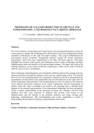
Option 3: Recovery <strong>of</strong> Kerosene used in Textile Printing<br />
Brief Description :<br />
Kerosene is used as print paste <strong>th</strong>ickener:<br />
Visu/Kumar<br />
120-140 c : recovery chamber<br />
Loss <strong>of</strong> Kerosene at Different Stages <strong>of</strong> Printing<br />
78%<br />
1%<br />
4%<br />
12%<br />
5%<br />
Before entry into Drier<br />
On Blankets, Screen &<br />
Drained waste<br />
On Curing m<strong>ac</strong>hine<br />
Remains on fabric<br />
Atmospheric release from<br />
Drier<br />
Number <strong>of</strong> Trials 10<br />
Total kerosene used for preparation <strong>of</strong> print paste 1870 litres<br />
Quantity <strong>of</strong> kerosene evaporated at Dryer 1402 l itres<br />
Kerosene vapour recovered <strong>th</strong>ro’ plant 1100 litres<br />
Percentage <strong>of</strong> kerosene recovery from printing Dryer 78.5%<br />
Percentage <strong>of</strong> Kerosene recovered based on total<br />
consumption<br />
58.8%<br />
31
Visu/Kumar<br />
Boiler is a very common heat exchange equipment<br />
Analyze <strong>th</strong>e data<br />
→ Air used →<br />
Theoretical- Input<br />
Actual- Output<br />
→ Excess → Temp↓<br />
O<strong>th</strong>er Cap<strong>ac</strong>ity<br />
(Blower)<br />
→ Efficiency<br />
Important (2 Phase)<br />
32
Visu/Kumar<br />
3 Pass Coal Fire Boiler<br />
Steam Out<br />
Fire Tube Steam Boiler<br />
Steam Out<br />
Smoke St<strong>ac</strong>k<br />
Smoke St<strong>ac</strong>k<br />
Water In<br />
Water Tube Steam Boiler<br />
33
Visu/Kumar<br />
Plant Walk<strong>th</strong>rough: Boiler Data<br />
1. Flue gas % (O 2 ) = 8.2%<br />
Temperature = 310 0 C<br />
2. Fuel = 750 kg/h<br />
(C = 85.9%, H = 11.8%, S = 2%,…. )<br />
3. Oil Heater = 8 kW<br />
Oil Pump = 1 kW<br />
4. Fan = 30 kW<br />
5. Pumps = 1 kW<br />
6. Water Feed = 10 m 3 / h<br />
7. Blow Down = 0.6 m 3 / h<br />
8. Steam Pressure = 10 bar<br />
Temperature = 180 0 C<br />
9. Convection & Radiation Loss = 50,000 kJ/h<br />
34
Boiler is a very common heat exchange equipment.<br />
Visu/Kumar<br />
35
Visu/Kumar<br />
Boiler Analysis: Combustion<br />
A. Calculation <strong>of</strong> Theoretical Air requirement:<br />
Required data (Fuel constituents):<br />
C - 85.9% H - 11.8% S - 2%<br />
H 2 O - 0.3% Ash - 0.008%<br />
Chemical equations<br />
C + O 2 CO 2<br />
S + O 2 SO 2<br />
2H 2 + O 2 2H 2 O<br />
(2) (1)<br />
1 mole <strong>of</strong> air = 0.21 moles <strong>of</strong> O 2 + 0.79 moles <strong>of</strong> N 2<br />
∴ 1 mole <strong>of</strong> O 2 = 0.79/0.21 = 3.76 mole <strong>of</strong> N 2<br />
36
Visu/Kumar<br />
Calculation <strong>of</strong> Theoretical Air Requirement……..<br />
Constituents % wt Moles Moles <strong>of</strong> O 2<br />
(for 100 Kg <strong>of</strong> fuel) (%wt/MW) required .<br />
C (12) 85.9 7.16 7.16<br />
H (2) 11.8 5.9 2.95<br />
S (32) 2 0.063 0.063<br />
For complete combustion, we require O 2 for <strong>th</strong>is fuel,<br />
Mole <strong>of</strong> O 2 = .. 7.16 + 2.95 + 0.06 = 10.17<br />
???<br />
∴ Theoretical Air req. = (MW)O 2*(Mole)O 2 + (3.76) * (Mole)O 2 * (MW)N 2<br />
A/F.. ???<br />
= (32) (10.17) + (3.76) (10.17) 28<br />
= 1396 kg air/100 kg <strong>of</strong> fuel<br />
= 13.96 (kg <strong>of</strong> air/kg <strong>of</strong> fuel)<br />
37
Visu/Kumar<br />
B. Calculation <strong>of</strong> Actual Air Fuel Ratio:<br />
Kumar.. Check here <strong>th</strong>e Water molecule in <strong>th</strong>e calculation…<br />
Required data (Flue gas constituents)<br />
CO2 = 7.16 moles<br />
SO2 = 0.063 ,,<br />
N2 = (10.17) (3.76) = 38.2 (<strong>th</strong>eoretical)<br />
O2 = x (Oxygen in flue gas - measured)<br />
= 3.76 x<br />
N 2<br />
∴ Total mole = 7.16 + 0.063 + 38.2 + x + 3.76 x<br />
= 45.46 + 4.76 x<br />
x 8.2<br />
∴ O 2 ratio in flue gas = --------------------- = -------<br />
(45.46 + 4.76 x ) 100<br />
38
Visu/Kumar<br />
Calculation <strong>of</strong> Actual Air Fuel Ratio…….<br />
372.72 + 39.03 x = 100 x<br />
∴ x = 6.11 mole <strong>of</strong> O 2<br />
∴ Actual O 2 10.17 + 6.11 = 16.28<br />
∴ Actual air (kg) = (16.28) (32) + (16.28) (3.76) (28)<br />
= 2235.9 (kg <strong>of</strong> air/100kg <strong>of</strong> fuel)<br />
∴ Actual A/F = 22.35 kg <strong>of</strong> air/kg <strong>of</strong> fuel<br />
39
Visu/Kumar<br />
Flue Gas Analysis<br />
% O 2 in flue gas 8.2 % (measured)<br />
Summary<br />
• Theoretical Air/Fuel ratio = 13.9 (kg <strong>of</strong> air/kg <strong>of</strong> fuel)<br />
• Actual Air/Fuel ratio = 22.35<br />
Actual - Theoretical<br />
∴ Excess air = --------------------------- x 100 = 60% (very high)<br />
Theoretical<br />
Indicates improvements to be made in <strong>th</strong>e control <strong>of</strong> air supply (for<br />
oil, excess air = approx 20%)<br />
How do you do <strong>th</strong>is? Air flow control?… Valves? Fans? Blower?<br />
40
Visu/Kumar<br />
Fuel<br />
Air<br />
Water<br />
Electricity<br />
Boiler Energy Balance<br />
Radiation and<br />
convection losses<br />
Flue gas<br />
Steam<br />
O<strong>th</strong>er losses<br />
Blow down<br />
41
A. Energy in Fuel:<br />
Visu/Kumar<br />
Boiler Energy Balance: Energy Input<br />
= Higher heating value <strong>of</strong> fuel oil<br />
= 39.7 MJ / kg <strong>of</strong> fuel<br />
= 39,700 kJ / kg <strong>of</strong> fuel<br />
B. Shaft work: (Electricity Inputs)<br />
(All in kJ / kg <strong>of</strong> fuel)<br />
Oil Heater = 8 kW * 3600/750 = 38.4 kJ / kg<br />
Pumps = 1 kW * 3600/750 = 4.8 kJ / kg<br />
Fan + Pumps = 46 kW * 3600/750 =220.8 kJ / kg<br />
TOTAL =264.0 kJ / kg<br />
Total Energy Input = 39,700 kJ / kg + 264 kJ / kg<br />
= 39,964 kJ / kg <strong>of</strong> fuel<br />
Energy in air is neglected ( = ambient temperature)<br />
42
Visu/Kumar<br />
h feed water<br />
h steam<br />
En<strong>th</strong>alpy Value (From Table) :<br />
h water at steam<br />
= 217 kJ / kg<br />
= 2278.2 kJ / kg<br />
= 763 kJ / kg<br />
43
Visu/Kumar<br />
Energy Output<br />
Useful Output = Energy in Steam - Energy in Feed Water<br />
(Steam) = m w (h s -h f )<br />
= 10 * 1000 (2278.2 - 217.7) / m fuel<br />
= 27,473 kJ / kg<br />
Energy lost in flue gas = m C P (T 2 -T 1 )<br />
C P <strong>of</strong> air / flue gas = 1 kJ / (kg 0 K)<br />
m = 23 kg <strong>of</strong> air / kg <strong>of</strong> fuel<br />
= 23 * 1 * (310 - 30)<br />
= 6,440 kJ / kg <strong>of</strong> fuel<br />
44
Energy lost in blow down = m b (h b -h f )<br />
= 0.6 *1000 (……. 763 - …….) 217 / 750<br />
Blow down value = ….… 437 kJ / kg<br />
Radiation and convection losses = 750,000 / m fuel<br />
= 750,000 / 750<br />
= 1,000 kJ / kg<br />
Energy in H 2 (lost as water vapor) = A (S + L+V)<br />
Visu/Kumar<br />
A = Water formed (kg)<br />
Wt <strong>of</strong> H2 = 0.118 kg /kg <strong>of</strong> fuel (data)<br />
A = (0.118*9) = 1.062 kg/kg <strong>of</strong> fuel<br />
2H 2 + O 2 = 2 H 2O<br />
4 + 32 = 36<br />
1 + 8 = 9<br />
45
Visu/Kumar<br />
S = Sensible heat <strong>of</strong> water (due to raise in temp)<br />
= C P (T 2 -T 1 )<br />
= 4.18 (100 - 30)<br />
= 292.6 kJ / kg <strong>of</strong> water<br />
L = Latent heat <strong>of</strong> water at atmospheric condition<br />
= 2200 kJ / kg<br />
V = Sensible hot <strong>of</strong> water vapor<br />
= 2.18 (310 – 100) = 457.8<br />
Energy Loss = (1.062) (292.6 + 220)+457.8<br />
= 3000 kJ / kg <strong>of</strong> fuel<br />
O<strong>th</strong>er losses = moisture in air + moisture in water<br />
46
Visu/Kumar<br />
Boiler Energy Balance Summary<br />
( In kJ / kg <strong>of</strong> fuel)<br />
Energy in = Fuel (39,700)<br />
= O<strong>th</strong>er ( 264)<br />
Output = Steam (27,473)<br />
= Flue gas ( 6,440)<br />
= Blow down ( 437)<br />
= Hydrogen ( 3,000)<br />
= Radiation &<br />
Convection ( 1,000)<br />
Un<strong>ac</strong>counted --> Assumption in calculation<br />
Un<strong>ac</strong>counted losses ≈ 4.0 %<br />
Efficiency = 27,473 / 39,964 = 68.7 %<br />
39,964<br />
38,350<br />
1,614<br />
47
Option 4: Saving from Controlling Excess Air at Boiler.<br />
From specifications, optimum excess air air for fuel oil = 20%<br />
0.20 =<br />
Weight <strong>of</strong> excess air<br />
Weight <strong>of</strong> <strong>th</strong>eoretical air<br />
Visu/Kumar<br />
Weight <strong>of</strong> excess air = 0.2 * 13.96 = 2.792 kg<br />
Weight <strong>of</strong> O 2 in excess air = 2.792 * 0.232<br />
= 0.65 kg<br />
Weight <strong>of</strong> N 2 in excess air = 2.14 kg<br />
Energy loss in flue gas at “correct+excess air condition”<br />
= m C P (T 2 -T 1 )<br />
= (13.96 + 2.79) (1.02) (310 - 30)<br />
= 4,784 kJ / kg <strong>of</strong> fuel (1)<br />
48
Visu/Kumar<br />
But Energy loss in flue gas at 60% excess air,<br />
i. e., <strong>ac</strong>tual is 6,440 kJ/kg <strong>of</strong> fuel (2)<br />
Energy saving = 6,440 - 4,784<br />
= 1,656 kJ / kg <strong>of</strong> fuel<br />
Fuel consumption = 750 kg/h<br />
Energy saving / h = 1,656 * 750<br />
= 1,242,000 kJ/h<br />
49
Option 5: Heat loss <strong>th</strong>rough leaks away from Boiler<br />
• Steam pressure = 10 bar<br />
• Hole size = approximately 8 mm<br />
• From figure, heat lost for a 8 mm (0.25 inch) hole at a<br />
pressure <strong>of</strong> 10 bar (145 psi) can be got<br />
• Energy lost from steam (per year) = 3,000,000 Btu =<br />
3,165,300 kJ ( 1 Btu = 1.0551 kJ)<br />
• At 60% boiler efficiency, energy supplied by fuel = 5,275,500<br />
kJ (133 kg -> 150 litres <strong>of</strong> fuel)<br />
• Cost : Minimal (Good housekeeping)<br />
Visu/Kumar<br />
This is for only ONE leak!<br />
3165300<br />
0.6=<br />
x×<br />
3970<br />
X = 133 kg<br />
50
Annual heat loss (10 3 Btu / yr)<br />
Visu/Kumar<br />
4000<br />
3000<br />
2000<br />
1000<br />
0<br />
0.025 0.05 0.1<br />
600 psig<br />
400 psig<br />
Hole Size (in.)<br />
200 psig<br />
0.25<br />
100 psig<br />
Heat losses from steam leaks<br />
50 psig<br />
20 psig<br />
0.50 0.75 1.0<br />
51
Option 5: Heat Loss from Exposed Pipes (uninsulated)<br />
Visu/Kumar<br />
• Steam pressure = 10 bar<br />
• Exposed pipe leng<strong>th</strong> (one stretch) = approximately 5 m<br />
• Steam pipe diameter = 25 cm<br />
• From figure, heat lost for a 25 cm (10 inch)<br />
uninsulated pipe at a pressure <strong>of</strong> 10 bar (145 psi) can<br />
be got<br />
• Energy lost from steam (per year) = 3,000,000 Btu =<br />
3,165,300 kJ ( 1 Btu = 1.0551 kJ) for 33 m<br />
• Energy lost from steam (per year) = 3,000,000 Btu =<br />
479,590 kJ for 5 m<br />
• At 60% boiler efficiency, energy supplied by fuel =<br />
799,318 kJ (20 kg -> 23 litres <strong>of</strong> fuel)<br />
• Cost : Minimal (Good housekeeping)<br />
52
Heat loss per 100 ft <strong>of</strong> bare steam line (10 3 Btu / yr)<br />
5000<br />
4000<br />
3000<br />
2000<br />
1000<br />
Visu/Kumar<br />
0<br />
12 in. line<br />
10 in. line<br />
8 in. line<br />
0 100 200 300 400 500 600<br />
Operating steam pressure (psig)<br />
Heat losses from uninsulated pipes<br />
6 in. line<br />
4 in. line<br />
3 in. line<br />
2 in. line<br />
11/2 in. line<br />
1 in. line<br />
1/2 in. line<br />
53
Cost Calculation<br />
Water Reuse:condensate recovery<br />
Present effluent treatment cost = 10,200 B/mon<strong>th</strong> = 340 B/day<br />
Wastewater output = 539 m 3 /day<br />
Therefore cost per m 3 <strong>of</strong> wastewater = 0.6 B<br />
Saving due to reduction <strong>of</strong> wastewater treatment: 120 m 3 /day x 0.6 B/m 3 = 72 B/day<br />
Visu/Kumar<br />
Cost <strong>of</strong> raw water in <strong>th</strong>e f<strong>ac</strong>tory = 1.8 B/m 3 (Pumping)<br />
Saving due to water reuse: 120 m 3 /day x 1.8 B/m 3 = 216 B/day<br />
Net saving: 648 B/day = 194,400 B/year (300 working day)<br />
Investment: 100,000 B (reported by <strong>th</strong>e f<strong>ac</strong>tory management)<br />
Cost <strong>of</strong> Deionized water for Boiler = 3 B/m 3<br />
Saving = 3 * 120 = 360 B /d<br />
Cost <strong>of</strong> Fuel = 3%, 5 B /Liter<br />
Fuel consumption = 150,000 L/mon<strong>th</strong><br />
Saving due to fuel reduction =?? = 150,000*3/100*12 m/y * 5 = 270,000 B<br />
Total Saving:?? 194,400 + 270,000 = 464,400 B<br />
1,000,000 B<br />
Payb<strong>ac</strong>k Period : = 2.15 Years<br />
464,400 B/year<br />
54
Long-term Waste Reduction Options<br />
Stream Segregation<br />
30% <strong>of</strong> <strong>th</strong>e effluents <strong>of</strong> <strong>th</strong>e dyeing process could be<br />
separated in <strong>th</strong>e form <strong>of</strong> a polluted stream<br />
Visu/Kumar<br />
60 m 3 from <strong>th</strong>e ble<strong>ac</strong>hing stage and 64 m 3 from <strong>th</strong>e<br />
dyeing process<br />
Leng<strong>th</strong> <strong>of</strong> channel to be built = 144 m<br />
Cost/m <strong>of</strong> channel = approx. 400 B/m (including labor)<br />
Total cost = 57 000 B<br />
If a reinforced concrete pipe is used instead <strong>of</strong> a channel, <strong>th</strong>en<br />
cost/m <strong>of</strong> pipe = 200 B/m<br />
Total cost = 28 800 B<br />
55
Effluent Treatment Plant Modification:<br />
modification wi<strong>th</strong> <strong>th</strong>e ETP such as adding a filter wall<br />
between aerated ponds 2 and 3<br />
Total cost <strong>of</strong> <strong>th</strong>e treatment operation has decreased<br />
to 10,000 B/mon<strong>th</strong> from an original 20,000 B/mon<strong>th</strong>.<br />
Fur<strong>th</strong>er modification <strong>of</strong> <strong>th</strong>e ETP by segregation <strong>of</strong> <strong>th</strong>e<br />
wastewater streams and using an optimum dosage <strong>of</strong> Alum<br />
will fur<strong>th</strong>er reduce <strong>th</strong>e treatment cost and simultaneously<br />
will increase its performance.<br />
Visu/Kumar<br />
56
Obvious Waste Reduction Measures<br />
Water Reuse:<br />
Condensate recycled b<strong>ac</strong>k to boiler.<br />
Cooling water collected in a storage tank, and is used as non-process washing<br />
water. Saving <strong>of</strong> 120 m 3 <strong>of</strong> raw water per day.<br />
Dyeing Process:<br />
washing steps can be reduced to one washing e<strong>ac</strong>h wi<strong>th</strong>out considerably affecting<br />
<strong>th</strong>e quality <strong>of</strong> dyeing.<br />
Assuming <strong>th</strong>at four batches are dyed per day at 100% m<strong>ac</strong>hine cap<strong>ac</strong>ity, <strong>th</strong>e<br />
reduction in raw water consumption will be 96 m 3 per day.<br />
Washing Pr<strong>ac</strong>tice:<br />
Floor and equipment washdown operations can still be improved by using hot<br />
water taken from <strong>th</strong>e storage tank (collected cooling water) wi<strong>th</strong> <strong>th</strong>e use <strong>of</strong><br />
spray guns.<br />
Improving present drainage system:<br />
Visu/Kumar<br />
The drainage system can be improved by cleaning and removing all <strong>th</strong>e current<br />
blocking objectes at site 5 and 6, inside <strong>th</strong>e dyeing section and along <strong>th</strong>e long<br />
channel leading to <strong>th</strong>e wetland area.<br />
57
Long-term Waste Reduction Options<br />
Visu/Kumar<br />
Stream Segregation<br />
Innovation <strong>of</strong> Dyeing Process<br />
Heat Energy Conservation<br />
1. Improving boiler efficiency<br />
2. Reducing Heat Loss <strong>th</strong>rough leaks<br />
Effluent Treatment Plant Modifications<br />
1. treatment using Ferrous Sulfate<br />
2. treatment using Ferrous Sulfate and Lime<br />
3. treatment using Alum<br />
Combined Wastewater Treatment<br />
Colored Wastewater Treatment After Segregation<br />
Sludge Char<strong>ac</strong>teristics<br />
Treatment Train for Polluted Waste Stream<br />
Treatment Train for <strong>th</strong>e Less-Polluted Stream<br />
58
Major Concerns <strong>of</strong> <strong>th</strong>e Present Waste Water<br />
Treatment Plant:<br />
Visu/Kumar<br />
1. Groundwater Contamination - Wetlands ???<br />
2. Aerators in Pond 1 & 2<br />
3. Addition <strong>of</strong> alum in pond 2 what for?<br />
4. Surf<strong>ac</strong>e aeration in settling tank, what for ?<br />
5. Frequent regeneration <strong>of</strong> <strong>ac</strong>tivated carbon.<br />
59
Option Evaluation by Weighted Sum Me<strong>th</strong>od<br />
Criteria Weight<br />
Option Rating (R)<br />
#1 Option #2 Option #3 Option #4 Option #5 Option<br />
R R*W R R*W R R*W R R*W R R*W<br />
Reduction in treatment/disposal costs 8 7 7 5 2 2<br />
Reduction <strong>of</strong> Input material costs 4 8 6 8 4 4<br />
Extent <strong>of</strong> current use in Industry 5 8 8 7 7 7<br />
Effect on Product quality (no effect=10) 10 9 9 2 8 8<br />
Low capital cost 5 2 5 4 7 8<br />
Low O and M cost 5 5 6 5 8 8<br />
Short Implementation period 8 3 5 3 7 8<br />
Ease <strong>of</strong> Implementation 7 3 6 5 7 8<br />
Reduction in Energy Bills 9 5 9 5 10 10<br />
Improvement in OHS 7 10 3 10 2 2<br />
Final<br />
Evaluation<br />
Sum <strong>of</strong> Weighted Ratings Σ (W*R)<br />
Option Ranking<br />
Feasibility Analysis Scheduled for (Date)
Option Evaluation by Weighted Sum Me<strong>th</strong>od<br />
Criteria Weight<br />
Option Rating (R)<br />
#1 Option #2 Option #3 Option #4 Option #5 Option<br />
R R*W R R*W R R*W R R*W R R*W<br />
Reduction in treatment/disposal costs 8 7 56 7 56 5 40 2 16 2 16<br />
Reduction <strong>of</strong> Input material costs 4 8 32 6 24 8 32 4 16 4 16<br />
Extent <strong>of</strong> current use in Industry 5 8 40 8 40 7 35 7 35 7 35<br />
Effect on Product quality (no effect=10) 10 9 90 9 90 2 20 8 80 8 80<br />
Low capital cost 5 2 10 5 25 4 20 7 35 8 40<br />
Low O and M cost 5 5 25 6 30 5 25 8 40 8 40<br />
Short Implementation period 8 3 24 5 40 3 24 7 56 8 64<br />
Ease <strong>of</strong> Implementation 7 3 21 6 42 5 35 7 49 8 56<br />
Reduction in Energy Bills 9 5 45 9 81 5 45 10 90 10 90<br />
Improvement in OHS 7 10 70 3 21 10 70 2 14 2 14<br />
Final<br />
Evaluation<br />
Sum <strong>of</strong> Weighted Ratings Σ (W*R) 413 449 346 431 451<br />
Option Ranking<br />
Feasibility Analysis Scheduled for (Date)
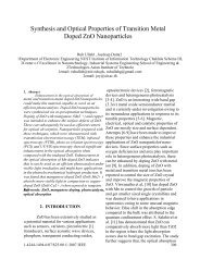
Option Evaluation by Weighted Sum Me<strong>th</strong>od<br />
Criteria Weight<br />
Option Rating (R)<br />
#1 Option #2 Option #3 Option #4 Option #5 Option<br />
R R*W R R*W R R*W R R*W R R*W<br />
Reduction in treatment/disposal costs 8 7 56 7 56 5 40 2 16 2 16<br />
Reduction <strong>of</strong> Input material costs 4 8 32 6 24 8 32 4 16 4 16<br />
Extent <strong>of</strong> current use in Industry 5 8 40 8 40 7 35 7 35 7 35<br />
Effect on Product quality (no effect=10) 10 9 90 9 90 2 20 8 80 8 80<br />
Low capital cost 5 2 10 5 25 4 20 7 35 8 40<br />
Low O and M cost 5 5 25 6 30 5 25 8 40 8 40<br />
Short Implementation period 8 3 24 5 40 3 24 7 56 8 64<br />
Ease <strong>of</strong> Implementation 7 3 21 6 42 5 35 7 49 8 56<br />
Reduction in Energy Bills 9 5 45 9 81 5 45 10 90 10 90<br />
Improvement in OHS 7 10 70 3 21 10 70 2 14 2 14<br />
Final<br />
Evaluation<br />
Sum <strong>of</strong> Weighted Ratings Σ (W*R) 413 449 346 431 451<br />
Option Ranking 4 2 5 3 1<br />
Feasibility Analysis Scheduled for (Date)
Audit Report<br />
Table <strong>of</strong> Contents<br />
Introduction..................................................................................................................................<br />
I. B<strong>ac</strong>kground ......................................................................................................................<br />
1.1 Objective .....................................................................................................................<br />
II. Planning and Organization 2<br />
2.1 Study Objectives..........................................................................................................<br />
2.2 Formation <strong>of</strong> <strong>th</strong>e Audit Team ....................................................................................<br />
2.3 Audit Appro<strong>ac</strong>h...........................................................................................................<br />
III. Assessment Preparation Phase ........................................................................................<br />
3.1 Plant's manuf<strong>ac</strong>turing process ...................................................................................<br />
3.1.1 Clo<strong>th</strong> dyeing section.....................................................................................<br />
3.1.2 Yarn dyeing section......................................................................................<br />
3.2 Material consumption and wastewater generation....................................................<br />
3.2.1 Raw material consumption..........................................................................<br />
3.2.2 Water usage..................................................................................................<br />
3.2.3 Wastewater char<strong>ac</strong>teristics ..........................................................................<br />
3.3 Performance <strong>of</strong> <strong>th</strong>e current effluent treatment plant .................................................<br />
3.3.1 Description...................................................................................................<br />
3.3.2 Assessment <strong>of</strong> <strong>th</strong>e effluent treatment plant.................................................<br />
IV. Assessment Phase - Proposed reduction options............................................................<br />
4.1 Obvious waste reduction measures............................................................................<br />
4.2 Long term waste reduction options ...........................................................................<br />
4.3 Major concerns <strong>of</strong> <strong>th</strong>e present effluent treatment plant ............................................<br />
V. Feasibility Analysis Phase: Techno-economical Evaluation ..........................................<br />
Conclusions ......................................................................................................................<br />
References<br />
Appendix A: Data Analysis<br />
B: Sequence <strong>of</strong> material handling observed during a one-batch period<br />
C: Detailed time schedule <strong>of</strong> <strong>th</strong>e audit team<br />
D: Water use values taken from literature<br />
E: Flow rate measurement device<br />
F: Segregated flow channel dimensions<br />
G: Wastewater treatment<br />
Visu/Kumar<br />
Total no. <strong>of</strong> pages: 30<br />
63