

Half-Bridge LLC Resonant Converter Design Using FSFR-Series ...
Half-Bridge LLC Resonant Converter Design Using FSFR-Series ...
Half-Bridge LLC Resonant Converter Design Using FSFR-Series ...

Create successful ePaper yourself
Turn your PDF publications into a flip-book with our unique Google optimized e-Paper software.
AN-4151 APPLICATION NOTE<br />
[STEP-6] <strong>Design</strong> the Transformer<br />
The worst case for the transformer design is the minimum<br />
switching frequency condition, which occurs at the<br />
minimum input voltage and full-load condition. To obtain<br />
the minimum switching frequency, plot the gain curve<br />
using gain Equation 9 and read the minimum switching<br />
frequency. The minimum number of turns for the<br />
transformer primary-side is obtained as:<br />
N<br />
min<br />
p<br />
nV ( V<br />
)<br />
<br />
2 f M B A<br />
o F<br />
min<br />
s V e<br />
(21)<br />
where Ae is the cross-sectional area of the transformer core<br />
in m 2 and B is the maximum flux density swing in Tesla,<br />
as shown in Figure 20. If there is no reference data, use<br />
B =0.3~0.4 T. Notice that a virtual gain MV is introduced,<br />
which is caused by the secondary-side leakage inductance<br />
(Refer to Figure 8).<br />
V RI<br />
B<br />
1/(2f s )<br />
n (V o +V F )/M V<br />
-n (V o +V F )/M V<br />
B<br />
Figure 20. Flux Density Swing<br />
Choose the proper number of turns for the secondary side<br />
that results in primary-side turns larger than Np min as:<br />
Np n Ns Np<br />
min<br />
(22)<br />
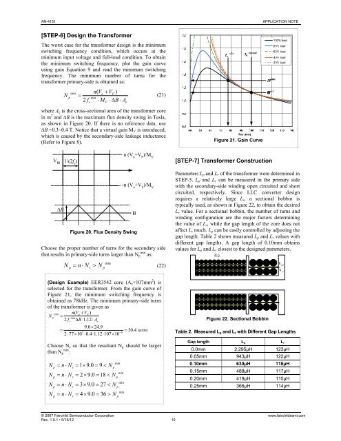
(<strong>Design</strong> Example) EER3542 core (Ae=107mm 2 ) is<br />
selected for the transformer. From the gain curve of<br />
Figure 21, the minimum switching frequency is<br />
obtained as 78kHz. The minimum primary-side turns<br />
of the transformer is given as<br />
min nV ( o VF)<br />
N p min<br />
2fs B1.12Ae 9.0 24.9<br />
30.4<br />
turns<br />
3 6<br />
277100.41.1210710 Choose Ns so that the resultant Np should be larger<br />
than Np min :<br />
N nN 19.09 N<br />
min<br />
p s p<br />
N nN 29.018 N<br />
min<br />
p s p<br />
N nN 39.027 N<br />
min<br />
p s p<br />
N nN 49.036 N<br />
min<br />
p s p<br />
Figure 21. Gain Curve<br />
[STEP-7] Transformer Construction<br />
Parameters Lp and Lr of the transformer were determined in<br />
STEP-5. Lp and Lr can be measured in the primary side<br />
with the secondary-side winding open circuited and short<br />
circuited, respectively. Since <strong>LLC</strong> converter design<br />
requires a relatively large Lr, a sectional bobbin is<br />
typically used, as shown in Figure 22, to obtain the desired<br />
Lr value. For a sectional bobbin, the number of turns and<br />
winding configuration are the major factors determining<br />
the value of Lr, while the gap length of the core does not<br />
affect Lr much. Lp can be easily controlled by adjusting the<br />
gap length. Table 2 shows measured Lp and Lr values with<br />
different gap lengths. A gap length of 0.10mm obtains<br />
values for Lp and Lr closest to the designed parameters.<br />
Np<br />
Figure 22. Sectional Bobbin<br />
Table 2. Measured Lp and Lr with Different Gap Lengths<br />
Gap length Lp Lr<br />
0.0mm 2,295μH 123μH<br />
0.05mm 943μH 122μH<br />
0.10mm 630μH 118μH<br />
0.15mm 488μH 117μH<br />
0.20mm 419μH 115μH<br />
0.25mm 366μH 114μH<br />
© 2007 Fairchild Semiconductor Corporation www.fairchildsemi.com<br />
Rev. 1.0.1 • 5/15/12 10<br />
N s2<br />
N s1


